EP1043459B1 - Dispositif de fixation d'une commande d'ouverture extérieure d'une porte de véhicule automobile - Google Patents
Dispositif de fixation d'une commande d'ouverture extérieure d'une porte de véhicule automobile Download PDFInfo
- Publication number
- EP1043459B1 EP1043459B1 EP00400739A EP00400739A EP1043459B1 EP 1043459 B1 EP1043459 B1 EP 1043459B1 EP 00400739 A EP00400739 A EP 00400739A EP 00400739 A EP00400739 A EP 00400739A EP 1043459 B1 EP1043459 B1 EP 1043459B1
- Authority
- EP
- European Patent Office
- Prior art keywords
- door
- edge
- casing
- cutout
- housing
- Prior art date
- Legal status (The legal status is an assumption and is not a legal conclusion. Google has not performed a legal analysis and makes no representation as to the accuracy of the status listed.)
- Expired - Lifetime
Links
Images


Classifications
-
- E—FIXED CONSTRUCTIONS
- E05—LOCKS; KEYS; WINDOW OR DOOR FITTINGS; SAFES
- E05B—LOCKS; ACCESSORIES THEREFOR; HANDCUFFS
- E05B79/00—Mounting or connecting vehicle locks or parts thereof
- E05B79/02—Mounting of vehicle locks or parts thereof
- E05B79/06—Mounting of handles, e.g. to the wing or to the lock
-
- E—FIXED CONSTRUCTIONS
- E05—LOCKS; KEYS; WINDOW OR DOOR FITTINGS; SAFES
- E05B—LOCKS; ACCESSORIES THEREFOR; HANDCUFFS
- E05B85/00—Details of vehicle locks not provided for in groups E05B77/00 - E05B83/00
- E05B85/10—Handles
- E05B85/14—Handles pivoted about an axis parallel to the wing
- E05B85/18—Handles pivoted about an axis parallel to the wing a longitudinal grip part being pivoted about an axis parallel to the longitudinal axis of the grip part
Definitions
- the present invention relates to a device for attaching an external door opening control of a motor vehicle.
- outdoor opening controls of a motor vehicle door are formed by an assembly comprising in particular a housing fixed on the door and on which is mounted a control member of the opening of said door.
- This control member is formed by a handle for example in the form of a palette.
- the case supporting the control member mounted on the panel external door is fixed by screwing on one or two tabs provided in a cut-out in the panel of door.
- an insert or screw pre-mounted on the housing of the door opening control is centered in a hole provided on the corresponding fixing lug and a nut locks the assembly in position on the panel of door.
- the object of the invention is to avoid these disadvantages by proposing a device for fixing an order external opening of a motor vehicle door which reduces the assembly time of the order opening on the door panel and also reduce costs through the reduction of the number of parts and in particular the removal of screws and nuts.
- the subject of the invention is therefore a device for attaching an external door opening control of a motor vehicle, of the type comprising an applied housing on the outer face of the edge of a cut-out in the door and supporting an opening control member of said door, said housing being held by pinching at least a portion of the edge of the blank between said housing and a piece applied on the inner side of the edge of this cut, characterized in that the piece is formed by a stirrup having at least one finger extending in parallel to the longitudinal direction of the door and intended to enter a bridge provided on the back side of the housing.
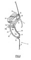
- FIG. 1 schematically shown a door 1 of a motor vehicle which comprises, in front, that is to say on the outer face of the panel 2, a cutout 3 intended to receive an order to open the door 1 held on said blank 3 by means of a device fixing device according to the invention.
- the opening command of the door 1 comprises in particular a housing 10 to be applied on the outer face of the edge 3a of the cutout 3 formed in the panel 2 of the door 1.
- the housing 10 supports a control member of the opening of the door 1 which, in the example shown in FIG. 2, consists of a pallet 11.
- the housing 10 has on its face internal 10a two legs 12 parallel and extending towards the high.
- Each leg 12 is provided at its upper part of a transverse orifice 12a for the passage of an axis, as we will see later.
- the pallet 11 has on its rear face two arms 13 parallel and also extending upwards.
- Each arm 13 is provided at its upper part of an orifice 13a for the passage of an axis and passes through the housing 10 through an opening 14 formed in said housing 10.
- the pallet 11 is mounted on the housing 10 in introducing each arm 13 into an opening 14 so to position the upper end of each arm 13 in look at the upper end of a leg 12.
- an axis is introduced in the orifice 12a of a tab 12 and in the orifice 13a of a arm 13 adjacent such that the pallet 11 pivots around these axes and control, during this pivoting, the opening of the door via a suitable mechanism and connected to said pallet 11.
- the housing 10 also has on its rear face 10a two bridges, respectively 15a and 15b, parallel and each provided with an axial passage, respectively 16a and 16b, extending parallel to the longitudinal direction from the door 1.
- the outer contour housing 10 supporting the pallet 11 is placed on the outer face of the edge 3a of the cutout 3 and is maintained by pinching this edge 3a between the housing 10 and a part 20 applied on the inner face of the edge 3a of this cutout 3.
- the part 20 is formed by a stirrup 21 of length less than the length of the housing 10 and whose outer contour covers only part of the face internal edge 3a of the cutout 3.
- the stirrup 21 has two fingers 22a respectively and 22b, extending parallel to the longitudinal direction of Door 1 and intended to penetrate each into the passage 16a or 16b of a bridge 15a or 15b formed on the face rear 10a of the housing 10.
- the finger 22a is arranged opposite a notch 23 provided on the stirrup 21 and the finger 22b is arranged on the end 21a of the stirrup 21.
- the width of the fingers 22a and 22b is smaller to the width of the passages 16a and 16b of the bridges 15a and 15b so as to allow transverse movement of the stirrup 21 when mounting this bracket 21 on the housing 10.
- stirrup 21 and housing 10 are determined so that the fingers 22a and 22b and the bridges 15a and 15b exert, on the one hand, a force pressing the housing 10 on the outer face of the edge 3a of the cutting 3 and, on the other hand, by reaction, an opposite force placing the stirrup 21 on the inner face of the edge 3a of said cutting 3.
- the mounting of the stirrup 21 on the housing 10 is realized in the following way.
- the housing 10 supporting the pallet 11 is placed on the outer face of the edge 3a of the blank 3 and the stirrup 21 is moved in a longitudinal direction of the door 1 so that the fingers 22a and 22b penetrate in the passages 16a and 16b of the bridges 15a and 15b.
- stirrup 21 is crushed slightly against the inner face of the panel 2 of the door 1 of such way that the fingers 22a and 22b are positioned in the axis of the passages 16a and 16b of the bridges 15a and 15b.
- the fingers 22a and 22b move backwards compared to the outer face of the door 1, so that the rim of the stirrup 21 rests on the inner face of the edge 3a of the cutout 3, and pull the housing 10 also backward by plating it on the edge 3a of said cutout 3.
- edge 3a of the cutout 3 is pinched between the housing 10 and the stirrup 21, which ensures the fixation housing 10 and the control member of the opening of the door 1 of the motor vehicle.
- the fixing device comprises locking means preventing inadvertent disassembly of the stirrup 21.
- these locking means are formed by a resilient tongue 25 cooperating with a stop 26 provided on the housing 10 ( Figure 3).
- the fastening device according to the invention allows to reduce the assembly time of an opening command outside door on the panel of this door and not requires no screwing device, which also makes it possible to reduce costs due to the removal of screws and nuts.
- the fastening device according to the invention allows also the mounting of the external opening control in hard-to-reach areas for tools screwing.
Description
- la forme et les dimensions de l'étrier et du boítier sont déterminées pour que ledit doigt et ledit pontet exercent, d'une part, une force plaquant le boítier sur la face externe du bord de la découpe et, d'autre part, par réaction, une force opposée plaquant l'étrier sur la face interne du bord de ladite découpe,
- le montage de l'étrier sur le boítier s'effectue par déplacement de l'étrier selon une direction longitudinale de la porte,
- le dispositif comporte des moyens de blocage empêchant un démontage intempestif de l'étrier,
- les moyens de blocage sont formés par une languette élastique coopérant avec une butée prévue sur la porte.
- la Fig. 1 est une vue schématique en élévation d'une porte d'un véhicule automobile destinée à recevoir une commande d'ouverture fixée par un dispositif conforme à l'invention,
- la Fig. 2 est une vue schématique en coupe transversale de la commande d'ouverture fixée par le dispositif conforme à l'invention,
- la Fig. 3 est une vue schématique en perspective du boítier de la commande d'ouverture,
- la Fig. 4 est une vue schématique en perspective de l'étrier du dispositif de fixation de la commande d'ouverture.
Claims (5)
- Dispositif de fixation d'une commande d'ouverture extérieure d'une porte (1) de véhicule automobile, du type comprenant un boítier (10) appliqué sur la face externe du bord (3a) d'une découpe (3) ménagée sur la porte (1) et supportant un organe (11) de commande de l'ouverture de ladite porte (1), ledit boítier (10) étant maintenu par pincement d'au moins une portion du bord (3a) de la découpe (3) entre ledit boítier (10) et une pièce (20) appliquée sur la face interne du bord (3a) de la découpe (3), caractérisé en ce que la pièce (20) est formée par un étrier (21) comportant au moins un doigt (22a, 22b) s'étendant parallèlement à la direction longitudinale de la porte (1) et destiné à pénétrer dans un pontet (15a, 15b) prévu sur la face arrière du boítier (10).
- Dispositif selon la revendication 1, caractérisé en ce que la forme et les dimensions de l'étrier (21) et du boítier (10) sont déterminées pour que ledit doigt (22a, 22b) et ledit pontet (15a, 15b) exercent, d'une part, une force plaquant le boítier (10) sur la face externe du bord (3a) de la découpe (3) et, d'autre part, par réaction, une force opposée plaquant l'étrier (21) sur la face interne au bord (3a) de ladite découpe (3).
- Dispositif selon la revendication 1 ou 2, caractérisé en ce que le montage de l'étrier (21) sur le boítier (10) s'effectue par déplacement de l'étrier (21) selon une direction longitudinale de la porte (1).
- Dispositif selon la revendication 1, caractérisé en ce qu'il comporte des moyens (25, 26) de blocage empêchant un démontage intempestif de l'étrier (21).
- Dispositif selon la revendication 4, caractérisé en ce que les moyens de blocage sont formés par une languette élastique (25) coopérant avec une butée (26) prévue sur la porte (1).
Applications Claiming Priority (2)
| Application Number | Priority Date | Filing Date | Title |
|---|---|---|---|
| FR9904481A FR2791926B1 (fr) | 1999-04-09 | 1999-04-09 | Dispositif de fixation d'une commande d'ouverture exterieure d'une porte de vehicule automobile |
| FR9904481 | 1999-04-09 |
Publications (2)
| Publication Number | Publication Date |
|---|---|
| EP1043459A1 EP1043459A1 (fr) | 2000-10-11 |
| EP1043459B1 true EP1043459B1 (fr) | 2005-02-23 |
Family
ID=9544242
Family Applications (1)
| Application Number | Title | Priority Date | Filing Date |
|---|---|---|---|
| EP00400739A Expired - Lifetime EP1043459B1 (fr) | 1999-04-09 | 2000-03-16 | Dispositif de fixation d'une commande d'ouverture extérieure d'une porte de véhicule automobile |
Country Status (5)
| Country | Link |
|---|---|
| EP (1) | EP1043459B1 (fr) |
| AT (1) | ATE289650T1 (fr) |
| DE (1) | DE60018229T2 (fr) |
| ES (1) | ES2237394T3 (fr) |
| FR (1) | FR2791926B1 (fr) |
Family Cites Families (6)
| Publication number | Priority date | Publication date | Assignee | Title |
|---|---|---|---|---|
| DE2824216A1 (de) * | 1978-06-02 | 1979-12-06 | Volkswagenwerk Ag | Betaetigungsvorrichtung fuer einen tuerverschluss, insbesondere innenbetaetigungsvorrichtung fuer einen kraftfahrzeug-tuerverschluss |
| JPH0723656B2 (ja) * | 1987-10-21 | 1995-03-15 | 三井金属鉱業株式会社 | 車両用扉へのアウターハンドル取付装置 |
| FR2677395B1 (fr) * | 1991-06-07 | 1995-10-13 | Peugeot | Poignee de porte pivotante. |
| US5101597A (en) * | 1991-08-06 | 1992-04-07 | General Motors Corporation | Door handle bracket attachment for vehicle door |
| DE4443117B4 (de) * | 1994-12-02 | 2005-03-03 | Ewald Witte Gmbh & Co Kg | In eine Öffnung einer Tür, insbesondere Kraftfahrzeug-Tür einsetzbarer Griffbeschlag |
| FR2729697A1 (fr) * | 1995-01-25 | 1996-07-26 | Valeo Securite Habitacle | Poignee de porte de vehicule automobile a montage rapide par systeme coin-came |
-
1999
- 1999-04-09 FR FR9904481A patent/FR2791926B1/fr not_active Expired - Fee Related
-
2000
- 2000-03-16 DE DE60018229T patent/DE60018229T2/de not_active Expired - Lifetime
- 2000-03-16 EP EP00400739A patent/EP1043459B1/fr not_active Expired - Lifetime
- 2000-03-16 AT AT00400739T patent/ATE289650T1/de not_active IP Right Cessation
- 2000-03-16 ES ES00400739T patent/ES2237394T3/es not_active Expired - Lifetime
Also Published As
| Publication number | Publication date |
|---|---|
| DE60018229D1 (de) | 2005-03-31 |
| ES2237394T3 (es) | 2005-08-01 |
| EP1043459A1 (fr) | 2000-10-11 |
| FR2791926B1 (fr) | 2001-06-29 |
| FR2791926A1 (fr) | 2000-10-13 |
| ATE289650T1 (de) | 2005-03-15 |
| DE60018229T2 (de) | 2005-12-29 |
Similar Documents
| Publication | Publication Date | Title |
|---|---|---|
| EP0194200B1 (fr) | Collier de serrage télémanipulable | |
| EP1241072B1 (fr) | Assemblage d'un étrier de colonne de direction avec un pignon de direction d'un véhicule automobile | |
| WO2000071376A1 (fr) | Dispositif de fixation d'un radiateur sur un support d'un vehicule | |
| FR2770880A1 (fr) | Ensemble pour le positionnement, le centrage et le maintien en service d'une piece mecanique | |
| EP2516243A1 (fr) | Dispositif pour fixer une plaquette contre une plane d ' une piece fixe d ' un vehicule automobile | |
| EP0023440A1 (fr) | Dispositif d'immobilisation d'écrous prisonniers | |
| EP0309344A1 (fr) | Dispositif d'accouplement pour une colonne de direction et véhicule équipé d'un tel dispositif | |
| EP1043459B1 (fr) | Dispositif de fixation d'une commande d'ouverture extérieure d'une porte de véhicule automobile | |
| EP0706929B1 (fr) | Dispositif de fixation d'un moyeu de volant de direction de véhicule automobile sur un arbre de direction | |
| FR2764010A1 (fr) | Dispositif en materiau thermoplastique elastique destine au montage d'une platine support d'un accessoire sur une plaque | |
| EP2017408B1 (fr) | Dispositif de prépositionnement d'une gâche destinée à coopérer avec une serrure d'un ouvrant de véhicule automobile et véhicule automobile comportant au moins un tel dispositif | |
| EP0209444B1 (fr) | Ensemble de serrure de porte, notamment pour véhicule automobile | |
| EP0326481A1 (fr) | Ecrou en forme de pince et assemblage réalisé à l'aide de cet écrou | |
| FR2733285A1 (fr) | Dispositif de fixation mecanique rigide destine a une rotule, ensemble le comprenant et procedes de montage et demontage | |
| FR2768197A1 (fr) | Fixation auto-liberante au serrage, notamment pour une aile plastique d'un vehicule automobile | |
| EP1258389B1 (fr) | Dispositif d'obturation d'un orifice traversant une paroi et destiné à la fixation d'un objet, tel qu'un siège de véhicule automobile | |
| EP1104736B1 (fr) | Dispositif d'assemblage d'un pignon de direction avec un étrier | |
| EP2022921B1 (fr) | Dispositif de fixation d'une pièce à un support, tel qu'une vitre, du type à ècrou et vis | |
| FR2705746A1 (fr) | Dispositif de fixation d'un élément, tel qu'accoudoir ou crosse de porte de véhicule automobile, à une structure fixe. | |
| FR2658878A1 (fr) | Dispositif de connexion rapide entre deux portions d'une timonerie, notamment pour vehicule automobile. | |
| EP1300535B1 (fr) | Butée réglable pour éléments mobiles de carrosserie de véhicule automobile | |
| EP1672226B1 (fr) | Dispositif de fixation d'une pièce sur un moteur de véhicule automobile et utilisation du dispositif pour la fixation d`un catalyseur | |
| EP1213489A1 (fr) | Fixation d'une pièce par rapport à une autre, avec positionnement dans les trois axes, notamment pour pièce d'habillage de véhicule automobile | |
| FR2760799A1 (fr) | Dispositif de fixation amovible destine notamment a un element de carrosserie | |
| EP0860324A1 (fr) | Dispositif de fixation d'un rétroviseur extérieur sur un véhicule automobile |
Legal Events
| Date | Code | Title | Description |
|---|---|---|---|
| PUAI | Public reference made under article 153(3) epc to a published international application that has entered the european phase |
Free format text: ORIGINAL CODE: 0009012 |
|
| AK | Designated contracting states |
Kind code of ref document: A1 Designated state(s): AT BE CH CY DE DK ES FI FR GB GR IE IT LI LU MC NL PT SE |
|
| AX | Request for extension of the european patent |
Free format text: AL;LT;LV;MK;RO;SI |
|
| 17P | Request for examination filed |
Effective date: 20010324 |
|
| AKX | Designation fees paid |
Free format text: AT BE CH CY DE DK ES FI FR GB GR IE IT LI LU MC NL PT SE |
|
| 17Q | First examination report despatched |
Effective date: 20030811 |
|
| GRAP | Despatch of communication of intention to grant a patent |
Free format text: ORIGINAL CODE: EPIDOSNIGR1 |
|
| GRAS | Grant fee paid |
Free format text: ORIGINAL CODE: EPIDOSNIGR3 |
|
| GRAA | (expected) grant |
Free format text: ORIGINAL CODE: 0009210 |
|
| AK | Designated contracting states |
Kind code of ref document: B1 Designated state(s): AT BE CH CY DE DK ES FI FR GB GR IE IT LI LU MC NL PT SE |
|
| PG25 | Lapsed in a contracting state [announced via postgrant information from national office to epo] |
Ref country code: AT Free format text: LAPSE BECAUSE OF FAILURE TO SUBMIT A TRANSLATION OF THE DESCRIPTION OR TO PAY THE FEE WITHIN THE PRESCRIBED TIME-LIMIT Effective date: 20050223 Ref country code: IE Free format text: LAPSE BECAUSE OF FAILURE TO SUBMIT A TRANSLATION OF THE DESCRIPTION OR TO PAY THE FEE WITHIN THE PRESCRIBED TIME-LIMIT Effective date: 20050223 Ref country code: NL Free format text: LAPSE BECAUSE OF FAILURE TO SUBMIT A TRANSLATION OF THE DESCRIPTION OR TO PAY THE FEE WITHIN THE PRESCRIBED TIME-LIMIT Effective date: 20050223 Ref country code: FI Free format text: LAPSE BECAUSE OF FAILURE TO SUBMIT A TRANSLATION OF THE DESCRIPTION OR TO PAY THE FEE WITHIN THE PRESCRIBED TIME-LIMIT Effective date: 20050223 |
|
| REG | Reference to a national code |
Ref country code: GB Ref legal event code: FG4D Free format text: NOT ENGLISH |
|
| REG | Reference to a national code |
Ref country code: CH Ref legal event code: EP |
|
| PG25 | Lapsed in a contracting state [announced via postgrant information from national office to epo] |
Ref country code: CY Free format text: LAPSE BECAUSE OF FAILURE TO SUBMIT A TRANSLATION OF THE DESCRIPTION OR TO PAY THE FEE WITHIN THE PRESCRIBED TIME-LIMIT Effective date: 20050316 Ref country code: LU Free format text: LAPSE BECAUSE OF NON-PAYMENT OF DUE FEES Effective date: 20050316 |
|
| REG | Reference to a national code |
Ref country code: IE Ref legal event code: FG4D Free format text: FRENCH |
|
| PG25 | Lapsed in a contracting state [announced via postgrant information from national office to epo] |
Ref country code: LI Free format text: LAPSE BECAUSE OF NON-PAYMENT OF DUE FEES Effective date: 20050331 Ref country code: MC Free format text: LAPSE BECAUSE OF NON-PAYMENT OF DUE FEES Effective date: 20050331 Ref country code: BE Free format text: LAPSE BECAUSE OF NON-PAYMENT OF DUE FEES Effective date: 20050331 Ref country code: CH Free format text: LAPSE BECAUSE OF NON-PAYMENT OF DUE FEES Effective date: 20050331 |
|
| REF | Corresponds to: |
Ref document number: 60018229 Country of ref document: DE Date of ref document: 20050331 Kind code of ref document: P |
|
| PG25 | Lapsed in a contracting state [announced via postgrant information from national office to epo] |
Ref country code: DK Free format text: LAPSE BECAUSE OF FAILURE TO SUBMIT A TRANSLATION OF THE DESCRIPTION OR TO PAY THE FEE WITHIN THE PRESCRIBED TIME-LIMIT Effective date: 20050523 Ref country code: SE Free format text: LAPSE BECAUSE OF FAILURE TO SUBMIT A TRANSLATION OF THE DESCRIPTION OR TO PAY THE FEE WITHIN THE PRESCRIBED TIME-LIMIT Effective date: 20050523 Ref country code: GR Free format text: LAPSE BECAUSE OF FAILURE TO SUBMIT A TRANSLATION OF THE DESCRIPTION OR TO PAY THE FEE WITHIN THE PRESCRIBED TIME-LIMIT Effective date: 20050523 |
|
| GBT | Gb: translation of ep patent filed (gb section 77(6)(a)/1977) |
Effective date: 20050512 |
|
| NLV1 | Nl: lapsed or annulled due to failure to fulfill the requirements of art. 29p and 29m of the patents act | ||
| REG | Reference to a national code |
Ref country code: ES Ref legal event code: FG2A Ref document number: 2237394 Country of ref document: ES Kind code of ref document: T3 |
|
| PG25 | Lapsed in a contracting state [announced via postgrant information from national office to epo] |
Ref country code: PT Free format text: LAPSE BECAUSE OF FAILURE TO SUBMIT A TRANSLATION OF THE DESCRIPTION OR TO PAY THE FEE WITHIN THE PRESCRIBED TIME-LIMIT Effective date: 20050803 |
|
| REG | Reference to a national code |
Ref country code: IE Ref legal event code: FD4D |
|
| BERE | Be: lapsed |
Owner name: PEUGEOT CITROEN AUTOMOBILES SA Effective date: 20050331 |
|
| REG | Reference to a national code |
Ref country code: CH Ref legal event code: PL |
|
| PLBE | No opposition filed within time limit |
Free format text: ORIGINAL CODE: 0009261 |
|
| STAA | Information on the status of an ep patent application or granted ep patent |
Free format text: STATUS: NO OPPOSITION FILED WITHIN TIME LIMIT |
|
| PG25 | Lapsed in a contracting state [announced via postgrant information from national office to epo] |
Ref country code: FR Free format text: LAPSE BECAUSE OF NON-PAYMENT OF DUE FEES Effective date: 20060131 |
|
| 26N | No opposition filed |
Effective date: 20051124 |
|
| REG | Reference to a national code |
Ref country code: FR Ref legal event code: ST Effective date: 20060131 |
|
| REG | Reference to a national code |
Ref country code: GB Ref legal event code: 746 Effective date: 20070118 |
|
| BERE | Be: lapsed |
Owner name: PEUGEOT CITROEN AUTOMOBILES SA Effective date: 20050331 |
|
| PGFP | Annual fee paid to national office [announced via postgrant information from national office to epo] |
Ref country code: ES Payment date: 20080307 Year of fee payment: 9 |
|
| PGFP | Annual fee paid to national office [announced via postgrant information from national office to epo] |
Ref country code: IT Payment date: 20080307 Year of fee payment: 9 |
|
| PG25 | Lapsed in a contracting state [announced via postgrant information from national office to epo] |
Ref country code: FR Free format text: LAPSE BECAUSE OF NON-PAYMENT OF DUE FEES Effective date: 20050331 |
|
| REG | Reference to a national code |
Ref country code: ES Ref legal event code: FD2A Effective date: 20090317 |
|
| PG25 | Lapsed in a contracting state [announced via postgrant information from national office to epo] |
Ref country code: ES Free format text: LAPSE BECAUSE OF NON-PAYMENT OF DUE FEES Effective date: 20090317 |
|
| PG25 | Lapsed in a contracting state [announced via postgrant information from national office to epo] |
Ref country code: IT Free format text: LAPSE BECAUSE OF NON-PAYMENT OF DUE FEES Effective date: 20090316 |
|
| PGFP | Annual fee paid to national office [announced via postgrant information from national office to epo] |
Ref country code: DE Payment date: 20150219 Year of fee payment: 16 |
|
| PGFP | Annual fee paid to national office [announced via postgrant information from national office to epo] |
Ref country code: GB Payment date: 20150226 Year of fee payment: 16 |
|
| REG | Reference to a national code |
Ref country code: DE Ref legal event code: R119 Ref document number: 60018229 Country of ref document: DE |
|
| GBPC | Gb: european patent ceased through non-payment of renewal fee |
Effective date: 20160316 |
|
| PG25 | Lapsed in a contracting state [announced via postgrant information from national office to epo] |
Ref country code: GB Free format text: LAPSE BECAUSE OF NON-PAYMENT OF DUE FEES Effective date: 20160316 Ref country code: DE Free format text: LAPSE BECAUSE OF NON-PAYMENT OF DUE FEES Effective date: 20161001 |