EP1241072B1 - Connection of a steering column clamp with a motor vehicle steering pinion - Google Patents
Connection of a steering column clamp with a motor vehicle steering pinion Download PDFInfo
- Publication number
- EP1241072B1 EP1241072B1 EP02290290A EP02290290A EP1241072B1 EP 1241072 B1 EP1241072 B1 EP 1241072B1 EP 02290290 A EP02290290 A EP 02290290A EP 02290290 A EP02290290 A EP 02290290A EP 1241072 B1 EP1241072 B1 EP 1241072B1
- Authority
- EP
- European Patent Office
- Prior art keywords
- antirotation
- clamping
- bearing
- bracket
- nut
- Prior art date
- Legal status (The legal status is an assumption and is not a legal conclusion. Google has not performed a legal analysis and makes no representation as to the accuracy of the status listed.)
- Expired - Lifetime
Links
- 210000002105 tongue Anatomy 0.000 claims description 11
- 238000006386 neutralization reaction Methods 0.000 claims description 4
- 230000003100 immobilizing effect Effects 0.000 claims 3
- 238000003780 insertion Methods 0.000 claims 1
- 230000037431 insertion Effects 0.000 claims 1
- 208000031968 Cadaver Diseases 0.000 description 5
- 230000000903 blocking effect Effects 0.000 description 2
- 238000012423 maintenance Methods 0.000 description 2
- 238000012550 audit Methods 0.000 description 1
Images


Classifications
-
- F—MECHANICAL ENGINEERING; LIGHTING; HEATING; WEAPONS; BLASTING
- F16—ENGINEERING ELEMENTS AND UNITS; GENERAL MEASURES FOR PRODUCING AND MAINTAINING EFFECTIVE FUNCTIONING OF MACHINES OR INSTALLATIONS; THERMAL INSULATION IN GENERAL
- F16B—DEVICES FOR FASTENING OR SECURING CONSTRUCTIONAL ELEMENTS OR MACHINE PARTS TOGETHER, e.g. NAILS, BOLTS, CIRCLIPS, CLAMPS, CLIPS OR WEDGES; JOINTS OR JOINTING
- F16B37/00—Nuts or like thread-engaging members
- F16B37/04—Devices for fastening nuts to surfaces, e.g. sheets, plates
- F16B37/044—Nut cages
-
- B—PERFORMING OPERATIONS; TRANSPORTING
- B62—LAND VEHICLES FOR TRAVELLING OTHERWISE THAN ON RAILS
- B62D—MOTOR VEHICLES; TRAILERS
- B62D1/00—Steering controls, i.e. means for initiating a change of direction of the vehicle
- B62D1/02—Steering controls, i.e. means for initiating a change of direction of the vehicle vehicle-mounted
- B62D1/16—Steering columns
- B62D1/20—Connecting steering column to steering gear
-
- F—MECHANICAL ENGINEERING; LIGHTING; HEATING; WEAPONS; BLASTING
- F16—ENGINEERING ELEMENTS AND UNITS; GENERAL MEASURES FOR PRODUCING AND MAINTAINING EFFECTIVE FUNCTIONING OF MACHINES OR INSTALLATIONS; THERMAL INSULATION IN GENERAL
- F16B—DEVICES FOR FASTENING OR SECURING CONSTRUCTIONAL ELEMENTS OR MACHINE PARTS TOGETHER, e.g. NAILS, BOLTS, CIRCLIPS, CLAMPS, CLIPS OR WEDGES; JOINTS OR JOINTING
- F16B2/00—Friction-grip releasable fastenings
- F16B2/02—Clamps, i.e. with gripping action effected by positive means other than the inherent resistance to deformation of the material of the fastening
- F16B2/18—Clamps, i.e. with gripping action effected by positive means other than the inherent resistance to deformation of the material of the fastening using cams, levers, eccentrics, or toggles
-
- F—MECHANICAL ENGINEERING; LIGHTING; HEATING; WEAPONS; BLASTING
- F16—ENGINEERING ELEMENTS AND UNITS; GENERAL MEASURES FOR PRODUCING AND MAINTAINING EFFECTIVE FUNCTIONING OF MACHINES OR INSTALLATIONS; THERMAL INSULATION IN GENERAL
- F16D—COUPLINGS FOR TRANSMITTING ROTATION; CLUTCHES; BRAKES
- F16D1/00—Couplings for rigidly connecting two coaxial shafts or other movable machine elements
- F16D1/06—Couplings for rigidly connecting two coaxial shafts or other movable machine elements for attachment of a member on a shaft or on a shaft-end
- F16D1/08—Couplings for rigidly connecting two coaxial shafts or other movable machine elements for attachment of a member on a shaft or on a shaft-end with clamping hub; with hub and longitudinal key
- F16D1/0852—Couplings for rigidly connecting two coaxial shafts or other movable machine elements for attachment of a member on a shaft or on a shaft-end with clamping hub; with hub and longitudinal key with radial clamping between the mating surfaces of the hub and shaft
- F16D1/0864—Couplings for rigidly connecting two coaxial shafts or other movable machine elements for attachment of a member on a shaft or on a shaft-end with clamping hub; with hub and longitudinal key with radial clamping between the mating surfaces of the hub and shaft due to tangential loading of the hub, e.g. a split hub
-
- F—MECHANICAL ENGINEERING; LIGHTING; HEATING; WEAPONS; BLASTING
- F16—ENGINEERING ELEMENTS AND UNITS; GENERAL MEASURES FOR PRODUCING AND MAINTAINING EFFECTIVE FUNCTIONING OF MACHINES OR INSTALLATIONS; THERMAL INSULATION IN GENERAL
- F16D—COUPLINGS FOR TRANSMITTING ROTATION; CLUTCHES; BRAKES
- F16D3/00—Yielding couplings, i.e. with means permitting movement between the connected parts during the drive
- F16D3/16—Universal joints in which flexibility is produced by means of pivots or sliding or rolling connecting parts
- F16D3/26—Hooke's joints or other joints with an equivalent intermediate member to which each coupling part is pivotally or slidably connected
- F16D3/38—Hooke's joints or other joints with an equivalent intermediate member to which each coupling part is pivotally or slidably connected with a single intermediate member with trunnions or bearings arranged on two axes perpendicular to one another
- F16D3/382—Hooke's joints or other joints with an equivalent intermediate member to which each coupling part is pivotally or slidably connected with a single intermediate member with trunnions or bearings arranged on two axes perpendicular to one another constructional details of other than the intermediate member
- F16D3/387—Fork construction; Mounting of fork on shaft; Adapting shaft for mounting of fork
-
- F—MECHANICAL ENGINEERING; LIGHTING; HEATING; WEAPONS; BLASTING
- F16—ENGINEERING ELEMENTS AND UNITS; GENERAL MEASURES FOR PRODUCING AND MAINTAINING EFFECTIVE FUNCTIONING OF MACHINES OR INSTALLATIONS; THERMAL INSULATION IN GENERAL
- F16B—DEVICES FOR FASTENING OR SECURING CONSTRUCTIONAL ELEMENTS OR MACHINE PARTS TOGETHER, e.g. NAILS, BOLTS, CIRCLIPS, CLAMPS, CLIPS OR WEDGES; JOINTS OR JOINTING
- F16B2200/00—Constructional details of connections not covered for in other groups of this subclass
- F16B2200/69—Redundant disconnection blocking means
-
- Y—GENERAL TAGGING OF NEW TECHNOLOGICAL DEVELOPMENTS; GENERAL TAGGING OF CROSS-SECTIONAL TECHNOLOGIES SPANNING OVER SEVERAL SECTIONS OF THE IPC; TECHNICAL SUBJECTS COVERED BY FORMER USPC CROSS-REFERENCE ART COLLECTIONS [XRACs] AND DIGESTS
- Y10—TECHNICAL SUBJECTS COVERED BY FORMER USPC
- Y10T—TECHNICAL SUBJECTS COVERED BY FORMER US CLASSIFICATION
- Y10T403/00—Joints and connections
- Y10T403/70—Interfitted members
- Y10T403/7075—Interfitted members including discrete retainer
Definitions
- the present invention relates to the device assembling a stirrup with a shaft, and the invention relates more particularly to assembly device of a column stirrup steering with a steering gear of a vehicle automobile, which constitutes the connection of the steering column with the steering box.
- the bolt makes it possible to tighten the two branches of the caliper against the pinion shaft, in relying on each of the external faces of branches of said stirrup.
- These types of devices assembly require an environment in the vehicle that allows easy access during assembly and tightening; and moreover it is necessary to provide specific tools that allow the correct presentation of the nut during assembly and the engagement of the screw, and that ensures the maintenance in rotation of the nut during tightening.
- these types of fasteners do not guarantee by maintaining clamping when using the vehicle.
- the purpose of the present invention is to propose a device for assembling a column stirrup direction with a pinion steering, which avoids disadvantages described above, and which allows a particularly easy assembly blind in a reduced size and without specific tools, while guaranteeing the permanence of the assembly.
- the Axial prepositioning thrust is built into the anti-rotation elastic support element.
- the stop axial prepositioning is integrated into the stirrup.
- the axial stop of prepositioning is integrated into one of the branches of the attachment portion of the elastic element antirotation support.
- the internal cylindrical end eccentric of the clamping nut is provided with a face inclined relative to the clamping axis, in order to allow the engagement of the tree following a direction parallel to the caliper amounts.
- the internal cylindrical end of the nut is eccentric to the body cylindrical, so that said end inner cylindrical and said cylindrical body a common generator, which is arranged on the side opposite to the shaft with respect to the clamping axis, when the clamping and locking assembly is in unlocked position.
- a particularly interesting application of the invention relates to a steering column of a motor vehicle, in which the caliper is mounted on said steering column and the shaft belongs to the gearbox gearbox.
- the assembly device of a caliper steering column with a steering gear of a motor vehicle thus presents the advantage of allowing an assembly with the nut of clamping, which is held in position; which avoids any risk of loss and allows assembly in blind in a small footprint.
- locked position with nut lock against the shaft guarantees the maintenance in position of the stirrup on the shaft with the required tightening.
- the device of the invention relates to a assembly of a stirrup 1 with a shaft 2 like that is shown in Figures 2 and 15.
- a particularly interesting application of the invention relates to a steering column of a motor vehicle in which caliper 1 is mounted on said steering column, and the shaft 2 belongs to the gearbox gearbox.
- the connecting device which connects the stirrup 1 of the steering column to the shaft 2 of the steering gear, includes a clamping assembly and locking said shaft 2 in the stirrup 1.
- This clamping and blocking assembly is basically constituted by a clamping screw 3, which cooperates with a clamping nut 4 along a clamping axis 6.
- the entire steering column which is not shown in the figures, door at its end lower a universal joint 8 of the type "cardan".
- the universal joint 8 is integral on the one hand with the steering column, and secondly of the caliper 1.
- the steering pinion has an axis 5, which is the axis of the shaft 2.
- the axis 5 is therefore the axis assembly of the stirrup 1 on the shaft 2.
- the stirrup 1 has a cross-section through compared to axis 5, which is U-shaped.
- the stirrup 1 consists of two branches 11 and 12, which are substantially parallel to each other.
- the branches 11 and 12 are connected to each other by a connecting portion 21 which has substantially a circular half-crown section.
- Branches 11 and 12 and the connecting portion 21 constitute the housing 22 of the stirrup 1.
- the portion of connection 21 has an outer face 24 and a face 23, which constitutes the bottom of the housing 22 of the stirrup 1.
- the inner face 23 has a curvature substantially semicircular and of similar size of the circular section of the tree 2.
- Branch 11 has an outer face 17 and a face internal 19, while the branch 12 has a face 18 and an inner face 20.
- a housing 13 is arranged on the outer face 17, and a housing 14 is arranged on the outer face 18.
- Branch 11 is provided with a hole 15, which allows the passage of the screw 3, and the branch 12 has a hole 16 which constitutes the housing and the support of the nut of 4. Holes 15 and 16 are aligned next the clamping axis 6, which is substantially perpendicular to branches 11 and 12, and more precisely to the external faces 17 and 18 and to the faces internal 19 and 20.
- the tree 2 has a circular section with one face cylindrical 25 (see Figure 2).
- a first flat 27 and a second flat 28 are arranged on the shaft 2, and they are substantially parallel one by report to the other.
- the thickness of the shaft 2 between two flats 27 and 28 is substantially adjacent and slightly less than the distance between the two internal faces 19 and 20 of the branches 11 and 12.
- a third flat 26 is arranged on the shaft 2 so that this third flat 26 is substantially perpendicular to the first flat 27 and at the second flat 28.
- the clamping screw 3 has a body 33 with, at one from its ends, a head 31 provided with a collar 32.
- the body 33 is equipped a threaded portion 34 with a tip 35 provided with a transverse face 36.
- the hole 15, which is arranged in the branch 11, is sized to allow free passage the threaded portion 34 of the clamping screw 3, the collar 32 is applied against the face external 17 of the branch 11.
- the tightening nut 4 has a body cylindrical 41 which mounts in the hole 16 of the branch 12 of the stirrup 1.
- the hole 16 is sized so that the cylindrical body 41 fits correctly in said hole 16 of branch 12 which supports the tightening nut 4.
- the cylindrical body 41 is extended by an internal cylindrical end 43 which enters the housing 22 of the stirrup 1.
- the cylindrical body 41 is extended to the outside of branch 12 by a collar 42, which is applied against the outer face 18 of said branch 12.
- the clamping nut 4 is arranged in one of the two branches 12 of the stirrup 1; and the screw 3 crosses the other branch 11 of the stirrup 1.
- the tightening nut 4 is held in place in rotation and translation along the axis of tightening 6, when the clamping and locking assembly is in unlocked position. As shown on FIG. 9, holding in place in rotation and in translation is provided by an elastic element support antirotation 7 of the tightening nut 4.
- the tightening nut 4 is provided with a protrusion radial 9 which is disposed at its outer periphery.
- an axial prepositioning stop 10 is arranged so as to be secured to the stirrup 1.
- the radial protrusion 9 and the axial abutment of prepositioning 10 are designed and arranged to way that, when the radial outgrowth 9 of the tightening nut 4 is applied against the prepositioning axial stop 10, said nut of tightening 4 in a position partially removed along its axis 6 to authorize the commitment of the stirrup 1 on the end of the shaft 2.
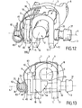
- the anti-rotation elastic element of support 7 is arranged so that at the end of tightening the screw of 3 in the tightening nut 4, said screw tightening 3 neutralises the antirotation function of the anti-rotation elastic element of support 7 (see Figures 12 and 13), to allow the nut to tightening 4 to escape the axial abutment of prepositioning 10 and come jam the caliper 1 on tree 2, as shown on the Figures 14, 2 and 15.
- the axial abutment of prepositioning referenced 101 is integrated with the stirrup 1.
- the axial prepositioning stop 10 is integrated to the elastic antirotation support element 7.
- the attachment portion 71 of the elastic antirotation support element 7 is shaped according to a U-section with two branches 75, 76 and a connection base 74 to to surround the outer part of the stirrup.
- Each of the two branches 75, 76 has a curved end 77, 78 who engages in a housing 13, 14 laid out on the corresponding branch 11, 12 of the stirrup 1.
- the connection flange 74 has two tabs bearing elastics 79 and 80, which are opposite one to the other in the axial direction.
- the antirotation portion of support 72 of the element elastic anti-rotation support 7 has two anti-rotation support tabs 83 and 84, which are connected to each other by an end base 82.
- the flexible link portion 73 of the element elastic antirotation support has two branches flexible 87 and 88 which are connected on the one hand to the connection base 74 of the portion 71 and on the other hand to the tongue corresponding support antirotation 83, 84.
- the axial prepositioning stop 10 is integrated into branch 76 of the snap portion 71 of the elastic support antirotation element 7.
- the clamping nut 4 has a threaded hole 57 which cooperates, with the threaded portion 34.
- a hole passage 56 allows the clamping screw 3 to engage in the tightening nut 4.
- the end cylindrical inner 43 has a cylindrical surface 55 which is eccentric with respect to said cylindrical body 41, so that said cylindrical end internal eccentric 43 is disposed on the opposite side to the shaft 2 relative to the clamping axis 6, when the clamping and locking assembly is in position unlocked (see Figures 8 and 9).
- This eccentricity is arranged so that end of tightening the clamping screw 3 in the nut of tightening 4, and after neutralization of the function antirotation of the antirotation elastic element 7, said clamping nut 4 can rotate around the clamping axis 6, and that the end cylindrical internal eccentric 43 come to rest against the flat 26 arranged on the shaft 2 (see Figures 14 and 15).
- the anti-rotation portion 45 is the extension axial of said cylindrical support base 44. Said anti-rotation portion 45 has two flats 47, 48 : the first flat 47 and the second flat 48 being substantially parallel to each other.
- the outer cylindrical end 46 extends axially the antirotation portion 45, and the transversal size of said end cylindrical outer 46 does not exceed the distance between the first flat 47 and the second flat 48.
- the cylindrical support base 44 has an outer face 51 against which come the two anti-rotation support tongues 83 and 84.
- the portion antirotation 45 has an outer face 52, which must be released at the end of tightening by the anti-rotation portion 72.
- the internal cylindrical end 43 of the nut 4 is eccentric to the body cylindrical 41, so that said end inner cylindrical 43 and said cylindrical body 41 have a common generator 58, which is arranged the opposite side to the shaft 2 with respect to the axis of tightening 6, when the clamping and blocking is in the unlocked position (see figure 9).
- the eccentric internal cylindrical end 43 of the clamping nut 4 is provided with an inclined face 54 relative to the clamping axis 6 to allow the engagement of the tree 2 following a direction parallel to the uprights 11, 12 of the stirrup 1.
- the stirrup 1 thus equipped is engaged on the shaft 2, as shown in Figure 7.
- the tree 2 pushes the inclined face 54 of the end internal cylindrical eccentric 43.
- the tightening nut 4 withdraws to the outside thanks to the flexibility of the elastic antirotation support element 7, and leaves to pass the tree 2 which comes to lean against the face internal 23 of the connecting portion 21.
- the nut clamp 4 then returns to the previous position in support against the axial prepositioning stop 10, as shown in Figure 8.
- the screw 3 is then presented along the axis of tightening 6 as shown in Figure 9.
- the clamping screw 4 is then engaged in the branches 11 and 12 and in the through hole 56 of the tightening nut 4 until the flange 32 applies against the outer face 17. During this operation, the clamping screw 3 pushes back the nut tightening outside the stirrup 1, as is shown in Figures 10 and 11.
- the clamping screw 3 then screws into the threaded hole 57 of the tightening nut 4, which move closer to branch 12 until the support antirotation tongue 83 and 84 escape of the anti-rotation portion 45 of the clamping nut 4 (see Figures 12 and 13).
- This release is realized thanks to the action of the transverse face 36 of the end 35 of the clamping screw 3, which pushes back the end base 82 thus causing the anti-rotation support tabs 83 and 84.
- the clamping screw 4 then rotates the tightening nut 4 with its internal end 43, which comes against the flat 26 of the tree 2; and the tightening nut 4 turning, cleared its radial protrusion 9 of the abutment of prepositioning 10, as shown on Figure 14.
Abstract
Description
La présente invention se rapporte au dispositif d'assemblage d'un étrier avec un arbre, et l'invention concerne plus particulièrement le dispositif d'assemblage d'un étrier de colonne de direction avec un pignon de direction d'un véhicule automobile, qui constitue le raccordement de la colonne de direction avec le boítier de direction.The present invention relates to the device assembling a stirrup with a shaft, and the invention relates more particularly to assembly device of a column stirrup steering with a steering gear of a vehicle automobile, which constitutes the connection of the steering column with the steering box.
Il existe de nombreux dispositifs d'assemblage d'une colonne de direction avec le pignon du boítier de direction d'un véhicule automobile. Lorsque la colonne de direction est munie à sa partie inférieure d'un étrier, il est très fréquent que cet étrier soit équipé d'un boulon, qui se monte transversalement par rapport à l'axe de l'étrier.There are many assembly devices of a steering column with the gear of the housing direction of a motor vehicle. When the steering column is provided at its lower part of a stirrup, it is very common that this stirrup is equipped with a bolt, which is mounted transversely relative to the axis of the stirrup.
Le boulon permet de serrer les deux branches de l'étrier contre l'arbre du pignon de direction, en s'appuyant sur chacune des faces externes des branches dudit étrier. Ces types de dispositifs d'assemblage exigent un environnement dans le véhicule qui permette un accès facile lors du montage et du serrage ; et de plus il est nécessaire de prévoir un outillage spécifique qui permette la présentation correcte de l'écrou lors du montage et de l'engagement de la vis, et qui assure le maintien en rotation de l'écrou lors du serrage. Enfin, ces types de dispositifs d'assemblage ne garantissent par le maintien du serrage lors de l'utilisation du véhicule.The bolt makes it possible to tighten the two branches of the caliper against the pinion shaft, in relying on each of the external faces of branches of said stirrup. These types of devices assembly require an environment in the vehicle that allows easy access during assembly and tightening; and moreover it is necessary to provide specific tools that allow the correct presentation of the nut during assembly and the engagement of the screw, and that ensures the maintenance in rotation of the nut during tightening. Finally, these types of fasteners do not guarantee by maintaining clamping when using the vehicle.
Le but de la présente invention est de proposer un dispositif d'assemblage d'un étrier de colonne de direction avec un pignon de direction, qui évite les inconvénients décrits ci-dessus, et qui permette un montage particulièrement aisé en aveugle dans un encombrement réduit et sans outillage spécifique, tout en garantissant la permanence de l'assemblage.The purpose of the present invention is to propose a device for assembling a column stirrup direction with a pinion steering, which avoids disadvantages described above, and which allows a particularly easy assembly blind in a reduced size and without specific tools, while guaranteeing the permanence of the assembly.
Selon un mode de réalisation de l'invention, ladite invention se rapporte à un dispositif d'assemblage d'un étrier avec l'extrémité d'un arbre, qui vient s'engager dans ledit étrier. Ledit dispositif d'assemblage comprend un ensemble de serrage et de blocage de l'arbre dans l'étrier, qui est constitué par une vis de serrage coopérant avec un écrou de serrage, suivant un axe de serrage. Dans cette configuration :
- l'écrou de serrage est disposé dans l'une des deux branches dudit étrier ;
- la vis de serrage traverse l'autre branche de l'étrier ;
- l'écrou de serrage est maintenu en place en
rotation et en translation suivant l'axe de serrage,
par un élément élastique antirotation d'appui de
l'écrou de serrage contre la face externe de ladite
branche de l'étrier (ces caractéristiques du préambule
de la
revendication 1 sont connues du brevet US-A-4 900 178); ledit dispositif est caractérisé en ce que: - l'écrou de serrage est muni d'une excroissance radiale disposée à sa périphérie externe ;
- une butée axiale de prépositionnement est agencée de façon à être rendue solidaire de l'étrier ;
- afin que, lorsque l'excroissance radiale de 30 l'écrou de serrage vient s'appliquer contre la butée axiale de prépositionnement, ledit écrou de serrage soit dans une position retirée en partie le long de son axe pour autoriser l'engagement de l'étrier sur l'extrémité de l'arbre ;
- ledit élément élastique antirotation d'appui étant agencé de manière qu'en fin de serrage de la vis de serrage dans l'écrou de serrage, ladite vis de serrage neutralise la fonction antirotation de l'élément élastique antirotation d'appui, afin de permettre à l'écrou de serrage de s'échapper de la butée axiale de prépositiionnement et de venir bloquer l'étrier sur l'arbre.
- the clamping nut is arranged in one of the two branches of said stirrup;
- the clamping screw passes through the other branch of the stirrup;
- the clamping nut is held in place in rotation and in translation along the clamping axis, by a resilient anti-rotation element for supporting the clamping nut against the external face of said stirrup branch (these characteristics of the the preamble of
claim 1 are known from US-A-4900178); said device is characterized in that: - the clamping nut is provided with a radial protuberance disposed at its outer periphery;
- an axial prepositioning stop is arranged to be secured to the stirrup;
- so that, when the radial protrusion of the clamping nut engages against the prepositioning axial stop, said clamping nut is in a partially withdrawn position along its axis to allow engagement of the clamping nut; stirrup on the end of the tree;
- said elastic antirotation support member being arranged in such a way that, at the end of tightening of the clamping screw in the clamping nut, said clamping screw counteracts the antirotation function of the elastic antirotation support element, in order to allow the clamping nut to escape from the axial stop prepositiionnement and come block the caliper on the shaft.
Selon un type de réalisation de l'invention, la butée axiale de prépositionnement est intégrée à l'élément élastique antirotation d'appui. Selon un autre type de réalisation de l'invention, la butée axiale de prépositionnement est intégrée à l'étrier.According to one embodiment of the invention, the Axial prepositioning thrust is built into the anti-rotation elastic support element. According to one another type of embodiment of the invention, the stop axial prepositioning is integrated into the stirrup.
Dans une structure générale de réalisation de l'invention, l'écrou de serrage comporte :
- un corps cylindrique qui se monte dans un trou agencé dans la branche de l'étrier correspondante ;
- une collerette d'appui contre la face externe de ladite branche de l'étrier ;
- l'excroissance radiale, qui est disposée à la périphérie de la collerette d'appui, et qui vient s'appliquer contre la butée axiale de prépositionnement lors de l'engagement de l'étrier sur l'extrémité de l'arbre ;
- une extrémité cylindrique interne qui prolonge ledit corps cylindrique dans le logement de l'étrier ; ladite extrémité cylindrique interne étant excentrée par rapport audit corps cylindrique de manière que ladite extrémité cylindrique interne excentrée soit disposée du côté opposé à l'arbre par rapport à l'axe de serrage lorsque l'ensemble de serrage et de blocage est en position déverrouillée ;
- de façon qu'en fin de serrage de la vis de serrage dans l'écrou de serrage, et après neutralisation de la fonction antirotation de l'élément élastique antirotation d'appui, ledit écrou de serrage puisse tourner autour de l'axe de serrage, et que l'extrémité cylindrique interne excentrée vienne s'appuyer contre un méplat aménagé sur l'arbre.
- a cylindrical body which mounts in a hole arranged in the branch of the corresponding stirrup;
- a support flange against the outer face of said yoke leg;
- the radial protuberance, which is disposed at the periphery of the bearing flange, and which is pressed against the axial prepositioning abutment when the stirrup is engaged on the end of the shaft;
- an inner cylindrical end which extends said cylindrical body in the housing of the stirrup; said inner cylindrical end being eccentric with respect to said cylindrical body so that said eccentric inner cylindrical end is disposed opposite to the shaft with respect to the clamping axis when the clamping and locking assembly is in the unlocked position;
- so that at the end of tightening of the clamping screw in the clamping nut, and after neutralization of the antirotation function of the elastic antirotation support element, said clamping nut can rotate around the clamping axis , and that the eccentric internal cylindrical end comes to rest against a flat part arranged on the tree.
Selon une structure générale de réalisation de l'invention, l'élément élastique antirotation d'appui comporte :
- une portion d'accrochage avec l'étrier ;
- une portion antirotation d'appui ;
- une portion souple de liaison raccordant la portion antirotation d'appui à la portion d'accrochage de façon à constituer un seul et même élément.
- a hooking portion with the stirrup;
- a support antirotation portion;
- a flexible connecting portion connecting the anti-rotation support portion to the attachment portion so as to constitute a single element.
Dans une structure détaillée dudit élément élastique antirotation d'appui :
- la portion d'accrochage de l'élément élastique antirotation d'appui est conformée suivant une section en U avec deux branches et une embase de raccordement afin d'entourer la partie externe de l'étrier, chacune des deux branches ayant une extrémité recourbée qui s'engage dans un logement aménagé sur la branche correspondante de l'étrier ; ladite embase de raccordement comportant deux languettes élastique d'appui, qui sont opposées l'une à l'autre dans le sens axial ;
- la portion antirotation d'appui de l'élément élastique antirotation d'appui comporte deux languettes antirotation d'appui qui sont reliées l'une à l'autre par une embase d'extrémité ;
- la portion souple de liaison de l'élément élastique antirotation d'appui, comporte deux branches souples qui sont raccordées d'une part à l'embase de raccordement de la portion d'accrochage et d'autre part à la languette antirotation d'appui correspondante.
- the hooking portion of the resilient antirotation support element is shaped in a U-shaped section with two branches and a connection base to surround the outer part of the stirrup, each of the two branches having a curved end which engages in a housing fitted out on the corresponding branch of the stirrup; said connection base having two resilient support tongues, which are opposite to each other in the axial direction;
- the antirotation support portion of the elastic support antirotation element comprises two support anti-rotation tabs which are connected to one another by an end base;
- the flexible connecting portion of the elastic antirotation support element comprises two flexible branches which are connected on the one hand to the connection base of the attachment portion and on the other hand to the support antirotation tongue corresponding.
Avantageusement, la butée axiale de prépositionnement est intégrée à l'une des branches de la portion d'accrochage de l'élément élastique antirotation d'appui.Advantageously, the axial stop of prepositioning is integrated into one of the branches of the attachment portion of the elastic element antirotation support.
Dans une structure détaillée de l'écrou de serrage :
- la collerette de l'écrou de serrage comporte :
- une embase cylindrique d'appui,
- une portion antirotation qui est le prolongement axial de ladite embase cylindrique d'appui, ladite portion antirotation comporte deux méplats : le premier méplat et le deuxième méplat étant sensiblement parallèles l'un par rapport à l'autre;
- une extrémité cylindrique externe prolonge axialement la portion antirotation, l'encombrement transversal de ladite extrémité cylindrique externe ne dépassent pas la distance entre le premier méplat et le deuxième méplat.
- the collar of the tightening nut comprises:
- a cylindrical support base,
- an antirotation portion which is the axial extension of said cylindrical support base, said antirotation portion comprises two flats: the first flat and the second flat being substantially parallel to each other;
- an outer cylindrical end axially extends the anti-rotation portion, the transverse size of said outer cylindrical end do not exceed the distance between the first flat and the second flat.
De manière qu'au repos, c'est-à-dire avant le serrage, les deux languettes antirotation d'appui de la portion antirotation d'appui s'appliquent contre la face externe de l'embase cylindrique d'appui de la collerette ;
- et qu'en fin de serrage, l'extrémité de la vis de serrage repousse l'embase d'extrémité qui entraíne axialement les deux languettes antirotation d'appui pour les dégager de la portion antirotation.
- and that at the end of tightening, the end of the clamping screw pushes the end base which drives axially the two support anti-rotation tabs to disengage them from the anti-rotation portion.
Avantageusement, l'extrémité cylindrique interne excentrée de l'écrou de serrage est munie d'une face inclinée par rapport à l'axe de serrage, afin de permettre l'engagement de l'arbre suivant une direction parallèle aux montants de l'étrier.Advantageously, the internal cylindrical end eccentric of the clamping nut is provided with a face inclined relative to the clamping axis, in order to allow the engagement of the tree following a direction parallel to the caliper amounts.
De plus, l'extrémité cylindrique interne de l'écrou est excentrée par rapport au corps cylindrique, de manière que ladite extrémité cylindrique interne et ledit corps cylindrique aient une génératrice commune, qui soit disposée du côté opposé à l'arbre par rapport à l'axe de serrage, lorsque l'ensemble de serrage et de blocage est en position déverrouillée.In addition, the internal cylindrical end of the nut is eccentric to the body cylindrical, so that said end inner cylindrical and said cylindrical body a common generator, which is arranged on the side opposite to the shaft with respect to the clamping axis, when the clamping and locking assembly is in unlocked position.
Une application particulièrement intéressante de l'invention se rapporte à une colonne de direction d'un véhicule automobile, dans laquelle l'étrier est monté sur ladite colonne de direction et l'arbre appartient au pignon du boítier de direction.A particularly interesting application of the invention relates to a steering column of a motor vehicle, in which the caliper is mounted on said steering column and the shaft belongs to the gearbox gearbox.
Le dispositif d'assemblage d'un étrier de colonne de direction avec un pignon de direction d'un véhicule automobile selon l'invention présente ainsi l'avantage de permettre un montage avec l'écrou de serrage, qui est maintenu en position ; ce qui évite tout risque de perte et autorise l'assemblage en aveugle dans un encombrement réduit. De plus la position verrouillée avec blocage de l'écrou contre l'arbre garantit le maintien en position de l'étrier sur l'arbre avec le serrage demandé.The assembly device of a caliper steering column with a steering gear of a motor vehicle according to the invention thus presents the advantage of allowing an assembly with the nut of clamping, which is held in position; which avoids any risk of loss and allows assembly in blind in a small footprint. In addition, locked position with nut lock against the shaft guarantees the maintenance in position of the stirrup on the shaft with the required tightening.
D'autres caractéristiques et avantages de la présente invention apparaítront plus clairement à la lecture de la description suivante de plusieurs réalisations préférées de l'invention en référence aux dessins annexés correspondants dans lesquels :
- la figure 1 est une vue en perspective de l'étrier avec l'écrou de serrage et l'élément élastique antirotation d'appui du dispositif d'assemblage selon l'invention ; l'étrier équipé étant prêt à être monté sur l'arbre ;
- la figure 1A est une vue partielle de la figure A relative à une variante de réalisation ;
- la figure 2 est une vue en perspective analogue à la figure 1 en fin d'assemblage de l'étrier avec l'arbre après blocage et serrage ;
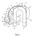
- la figure 3 est une vue suivant III de la figure 1 ;
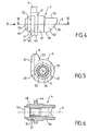
- la figure 4 est une vue de l'écrou de serrage monté dans l'étrier représenté sur la figure 1 ;
- la figure 5 est une vue suivant V de la figure 4 ;
- la figure 6 est une coupe axiale suivant VI-VI de la figure 4 ;
- la figure 7 est une vue analogue à la figure 3 en phase d'engagement de l'étrier sur l'arbre représenté en coupe transversale ;
- la figure 8 est une vue analogue à la figure 3 en fin d'engagement de l'étrier sur l'arbre ;
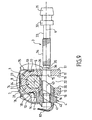
- la figure 9 est une coupe transversale d'une vue analogue à la figure 8 avec présentation de la vis de serrage ;
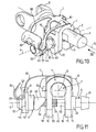
- la figure 10 est une vue en perspective analogue à la figure 1 après engagement de la vis de serrage dans l'étrier ;
- la figure 11 est une vue suivant XI de la figure 10 ;
- la figure 12 est une vue en perspective après dégagement de l'antirotation de l'écrou de serrage par la vis de serrage ;
- la figure 13 est une vue suivant XIII de la figure 12 ;
- la figure 14 est une vue analogue à la figure 13 avec l'écrou de serrage en début d'antirotation par action sur l'arbre ; et
- la figure 15 est une vue suivant XV de la figure 2 après blocage et serrage de l'étrier et de l'arbre.
- Figure 1 is a perspective view of the caliper with the clamping nut and the elastic anti-rotation bearing element of the assembly device according to the invention; the equipped caliper being ready to be mounted on the shaft;
- Figure 1A is a partial view of Figure A relating to an alternative embodiment;
- Figure 2 is a perspective view similar to Figure 1 at the end of assembly of the yoke with the shaft after locking and clamping;
- Figure 3 is a view along III of Figure 1;
- Figure 4 is a view of the clamping nut mounted in the bracket shown in Figure 1;
- Figure 5 is a view along V of Figure 4;
- Figure 6 is an axial section VI-VI of Figure 4;
- Figure 7 is a view similar to Figure 3 in the engagement phase of the stirrup on the shaft shown in cross section;
- Figure 8 is a view similar to Figure 3 at the end of engagement of the stirrup on the shaft;
- Figure 9 is a cross section of a view similar to Figure 8 with presentation of the clamping screw;
- Figure 10 is a perspective view similar to Figure 1 after engagement of the clamping screw in the stirrup;
- Figure 11 is a view along XI of Figure 10;
- Figure 12 is a perspective view after disengagement of the antirotation of the clamping nut by the clamping screw;
- Figure 13 is a view along XIII of Figure 12;
- Figure 14 is a view similar to Figure 13 with the clamping nut at the beginning of antirotation by action on the shaft; and
- Figure 15 is a view along XV of Figure 2 after locking and clamping the stirrup and the shaft.
Le dispositif de l'invention se rapporte à un
assemblage d'un étrier 1 avec un arbre 2 comme cela
est représenté sur les figures 2 et 15. Une
application particulièrement intéressante de
l'invention se rapporte à une colonne de direction
d'un véhicule automobile dans laquelle l'étrier 1 est
monté sur ladite colonne de direction, et l'arbre 2
appartient au pignon du boítier de direction. Selon
l'invention, le dispositif d'assemblage, qui raccorde
l'étrier 1 de la colonne de direction à l'arbre 2 du
pignon de direction, comprend un ensemble de serrage
et de blocage dudit arbre 2 dans l'étrier 1. Cet
ensemble de serrage et de blocage est essentiellement
constitué par une vis de serrage 3, qui coopère avec
un écrou de serrage 4 suivant un axe de serrage 6.The device of the invention relates to a
assembly of a
L'ensemble de la colonne de direction, qui n'est
pas représenté sur les figures, porte à son extrémité
inférieure un joint universel 8 du type "cardan". Le
joint universel 8 est solidaire d'une part de la
colonne de direction, et d'autre part de l'étrier 1.The entire steering column, which is
not shown in the figures, door at its end
lower a
Le pignon de direction a un axe 5, qui est l'axe
de l'arbre 2. L'axe 5 est de ce fait l'axe
d'assemblage de l'étrier 1 sur l'arbre 2.The steering pinion has an
Comme cela est représenté notamment sur la
figure 9, l'étrier 1 a une section transversale par
rapport à l'axe 5, qui est en forme de U. L'étrier 1
est constitué par deux branches 11 et 12, qui sont
sensiblement parallèles l'une par rapport à l'autre.
Les branches 11 et 12 sont reliées l'une à l'autre
par une portion de raccordement 21 qui a sensiblement
une section en demi-couronne circulaire. Les branches
11 et 12 et la portion de raccordement 21 constituent
le logement 22 de l'étrier 1. La portion de
raccordement 21 a une face externe 24 et une face
interne 23, qui constitue le fond du logement 22 de
l'étrier 1. La face interne 23 a une courbure
sensiblement demi-circulaire et de dimension voisine
de la section circulaire de l'arbre 2. Dans la suite
de la description, on appellera interne l'élément ou
la portion qui est le plus proche du plan passant par
l'axe 5 et parallèle aux branches 11 et 12, et on
appellera externe l'élément qui est le plus éloigné
de ce plan de l'axe 5.As shown in particular on the
FIG. 9, the
La branche 11 a une face externe 17 et une face
interne 19, tandis que la branche 12 a une face
externe 18 et une face interne 20. Un logement 13 est
aménagé sur la face externe 17, et un logement 14 est
aménagé sur la face externe 18. La branche 11 est
munie d'un trou 15, qui permet le passage de la vis
de serrage 3, et la branche 12 comporte un trou 16
qui constitue le logement et le support de l'écrou de
serrage 4. Les trous 15 et 16 sont alignés suivant
l'axe de serrage 6, qui est sensiblement
perpendiculaire aux branches 11 et 12, et plus
précisément aux faces externes 17 et 18 et aux faces
internes 19 et 20.
L'arbre 2 a une section circulaire avec une face
cylindrique 25 (voir la figure 2). Un premier méplat
27 et un deuxième méplat 28 sont agencés sur l'arbre
2, et ils sont sensiblement parallèles l'un par
rapport à l'autre. L'épaisseur de l'arbre 2 entre les
deux méplats 27 et 28 est sensiblement voisine et
légèrement inférieure à la distance entre les deux
faces internes 19 et 20 des branches 11 et 12.The
Un troisième méplat 26 est agencé sur l'arbre 2
de manière que ce troisième méplat 26 soit
sensiblement perpendiculaire au premier méplat 27 et
au deuxième méplat 28.A third flat 26 is arranged on the
La vis de serrage 3 a un corps 33 avec, à l'une
de ses extrémités, une tête 31 munie d'une collerette
32.The clamping
A l'autre extrémité, le corps 33 est équipé
d'une portion filetée 34 avec un embout 35 muni d'une
face transversale 36.At the other end, the
Le trou 15, qui est aménagé dans la branche 11,
est dimensionné de manière à laisser passer librement
la portion filetée 34 de la vis de serrage 3, dont la
collerette 32 vient s'appliquer contre fa face
externe 17 de la branche 11.The
L'écrou de serrage 4 comporte un corps
cylindrique 41 qui se monte dans le trou 16 de la
branche 12 de l'étrier 1. Le trou 16 est dimensionné
de façon que le corps cylindrique 41 s'ajuste
correctement dans ledit trou 16 de la branche 12 qui
supporte l'écrou de serrage 4. Le corps cylindrique
41 se prolonge par une extrémité cylindrique interne
43 qui pénètre dans le logement 22 de l'étrier 1.The tightening
Le corps cylindrique 41 se prolonge à
l'extérieur de la branche 12 par une collerette
d'appui 42, qui s'applique contre la face externe 18
de ladite branche 12.The
Ainsi dans le dispositif d'assemblage de
l'invention, l'écrou de serrage 4 est disposé dans
l'une des deux branches 12 de l'étrier 1 ; et la vis
de serrage 3 traverse l'autre branche 11 de l'étrier
1. So in the assembly device of
the invention, the clamping
Selon une des caractéristiques de l'invention,
l'écrou de serrage 4 est maintenu en place en
rotation et en translation suivant l'axe de serrage
6, lorsque l'ensemble de serrage et de blocage est en
position déverrouillée. Comme cela est représenté sur
la figure 9, le maintien en place en rotation et en
translation est assuré par un élément élastique
antirotation d'appui 7 de l'écrou de serrage 4.According to one of the features of the invention,
the tightening
Selon une autre caractéristique de l'invention,
l'écrou de serrage 4 est muni d'une excroissance
radiale 9 qui est disposée à sa périphérie externe.
De plus, une butée axiale de prépositionnement 10 est
agencée de façon à être rendue solidaire de l'étrier
1.According to another characteristic of the invention,
the tightening
L'excroissance radiale 9 et la butée axiale de
prépositionnement 10 sont conçus et disposés de
manière que, lorsque l'excroissance radiale 9 de
l'écrou de serrage 4 vient s'appliquer contre la
butée axiale de prépositionnement 10, ledit écrou de
serrage 4 soit dans une position retirée en partie le
long de son axe 6 pour autoriser l'engagement de
l'étrier 1 sur l'extrémité de l'arbre 2.The
L'élément élastique antirotation d'appui 7 est
agencé de manière qu'en fin de serrage de la vis de
serrage 3 dans l'écrou de serrage 4, ladite vis de
serrage 3 neutralise la fonction antirotation de
l'élément élastique antirotation d'appui 7 (voir
figures 12 et 13), afin de permettre à l'écrou de
serrage 4 de s'échapper de la butée axiale de
prépositionnement 10 et de venir bloquer l'étrier 1
sur l'arbre 2, comme cela est représenté sur les
figures 14, 2 et 15.The anti-rotation elastic element of
Selon un type de réalisation de l'invention
représenté sur la figure 1A, la butée axiale de
prépositionnement référencée 101 est intégrée à
l'étrier 1.According to one embodiment of the invention
represented in FIG. 1A, the axial abutment of
prepositioning referenced 101 is integrated with
the
Selon un autre type de réalisation de
l'invention représenté sur toutes les autres figures,
la butée axiale de prépositionnement 10 est intégrée
à l'élément élastique antirotation d'appui 7.According to another type of embodiment of
the invention shown in all the other figures,
the
L'élément élastique antirotation d'appui 7, qui est représenté sur les différentes figures, comporte:
une portion d'accrochage 71avec l'étrier 1 ;- une
portion antirotation d'appui 72 ; - une portion souple de
liaison 73 raccordant laportion antirotation d'appui 72 à laportion d'accrochage 71 de façon à constituer un seul et même élément.
- a hooking
portion 71 with thestirrup 1; - a
support antirotation portion 72; - a flexible connecting
portion 73 connecting thebearing antirotation portion 72 to theattachment portion 71 so as to constitute one and the same element.
Comme cela est représenté notamment sur les
figures 1, 2 et 9, la portion d'accrochage 71 de
l'élément élastique antirotation d'appui 7 est
conformée suivant une section en U avec deux branches
75, 76 et une embase de raccordement 74 afin
d'entourer la partie externe de l'étrier. Chacune des
deux branches 75, 76 a une extrémité recourbée 77, 78
qui s'engage dans un logement 13, 14 aménagé sur la
branche correspondante 11, 12 de l'étrier 1.
L'embrase de raccordement 74 comporte deux languettes
élastiques d'appui 79 et 80, qui sont opposées l'une
à l'autre dans le sens axial.As is shown in particular on
FIGS. 1, 2 and 9, the
La portion antirotation d'appui 72 de l'élément
élastique antirotation d'appui 7 comporte deux
languettes antirotation d'appui 83 et 84, qui sont
reliées l'une à l'autre par une embase d'extrémité
82.The antirotation portion of
La portion souple de liaison 73 de l'élément
élastique antirotation d'appui comporte deux branches
souples 87 et 88 qui sont raccordées d'une part à
l'embase de raccordement 74 de la portion
d'accrochage 71 et d'autre part à la languette
antirotation d'appui correspondante 83, 84.The
La butée axiale de prépositionnement 10 est
intégrée à la branche 76 de la portion d'accrochage
71 de l'élément élastique antirotation d'appui 7.The
La structure détaillée de l'écrou de serrage 4 est particulièrement mis en évidence sur les figures 4, 5 et 6. Dans cette structure, l'écrou de serrage 4 comporte :
- le corps cylindrique 41 qui se monte dans le trou 16 agencé dans la branche correspondante 12 de l'étrier 1 ;
- la collerette d'appui 42 contre
la face externe 18 de ladite branche 12 de l'étrier 1 ; l'excroissance radiale 9, qui est disposée à la périphérie de la collerette d'appui 42, et qui vient s'appliquer contre la butée axiale de prépositionnement 10 lors de l'engagement de l'étrier 1 sur l'extrémité de l'arbre 2 ;- et l'extrémité cylindrique interne 43 qui
prolonge ledit corps cylindrique 41 dans le logement
22
de l'étrier 1.
- the
cylindrical body 41 which mounts in thehole 16 arranged in the correspondingbranch 12 of thestirrup 1; - the
support flange 42 against theouter face 18 of saidbranch 12 of thestirrup 1; - the
radial protuberance 9, which is disposed at the periphery of the bearingflange 42, and which is pressed against theaxial prepositioning abutment 10 during the engagement of thestirrup 1 on the end of thetree 2; - and the inner
cylindrical end 43 which extends saidcylindrical body 41 in thehousing 22 of thestirrup 1.
L'écrou de serrage 4 a un trou fileté 57 qui
coopère, avec la portion filetée 34. De plus un trou
de passage 56 permet à la vis de serrage 3 de
s'engager dans l'écrou de serrage 4. L'extrémité
cylindrique interne 43 a une surface cylindrique 55
qui est excentrée par rapport audit corps cylindrique
41, de manière que ladite extrémité cylindrique
interne excentrée 43 soit disposée du côté opposé à
l'arbre 2 par rapport à l'axe de serrage 6, lorsque
l'ensemble de serrage et de blocage est en position
déverrouillée (voir figures 8 et 9). The clamping
Cette excentricité est agencée de façon qu'en
fin de serrage de la vis de serrage 3 dans l'écrou de
serrage 4, et après neutralisation de la fonction
antirotation de l'élément élastique antirotation
d'appui 7, ledit écrou de serrage 4 puisse tourner
autour de l'axe de serrage 6, et que l'extrémité
cylindrique interne excentrée 43 vienne s'appuyer
contre le méplat 26 aménagé sur l'arbre 2 (voir
figures 14 et 15).This eccentricity is arranged so that
end of tightening the clamping
Dans cette structure, la collerette 42 de l'écrou de serrage 4 comporte :
- une embase cylindrique d'appui 44,
une portion antirotation 45,- et une extrémité cylindrique externe 46.
- a
cylindrical support base 44, - an
antirotation portion 45, - and an outer
cylindrical end 46.
La portion antirotation 45 est le prolongement
axial de ladite embase cylindrique d'appui 44. Ladite
portion antirotation 45 comporte deux méplats 47, 48
: le premier méplat 47 et le deuxième méplat 48 étant
sensiblement parallèles l'un par rapport à l'autre.The
L'extrémité cylindrique externe 46 prolonge
axialement la portion antirotation 45, et
l'encombrement transversal de ladite extrémité
cylindrique externe 46 ne dépasse pas la distance
entre le premier méplat 47 et le deuxième méplat 48.
L'embase cylindrique d'appui 44 a une face externe 51
contre laquelle viennent s'appliquer les deux
languettes antirotation d'appui 83 et 84. La portion
antirotation 45 a une face externe 52, qui doit être
dégagée en fin de serrage par la portion antirotation
d'appui 72.The outer
Ceci est agencé de manière qu'au repos, c'est-à-dire
avant le serrage, les deux languettes
antirotation d'appui 83, 84 de la portion
antirotation d'appui 72 s'appliquent contre la face
externe 51 de l'embase cylindrique d'appui 44 de la
collerette 42.This is arranged so that at rest, that is to say
before tightening, the two
Ceci est agencé également pour qu'en fin de
serrage, la face transversale 36 de l'extrémité 35 de
la vis de serrage 3 repousse l'embrase d'extrémité 82
qui entraíne axialement les deux languettes
antirotation 83, 84 pour les dégager de la face
externe 52 de la portion antirotation 45 (voir
figures 12 et 13).This is arranged also so that at the end of
tightening, the
Dans le mode de réalisation représenté sur les
différentes figures, l'extrémité cylindrique interne
43 de l'écrou 4 est excentrée par rapport au corps
cylindrique 41, de manière que ladite extrémité
cylindrique interne 43 et ledit corps cylindrique 41
aient une génératrice commune 58, qui soit disposée
du côté opposé à l'arbre 2 par rapport à l'axe de
serrage 6, lorsque l'ensemble de serrage et de
blocage est en position déverrouillée (voir figure
9).In the embodiment shown on the
different figures, the internal
L'extrémité cylindrique interne excentrée 43 de
l'écrou de serrage 4 est munie d'une face inclinée 54
par rapport à l'axe de serrage 6 afin de permettre
l'engagement de l'arbre 2 suivant une direction
parallèle aux montants 11, 12 de l'étrier 1.The eccentric internal
Ainsi pour effectuer le montage de l'étrier 1
sur l'arbre 2, il faut tout d'abord disposer sur
l'étrier 1 l'élément élastique antirotation d'appui 7
équipé de l'écrou de serrage 4, qui s'engage dans le
trou 16 de la branche 12 de l'étrier 1. Durant cette
opération, l'écrou de serrage 4 est maintenu en
position par l'intermédiaire de ses méplats 47 et 48,
qui reçoivent les languettes antirotation d'appui 83
et 84 s'appliquant contre la face externe 51 de
l'embase cylindrique d'appui 44. So to perform the assembly of the
L'écrou s'engage dans l'étrier jusqu'à ce que
l'excroissance radiale 9 vienne s'appliquer contre la
butée axiale de prépositionnement 10 ou 101, comme
cela est représenté sur les figures 1 et 3.The nut engages in the stirrup until
the
L'étrier 1 ainsi équipé est engagé sur l'arbre
2, comme cela est représenté sur la figure 7. L'arbre
2 repousse la face inclinée 54 de l'extrémité
cylindrique interne excentrée 43. L'écrou de serrage
4 se retire vers l'extérieur grâce à la souplesse de
l'élément élastique antirotation d'appui 7, et laisse
passer l'arbre 2 qui vient s'appuyer contre la face
interne 23 de la portion de raccordement 21. L'écrou
de serrage 4 revient alors à la position précédente
en appui contre la butée axiale de prépositionnement
10, comme cela est représenté sur la figure 8. La vis
de serrage 3 est ensuite présentée suivant l'axe de
serrage 6 comme cela est représenté sur la figure 9.The
La vis de serrage 4 est alors engagée dans les
branches 11 et 12 et dans le trou de passage 56 de
l'écrou de serrage 4 jusqu'à ce que la collerette 32
s'applique contre la face externe 17. Durant cette
opération, la vis de serrage 3 repousse l'écrou de
serrage en dehors de l'étrier 1, comme cela est
représenté sur les figures 10 et 11.The clamping
La vis de serrage 3 se visse ensuite dans le
trou fileté 57 de l'écrou de serrage 4, qui se
rapproche de la branche 12 jusqu'à ce que la
languette antirotation d'appui 83 et 84 s'échappent
de la portion antirotation 45 de l'écrou de serrage 4
(voir figures 12 et 13). Ce dégagement est réalisé
grâce à l'action de la face transversale 36 de
l'extrémité 35 de la vis de serrage 3, qui repousse
l'embase d'extrémité 82 entraínant ainsi les
languettes antirotation d'appui 83 et 84. The clamping
La vis de serrage 4 entraíne alors en rotation
l'écrou de serrage 4 avec son extrémité interne 43,
qui vient s'appliquer contre le méplat 26 de l'arbre
2 ; et l'écrou de serrage 4 en tournant, a dégagé son
excroissance radiale 9 de la butée de
prépositionnement 10, comme cela est représenté sur
la figure 14.The clamping
L'écrou de serrage 4 étant immobilisé en
rotation, la vis de serrage 3 en tournant, rapproche
l'écrou de serrage 4 afin d'appliquer sa collerette
42 contre la face externe 18. La vis de serrage 3 est
enfin tournée jusqu'à ce que le serrage demandé soit
effectué comme cela est représenté sur les figures 2
et 15.The tightening
Claims (11)
- A device for assembling a bracket (1) with the end of a shaft (2) having an axis (5) and that is inserted in said bracket (1), said assembly device including a system for clamping and immobilizing the shaft (2) in the bracket (1), which system is constituted by a clamping bolt (3) cooperating with a clamping nut (4) along a clamping axis (6), in which device:the clamping nut (4) is disposed in one (12) of two branches of said bracket (1);the clamping bolt (3) passes through the other branch (11) of the bracket (1);the clamping nut (4) is held in place against rotation and translation along the clamping axis (6) by an antirotation elastic member (7) for bearing the clamping nut (4) against the outside face (18) of said branch (12) of the bracket (1), characterized in that :the outside periphery of the clamping nut (4) is provided with a radial protrusion (9);an axial prepositioning abutment (10, 101) is adapted to be fastened to the bracket (1) ;so that when the radial protrusion (9) of the clamping nut (4) is pressed against the axial prepositioning abutment (10), said clamping nut (4) is partly withdrawn along its axis (6) to allow the bracket (1) to be engaged over the end of the shaft (2);said bearing antirotation elastic member (7) being adapted so that, at the end of tightening the clamping bolt (3) in the clamping nut (4), said clamping bolt (3) neutralizes the antirotation function of the bearing antirotation elastic member (7) in order to allow the clamping nut (4) to escape from the axial prepositioning abutment (10, 101) and immobilize the bracket (1) on the shaft (2).
- An assembly device according to claim 1, characterized in that the axial prepositioning abutment (10) is integrated with the bearing antirotation elastic member (7).
- An assembly device according to claim 1, characterized in that the axial prepositioning abutment (101) is integrated with the bracket (1).
- An assembly device according to claim 1, characterized in that the clamping nut (4) includes:a cylindrical body (41) adapted to be mounted in a hole (16) formed in a corresponding branch (12) of the bracket (1);a bearing flange (42) against the outside face (18) of said branch (12) of the bracket (1);the radial protrusion (9), which is disposed at the periphery of the bearing flange (42), and which is pressed against the axial prepositioning abutment (10) when engaging the bracket (1) over the end of the shaft (2) ;an inside cylindrical end (43) which extends said cylindrical body (41) into the housing (22) of the bracket (1) ; said inside cylindrical end (43) being eccentric with respect to said cylindrical body (41) so that said eccentric inside cylindrical end (43) is on the opposite side of the shaft (2) to the clamping axis (6) when the clamping and immobilizing system is in an unlocked position;so that at the end of tightening the clamping bolt (3) in the clamping nut (4), and after neutralization of the antirotation function of the bearing antirotation elastic member (7), said clamping nut (4) can turn about the clamping axis (6), and the eccentric inside cylindrical end (43) can be pressed against a flap (26) provided on the shaft (2).
- An assembly device according toany one of preceding claims, characterized in that the bearing antirotation elastic member (7) includes:a connecting portion (71) for connecting it to the bracket (1);a bearing antirotation portion (72);a flexible connecting portion (73) connecting the bearing antirotation portion (72) to the connecting portion (71) to constitute a single member.
- An assembly device according to claim 5, characterized in that:the connecting portion (71) of the bearing antirotation elastic member (7) has a U-shaped section with two branches (75, 76) and a connecting base (74) so as to surround the external part of the bracket, each of the two branches (75, 76) having a curved end (77, 78) which is engaged in a housing (13, 14) formed on the corresponding branch (11, 12) of the bracket (1) said connecting base (74) including two bearing elastic tongues (79, 80) which are opposite each other in the axial direction;the bearing antirotation portion (72) of the bearing antirotation elastic member (7) includes two bearing antirotation tongues (83, 84) which are connected together by an end base (82);the flexible connecting portion (73) of the bearing antirotation elastic member (7) includes two flexible branches (87, 88) which are connected to the connecting base (74) of the connecting portion (71) and to the corresponding bearing antirotation tongue (83, 84).
- An assembly device according to claim 6, characterized in that the axial prepositioning abutment (10) is integrated with the branch (76) of the connecting portion (71) of the bearing antirotation elastic member (7).
- An assembly device according to claim 6 or 7, characterized in that :the flange (42) of the clamping nut (4) includes :a bearing cylindrical base (44),an antirotation portion (45) which is an axial extension of said bearing cylindrical base (44), said antirotation portion (45) includes two flaps (47, 48) : the first flap (47) and the second flap (48) being substantially parallel to each other ;an external cylindrical end (46) which axially extends the antirotation portion (45), the transverse overall size of said outside cylindrical end (46) not exceeding the distance between the first flap and the second flap (47, 48),so that at rest, i.e. before clamping, the two bearing antirotation tongues (83, 84) of the bearing antirotation portion (72) are pressed against the outside face (51) of the bearing cylindrical base (44) of the flange (42);and at the end of clamping the end (35) of the clamping bolt (3) pushes back the end base (82) which entrains the two bearing antirotation tongues (83, 84) in the axial direction to disengage them from the antirotation portion (45).
- An assembly device according to any one of preceding claims, characterized in that the eccentric inside cylindrical end (43) of the clamping nut (4) is provided with a face (54) inclined to the clamping axis (6) to enable insertion of the shaft (2) in a direction parallel to the uprights (11, 12) of the bracket (1).
- An assembly device according to any one of preceding claims, characterized in that the inside cylindrical end (43) of the nut (4) is eccentric to the cylindrical body (41) so that said inside cylindrical end (43) and said cylindrical body (41) have a common generatrix (58) that is disposed on the opposite side of the shaft (2) relative to the clamping axis (6) when the clamping and immobilizing system is in an unlocked position.
- An assembly device according to any one of preceding claims, characterized in that it is applied to a steering column of an automobile vehicle wherein the bracket (1) is mounted on said steering column and the shaft (2) belongs to the gear of the steering box.
Applications Claiming Priority (2)
| Application Number | Priority Date | Filing Date | Title |
|---|---|---|---|
| FR0103489 | 2001-03-14 | ||
| FR0103489A FR2822122B1 (en) | 2001-03-14 | 2001-03-14 | ASSEMBLY OF A STEERING COLUMN BRACKET WITH A DIRECTION PINION OF A MOTOR VEHICLE |
Publications (2)
| Publication Number | Publication Date |
|---|---|
| EP1241072A1 EP1241072A1 (en) | 2002-09-18 |
| EP1241072B1 true EP1241072B1 (en) | 2005-06-15 |
Family
ID=8861130
Family Applications (1)
| Application Number | Title | Priority Date | Filing Date |
|---|---|---|---|
| EP02290290A Expired - Lifetime EP1241072B1 (en) | 2001-03-14 | 2002-02-06 | Connection of a steering column clamp with a motor vehicle steering pinion |
Country Status (8)
| Country | Link |
|---|---|
| US (1) | US6575658B2 (en) |
| EP (1) | EP1241072B1 (en) |
| JP (1) | JP4023185B2 (en) |
| AT (1) | ATE297861T1 (en) |
| BR (1) | BR0200641B1 (en) |
| DE (1) | DE60204613T2 (en) |
| ES (1) | ES2240667T3 (en) |
| FR (1) | FR2822122B1 (en) |
Families Citing this family (22)
| Publication number | Priority date | Publication date | Assignee | Title |
|---|---|---|---|---|
| US7272566B2 (en) * | 2003-01-02 | 2007-09-18 | Dolby Laboratories Licensing Corporation | Reducing scale factor transmission cost for MPEG-2 advanced audio coding (AAC) using a lattice based post processing technique |
| JP2004278698A (en) * | 2003-03-17 | 2004-10-07 | Koyo Seiko Co Ltd | Coupling structure between shaft body and shaft coupling |
| FR2861041B1 (en) * | 2003-10-21 | 2006-12-15 | Nacam France Sas | SYSTEM FOR CONNECTING A STEERING COLUMN TO THE GEAR OF THE STEERING RACK |
| JP2005163866A (en) * | 2003-12-01 | 2005-06-23 | Koyo Seiko Co Ltd | Yoke for universal joint |
| US20050169697A1 (en) * | 2004-02-03 | 2005-08-04 | Timken Us Corporation | Adjustable shaft connector |
| ES2257932A1 (en) * | 2004-08-24 | 2006-08-01 | Melchor Daumal Castellon | Mounting assembly for drive shafts in universal joint yokes |
| JP4441600B2 (en) * | 2005-02-17 | 2010-03-31 | 株式会社ジェイテクト | Misassembly prevention tool and universal joint including the same |
| JP4735974B2 (en) * | 2006-03-30 | 2011-07-27 | 株式会社ジェイテクト | Joint structure of universal joint yoke and shaft |
| CN101501357B (en) * | 2006-08-02 | 2011-10-26 | 光洋机械工业株式会社 | Yoke for universal joint |
| FR2904595B1 (en) * | 2006-08-02 | 2008-10-17 | Renault Sas | CONNECTION DEVICE FOR DIRECTION SYSTEM |
| WO2009138578A1 (en) * | 2008-05-16 | 2009-11-19 | Zf Systemes De Direction Nacam, S.A.S. | Device for adjusting the position of a steering column in an automobile |
| US8246658B2 (en) * | 2010-10-29 | 2012-08-21 | Warsaw Orthopedic, Inc. | Spinal connector assembly |
| US9205859B2 (en) | 2011-09-13 | 2015-12-08 | Steering Solutions Ip Holding Corporation | Intermediate shaft connection assurance device |
| US9290198B2 (en) * | 2012-06-19 | 2016-03-22 | GM Global Technology Operations LLC | Fully engaged joint assembly |
| US9086097B2 (en) * | 2012-11-21 | 2015-07-21 | GM Global Technology Operations LLC | Universal joint |
| US9663133B2 (en) | 2013-02-15 | 2017-05-30 | Steering Solutions Ip Holding Corporation | Intermediate shaft for steering column with bearing and lock sleeve |
| FR3006400B1 (en) * | 2013-05-29 | 2015-06-19 | Zf Systemes De Direction Nacam Sas | SECURE ASSEMBLY OF TWO PIECES BY VISSAGE |
| US9545942B2 (en) * | 2014-07-16 | 2017-01-17 | Steering Solutions Ip Holding Corporation | Assembly detection means |
| CN108869560B (en) * | 2018-08-29 | 2023-12-19 | 浙江正昌锻造股份有限公司 | Universal joint fork |
| US11305808B2 (en) * | 2020-06-22 | 2022-04-19 | Steering Solutions Ip Holding Corporation | Steering shaft clamp yoke with bolt blocking component |
| US11407440B1 (en) * | 2021-02-26 | 2022-08-09 | Nissan North America, Inc. | Steering column assembly with protective clip |
| CN113212537A (en) * | 2021-05-14 | 2021-08-06 | 神龙汽车有限公司 | Novel steering column lower yoke and steering engine input shaft connecting mechanism |
Family Cites Families (8)
| Publication number | Priority date | Publication date | Assignee | Title |
|---|---|---|---|---|
| FR2547372B1 (en) * | 1983-06-13 | 1985-08-30 | Nacam | DEVICE FOR DETECTING THE POSITION OF A SHAFT IN A COUPLING ELEMENT, IN PARTICULAR A CARDAN JOINT JAW |
| FR2625538B1 (en) * | 1987-12-31 | 1991-08-16 | Nacam | COUPLING DEVICE AND ITS APPLICATION IN PARTICULAR TO AN AUTOMOTIVE STEERING |
| DE4006787C1 (en) * | 1990-03-03 | 1991-09-19 | Etablissement Supervis, Vaduz, Li | |
| US5253949A (en) * | 1992-07-21 | 1993-10-19 | Trw Inc. | Fail-safe universal joint connection |
| US5503374A (en) * | 1994-05-25 | 1996-04-02 | Maclean-Fogg Company | Self-adjusting shim |
| US6155739A (en) * | 1997-07-02 | 2000-12-05 | Nsk Ltd. | Temporary connection device for universal joint |
| US6443650B2 (en) * | 2000-02-03 | 2002-09-03 | Nsk Ltd. | Connection structure of lateral insert type yoke and shaft |
| US6474917B2 (en) * | 2000-06-22 | 2002-11-05 | Jacques Gauron | Clip nuts |
-
2001
- 2001-03-14 FR FR0103489A patent/FR2822122B1/en not_active Expired - Lifetime
-
2002
- 2002-02-06 ES ES02290290T patent/ES2240667T3/en not_active Expired - Lifetime
- 2002-02-06 EP EP02290290A patent/EP1241072B1/en not_active Expired - Lifetime
- 2002-02-06 AT AT02290290T patent/ATE297861T1/en not_active IP Right Cessation
- 2002-02-06 DE DE60204613T patent/DE60204613T2/en not_active Expired - Lifetime
- 2002-03-06 BR BRPI0200641-3A patent/BR0200641B1/en not_active IP Right Cessation
- 2002-03-11 US US10/093,823 patent/US6575658B2/en not_active Expired - Lifetime
- 2002-03-13 JP JP2002068674A patent/JP4023185B2/en not_active Expired - Fee Related
Also Published As
| Publication number | Publication date |
|---|---|
| JP4023185B2 (en) | 2007-12-19 |
| US20020131820A1 (en) | 2002-09-19 |
| EP1241072A1 (en) | 2002-09-18 |
| BR0200641B1 (en) | 2010-06-01 |
| FR2822122B1 (en) | 2003-05-23 |
| DE60204613D1 (en) | 2005-07-21 |
| JP2002347633A (en) | 2002-12-04 |
| BR0200641A (en) | 2002-12-10 |
| DE60204613T2 (en) | 2006-05-11 |
| US6575658B2 (en) | 2003-06-10 |
| ATE297861T1 (en) | 2005-07-15 |
| FR2822122A1 (en) | 2002-09-20 |
| ES2240667T3 (en) | 2005-10-16 |
Similar Documents
| Publication | Publication Date | Title |
|---|---|---|
| EP1241072B1 (en) | Connection of a steering column clamp with a motor vehicle steering pinion | |
| EP2496849B1 (en) | Self-locking screwing attachment device and assembly provided with same | |
| FR2976987A1 (en) | Assembling device for fixing seat belt return strap on lining part of passenger compartment of vehicle, has screw whose surface exerts constraint on retaining unit to maintain unit in locking position when device is in service configuration | |
| FR2707583A1 (en) | Steering column assembly axially retractable in the event of an impact, in particular for a motor vehicle. | |
| EP0800978B1 (en) | Shock energy absorbing steering column unit,especially for a motor vehicle | |
| EP0086691A1 (en) | Means for fastening the wings of the cap of a front derailleur of a bicycle | |
| WO2009059904A1 (en) | System for fitting a universal joint for connecting the barrel of a bolt to a lock | |
| EP0706929B1 (en) | Device for connecting a motor vehicle steering wheel hub on a steering column | |
| EP0508856A1 (en) | Safety clamping device of a male element in a caliper of a female element, used particularly to join two lengths of the steering column of an automotive vehicle | |
| FR2712049A1 (en) | Device for fastening a member to a steering shaft, particularly of a motor vehicle | |
| EP0774399B1 (en) | System for holding the position of a clamping element | |
| EP3683150B1 (en) | Device for pivoting connection between at least two parts, aircraft comprising a cowl equipped with said pivoting connection device | |
| FR2815924A1 (en) | Automobile steering column caliper and pinion assembly comprises locking screw engaging locking nut in caliper branch, nut held in place by anti-rotation support spring | |
| EP0821171A1 (en) | Bayonet type quick coupling for connecting two vehicle steering parts | |
| EP0296961A1 (en) | Fixing means | |
| FR2745609A1 (en) | BAYONET TYPE QUICK COUPLER | |
| EP1104736B1 (en) | Device for assembling a steering pinion with a yoke | |
| EP1258389B1 (en) | Closure device for an opening in a wall for fastening an object, such as an automotive vehicle seat | |
| EP1092880A1 (en) | Screw-type fastening means allowing adjustment between two elements | |
| FR2751605A1 (en) | DEVICE FOR FIXING A VEHICLE STEERING WHEEL HUB ON AN END OF A STEERING SHAFT | |
| EP0470888A1 (en) | Steering column especially for a motor vehicle | |
| EP3583017A1 (en) | Vehicle, notably motor vehicle, bodywork arrangement | |
| FR2879694A1 (en) | Retaining washer for blocking differential pinion shaft, has central base and is fixed in one bore of differential case in which differential pinion shaft is engaged, to immobilize shaft along with fixation of another washer in another bore | |
| FR2729113A1 (en) | Fixing of steering wheel on steering shaft | |
| EP1637747B1 (en) | Arrangement for fixing of an equipment element for a motor vehicle |
Legal Events
| Date | Code | Title | Description |
|---|---|---|---|
| PUAI | Public reference made under article 153(3) epc to a published international application that has entered the european phase |
Free format text: ORIGINAL CODE: 0009012 |
|
| AK | Designated contracting states |
Kind code of ref document: A1 Designated state(s): AT BE CH CY DE DK ES FI FR GB GR IE IT LI LU MC NL PT SE TR |
|
| AX | Request for extension of the european patent |
Free format text: AL;LT;LV;MK;RO;SI |
|
| 17P | Request for examination filed |
Effective date: 20020921 |
|
| AKX | Designation fees paid |
Designated state(s): AT BE CH CY DE DK ES FI FR GB GR IE IT LI LU MC NL PT SE TR |
|
| GRAP | Despatch of communication of intention to grant a patent |
Free format text: ORIGINAL CODE: EPIDOSNIGR1 |
|
| GRAS | Grant fee paid |
Free format text: ORIGINAL CODE: EPIDOSNIGR3 |
|
| GRAA | (expected) grant |
Free format text: ORIGINAL CODE: 0009210 |
|
| AK | Designated contracting states |
Kind code of ref document: B1 Designated state(s): AT BE CH CY DE DK ES FI FR GB GR IE IT LI LU MC NL PT SE TR |
|
| PG25 | Lapsed in a contracting state [announced via postgrant information from national office to epo] |
Ref country code: AT Free format text: LAPSE BECAUSE OF FAILURE TO SUBMIT A TRANSLATION OF THE DESCRIPTION OR TO PAY THE FEE WITHIN THE PRESCRIBED TIME-LIMIT Effective date: 20050615 Ref country code: IT Free format text: LAPSE BECAUSE OF FAILURE TO SUBMIT A TRANSLATION OF THE DESCRIPTION OR TO PAY THE FEE WITHIN THE PRESCRIBED TIME-LIMIT;WARNING: LAPSES OF ITALIAN PATENTS WITH EFFECTIVE DATE BEFORE 2007 MAY HAVE OCCURRED AT ANY TIME BEFORE 2007. THE CORRECT EFFECTIVE DATE MAY BE DIFFERENT FROM THE ONE RECORDED. Effective date: 20050615 Ref country code: IE Free format text: LAPSE BECAUSE OF FAILURE TO SUBMIT A TRANSLATION OF THE DESCRIPTION OR TO PAY THE FEE WITHIN THE PRESCRIBED TIME-LIMIT Effective date: 20050615 Ref country code: TR Free format text: LAPSE BECAUSE OF FAILURE TO SUBMIT A TRANSLATION OF THE DESCRIPTION OR TO PAY THE FEE WITHIN THE PRESCRIBED TIME-LIMIT Effective date: 20050615 Ref country code: NL Free format text: LAPSE BECAUSE OF FAILURE TO SUBMIT A TRANSLATION OF THE DESCRIPTION OR TO PAY THE FEE WITHIN THE PRESCRIBED TIME-LIMIT Effective date: 20050615 Ref country code: FI Free format text: LAPSE BECAUSE OF FAILURE TO SUBMIT A TRANSLATION OF THE DESCRIPTION OR TO PAY THE FEE WITHIN THE PRESCRIBED TIME-LIMIT Effective date: 20050615 |
|
| REG | Reference to a national code |
Ref country code: CH Ref legal event code: EP Ref country code: GB Ref legal event code: FG4D Free format text: NOT ENGLISH |
|
| REF | Corresponds to: |
Ref document number: 60204613 Country of ref document: DE Date of ref document: 20050721 Kind code of ref document: P |
|
| REG | Reference to a national code |
Ref country code: IE Ref legal event code: FG4D Free format text: LANGUAGE OF EP DOCUMENT: FRENCH |
|
| GBT | Gb: translation of ep patent filed (gb section 77(6)(a)/1977) |
Effective date: 20050725 |
|
| PG25 | Lapsed in a contracting state [announced via postgrant information from national office to epo] |
Ref country code: DK Free format text: LAPSE BECAUSE OF FAILURE TO SUBMIT A TRANSLATION OF THE DESCRIPTION OR TO PAY THE FEE WITHIN THE PRESCRIBED TIME-LIMIT Effective date: 20050915 Ref country code: GR Free format text: LAPSE BECAUSE OF FAILURE TO SUBMIT A TRANSLATION OF THE DESCRIPTION OR TO PAY THE FEE WITHIN THE PRESCRIBED TIME-LIMIT Effective date: 20050915 Ref country code: SE Free format text: LAPSE BECAUSE OF FAILURE TO SUBMIT A TRANSLATION OF THE DESCRIPTION OR TO PAY THE FEE WITHIN THE PRESCRIBED TIME-LIMIT Effective date: 20050915 |
|
| REG | Reference to a national code |
Ref country code: ES Ref legal event code: FG2A Ref document number: 2240667 Country of ref document: ES Kind code of ref document: T3 |
|
| PG25 | Lapsed in a contracting state [announced via postgrant information from national office to epo] |
Ref country code: PT Free format text: LAPSE BECAUSE OF FAILURE TO SUBMIT A TRANSLATION OF THE DESCRIPTION OR TO PAY THE FEE WITHIN THE PRESCRIBED TIME-LIMIT Effective date: 20051124 |
|
| NLV1 | Nl: lapsed or annulled due to failure to fulfill the requirements of art. 29p and 29m of the patents act | ||
| REG | Reference to a national code |
Ref country code: IE Ref legal event code: FD4D |
|
| PG25 | Lapsed in a contracting state [announced via postgrant information from national office to epo] |
Ref country code: CH Free format text: LAPSE BECAUSE OF NON-PAYMENT OF DUE FEES Effective date: 20060228 Ref country code: BE Free format text: LAPSE BECAUSE OF NON-PAYMENT OF DUE FEES Effective date: 20060228 Ref country code: LU Free format text: LAPSE BECAUSE OF NON-PAYMENT OF DUE FEES Effective date: 20060228 Ref country code: LI Free format text: LAPSE BECAUSE OF NON-PAYMENT OF DUE FEES Effective date: 20060228 Ref country code: MC Free format text: LAPSE BECAUSE OF NON-PAYMENT OF DUE FEES Effective date: 20060228 |
|
| PLBE | No opposition filed within time limit |
Free format text: ORIGINAL CODE: 0009261 |
|
| STAA | Information on the status of an ep patent application or granted ep patent |
Free format text: STATUS: NO OPPOSITION FILED WITHIN TIME LIMIT |
|
| 26N | No opposition filed |
Effective date: 20060316 |
|
| REG | Reference to a national code |
Ref country code: CH Ref legal event code: PL |
|
| REG | Reference to a national code |
Ref country code: FR Ref legal event code: ST Effective date: 20061031 |
|
| BERE | Be: lapsed |
Owner name: NACAM FRANCE S.A. Effective date: 20060228 |
|
| PG25 | Lapsed in a contracting state [announced via postgrant information from national office to epo] |
Ref country code: FR Free format text: LAPSE BECAUSE OF NON-PAYMENT OF DUE FEES Effective date: 20060228 |
|
| PG25 | Lapsed in a contracting state [announced via postgrant information from national office to epo] |
Ref country code: CY Free format text: LAPSE BECAUSE OF FAILURE TO SUBMIT A TRANSLATION OF THE DESCRIPTION OR TO PAY THE FEE WITHIN THE PRESCRIBED TIME-LIMIT Effective date: 20050615 |
|
| REG | Reference to a national code |
Ref country code: DE Ref legal event code: R082 Ref document number: 60204613 Country of ref document: DE Representative=s name: JOCHEN MUELLER, DE Ref country code: DE Ref legal event code: R082 Ref document number: 60204613 Country of ref document: DE Representative=s name: MUELLER, JOCHEN, DIPL.-ING., DE |
|
| PGFP | Annual fee paid to national office [announced via postgrant information from national office to epo] |
Ref country code: ES Payment date: 20120224 Year of fee payment: 11 |
|
| REG | Reference to a national code |
Ref country code: ES Ref legal event code: FD2A Effective date: 20140509 |
|
| PG25 | Lapsed in a contracting state [announced via postgrant information from national office to epo] |
Ref country code: ES Free format text: LAPSE BECAUSE OF NON-PAYMENT OF DUE FEES Effective date: 20130207 |
|
| REG | Reference to a national code |
Ref country code: DE Ref legal event code: R082 Ref document number: 60204613 Country of ref document: DE Representative=s name: MUELLER, JOCHEN, DIPL.-ING., DE Ref country code: DE Ref legal event code: R081 Ref document number: 60204613 Country of ref document: DE Owner name: ROBERT BOSCH AUTOMOTIVE STEERING VENDOME SAS, FR Free format text: FORMER OWNER: NACAM FRANCE S.A., VENDOME, FR |
|
| PGFP | Annual fee paid to national office [announced via postgrant information from national office to epo] |
Ref country code: GB Payment date: 20210225 Year of fee payment: 20 |
|
| PGFP | Annual fee paid to national office [announced via postgrant information from national office to epo] |
Ref country code: DE Payment date: 20210420 Year of fee payment: 20 |
|
| REG | Reference to a national code |
Ref country code: GB Ref legal event code: PE20 Expiry date: 20220205 |
|
| PG25 | Lapsed in a contracting state [announced via postgrant information from national office to epo] |
Ref country code: GB Free format text: LAPSE BECAUSE OF EXPIRATION OF PROTECTION Effective date: 20220205 |