EP1241043A1 - Véhicule hybride série capable de fonctionner sans batterie - Google Patents
Véhicule hybride série capable de fonctionner sans batterie Download PDFInfo
- Publication number
- EP1241043A1 EP1241043A1 EP02004997A EP02004997A EP1241043A1 EP 1241043 A1 EP1241043 A1 EP 1241043A1 EP 02004997 A EP02004997 A EP 02004997A EP 02004997 A EP02004997 A EP 02004997A EP 1241043 A1 EP1241043 A1 EP 1241043A1
- Authority
- EP
- European Patent Office
- Prior art keywords
- speed
- vehicle
- heat engine
- control
- torque
- Prior art date
- Legal status (The legal status is an assumption and is not a legal conclusion. Google has not performed a legal analysis and makes no representation as to the accuracy of the status listed.)
- Withdrawn
Links
Images


Classifications
-
- B—PERFORMING OPERATIONS; TRANSPORTING
- B60—VEHICLES IN GENERAL
- B60W—CONJOINT CONTROL OF VEHICLE SUB-UNITS OF DIFFERENT TYPE OR DIFFERENT FUNCTION; CONTROL SYSTEMS SPECIALLY ADAPTED FOR HYBRID VEHICLES; ROAD VEHICLE DRIVE CONTROL SYSTEMS FOR PURPOSES NOT RELATED TO THE CONTROL OF A PARTICULAR SUB-UNIT
- B60W10/00—Conjoint control of vehicle sub-units of different type or different function
- B60W10/04—Conjoint control of vehicle sub-units of different type or different function including control of propulsion units
- B60W10/08—Conjoint control of vehicle sub-units of different type or different function including control of propulsion units including control of electric propulsion units, e.g. motors or generators
-
- B—PERFORMING OPERATIONS; TRANSPORTING
- B60—VEHICLES IN GENERAL
- B60K—ARRANGEMENT OR MOUNTING OF PROPULSION UNITS OR OF TRANSMISSIONS IN VEHICLES; ARRANGEMENT OR MOUNTING OF PLURAL DIVERSE PRIME-MOVERS IN VEHICLES; AUXILIARY DRIVES FOR VEHICLES; INSTRUMENTATION OR DASHBOARDS FOR VEHICLES; ARRANGEMENTS IN CONNECTION WITH COOLING, AIR INTAKE, GAS EXHAUST OR FUEL SUPPLY OF PROPULSION UNITS IN VEHICLES
- B60K6/00—Arrangement or mounting of plural diverse prime-movers for mutual or common propulsion, e.g. hybrid propulsion systems comprising electric motors and internal combustion engines
- B60K6/20—Arrangement or mounting of plural diverse prime-movers for mutual or common propulsion, e.g. hybrid propulsion systems comprising electric motors and internal combustion engines the prime-movers consisting of electric motors and internal combustion engines, e.g. HEVs
- B60K6/22—Arrangement or mounting of plural diverse prime-movers for mutual or common propulsion, e.g. hybrid propulsion systems comprising electric motors and internal combustion engines the prime-movers consisting of electric motors and internal combustion engines, e.g. HEVs characterised by apparatus, components or means specially adapted for HEVs
- B60K6/34—Arrangement or mounting of plural diverse prime-movers for mutual or common propulsion, e.g. hybrid propulsion systems comprising electric motors and internal combustion engines the prime-movers consisting of electric motors and internal combustion engines, e.g. HEVs characterised by apparatus, components or means specially adapted for HEVs characterised by the absence of energy storing means
-
- B—PERFORMING OPERATIONS; TRANSPORTING
- B60—VEHICLES IN GENERAL
- B60K—ARRANGEMENT OR MOUNTING OF PROPULSION UNITS OR OF TRANSMISSIONS IN VEHICLES; ARRANGEMENT OR MOUNTING OF PLURAL DIVERSE PRIME-MOVERS IN VEHICLES; AUXILIARY DRIVES FOR VEHICLES; INSTRUMENTATION OR DASHBOARDS FOR VEHICLES; ARRANGEMENTS IN CONNECTION WITH COOLING, AIR INTAKE, GAS EXHAUST OR FUEL SUPPLY OF PROPULSION UNITS IN VEHICLES
- B60K6/00—Arrangement or mounting of plural diverse prime-movers for mutual or common propulsion, e.g. hybrid propulsion systems comprising electric motors and internal combustion engines
- B60K6/20—Arrangement or mounting of plural diverse prime-movers for mutual or common propulsion, e.g. hybrid propulsion systems comprising electric motors and internal combustion engines the prime-movers consisting of electric motors and internal combustion engines, e.g. HEVs
- B60K6/42—Arrangement or mounting of plural diverse prime-movers for mutual or common propulsion, e.g. hybrid propulsion systems comprising electric motors and internal combustion engines the prime-movers consisting of electric motors and internal combustion engines, e.g. HEVs characterised by the architecture of the hybrid electric vehicle
- B60K6/46—Series type
-
- B—PERFORMING OPERATIONS; TRANSPORTING
- B60—VEHICLES IN GENERAL
- B60L—PROPULSION OF ELECTRICALLY-PROPELLED VEHICLES; SUPPLYING ELECTRIC POWER FOR AUXILIARY EQUIPMENT OF ELECTRICALLY-PROPELLED VEHICLES; ELECTRODYNAMIC BRAKE SYSTEMS FOR VEHICLES IN GENERAL; MAGNETIC SUSPENSION OR LEVITATION FOR VEHICLES; MONITORING OPERATING VARIABLES OF ELECTRICALLY-PROPELLED VEHICLES; ELECTRIC SAFETY DEVICES FOR ELECTRICALLY-PROPELLED VEHICLES
- B60L50/00—Electric propulsion with power supplied within the vehicle
- B60L50/50—Electric propulsion with power supplied within the vehicle using propulsion power supplied by batteries or fuel cells
- B60L50/60—Electric propulsion with power supplied within the vehicle using propulsion power supplied by batteries or fuel cells using power supplied by batteries
- B60L50/61—Electric propulsion with power supplied within the vehicle using propulsion power supplied by batteries or fuel cells using power supplied by batteries by batteries charged by engine-driven generators, e.g. series hybrid electric vehicles
-
- B—PERFORMING OPERATIONS; TRANSPORTING
- B60—VEHICLES IN GENERAL
- B60L—PROPULSION OF ELECTRICALLY-PROPELLED VEHICLES; SUPPLYING ELECTRIC POWER FOR AUXILIARY EQUIPMENT OF ELECTRICALLY-PROPELLED VEHICLES; ELECTRODYNAMIC BRAKE SYSTEMS FOR VEHICLES IN GENERAL; MAGNETIC SUSPENSION OR LEVITATION FOR VEHICLES; MONITORING OPERATING VARIABLES OF ELECTRICALLY-PROPELLED VEHICLES; ELECTRIC SAFETY DEVICES FOR ELECTRICALLY-PROPELLED VEHICLES
- B60L2240/00—Control parameters of input or output; Target parameters
- B60L2240/40—Drive Train control parameters
- B60L2240/44—Drive Train control parameters related to combustion engines
- B60L2240/441—Speed
-
- B—PERFORMING OPERATIONS; TRANSPORTING
- B60—VEHICLES IN GENERAL
- B60L—PROPULSION OF ELECTRICALLY-PROPELLED VEHICLES; SUPPLYING ELECTRIC POWER FOR AUXILIARY EQUIPMENT OF ELECTRICALLY-PROPELLED VEHICLES; ELECTRODYNAMIC BRAKE SYSTEMS FOR VEHICLES IN GENERAL; MAGNETIC SUSPENSION OR LEVITATION FOR VEHICLES; MONITORING OPERATING VARIABLES OF ELECTRICALLY-PROPELLED VEHICLES; ELECTRIC SAFETY DEVICES FOR ELECTRICALLY-PROPELLED VEHICLES
- B60L2240/00—Control parameters of input or output; Target parameters
- B60L2240/40—Drive Train control parameters
- B60L2240/48—Drive Train control parameters related to transmissions
- B60L2240/486—Operating parameters
-
- B—PERFORMING OPERATIONS; TRANSPORTING
- B60—VEHICLES IN GENERAL
- B60W—CONJOINT CONTROL OF VEHICLE SUB-UNITS OF DIFFERENT TYPE OR DIFFERENT FUNCTION; CONTROL SYSTEMS SPECIALLY ADAPTED FOR HYBRID VEHICLES; ROAD VEHICLE DRIVE CONTROL SYSTEMS FOR PURPOSES NOT RELATED TO THE CONTROL OF A PARTICULAR SUB-UNIT
- B60W2510/00—Input parameters relating to a particular sub-units
- B60W2510/06—Combustion engines, Gas turbines
- B60W2510/0638—Engine speed
-
- B—PERFORMING OPERATIONS; TRANSPORTING
- B60—VEHICLES IN GENERAL
- B60W—CONJOINT CONTROL OF VEHICLE SUB-UNITS OF DIFFERENT TYPE OR DIFFERENT FUNCTION; CONTROL SYSTEMS SPECIALLY ADAPTED FOR HYBRID VEHICLES; ROAD VEHICLE DRIVE CONTROL SYSTEMS FOR PURPOSES NOT RELATED TO THE CONTROL OF A PARTICULAR SUB-UNIT
- B60W2540/00—Input parameters relating to occupants
- B60W2540/10—Accelerator pedal position
-
- B—PERFORMING OPERATIONS; TRANSPORTING
- B60—VEHICLES IN GENERAL
- B60W—CONJOINT CONTROL OF VEHICLE SUB-UNITS OF DIFFERENT TYPE OR DIFFERENT FUNCTION; CONTROL SYSTEMS SPECIALLY ADAPTED FOR HYBRID VEHICLES; ROAD VEHICLE DRIVE CONTROL SYSTEMS FOR PURPOSES NOT RELATED TO THE CONTROL OF A PARTICULAR SUB-UNIT
- B60W2710/00—Output or target parameters relating to a particular sub-units
- B60W2710/06—Combustion engines, Gas turbines
- B60W2710/0644—Engine speed
- B60W2710/065—Idle condition
-
- B—PERFORMING OPERATIONS; TRANSPORTING
- B60—VEHICLES IN GENERAL
- B60W—CONJOINT CONTROL OF VEHICLE SUB-UNITS OF DIFFERENT TYPE OR DIFFERENT FUNCTION; CONTROL SYSTEMS SPECIALLY ADAPTED FOR HYBRID VEHICLES; ROAD VEHICLE DRIVE CONTROL SYSTEMS FOR PURPOSES NOT RELATED TO THE CONTROL OF A PARTICULAR SUB-UNIT
- B60W2710/00—Output or target parameters relating to a particular sub-units
- B60W2710/10—Change speed gearings
- B60W2710/105—Output torque
-
- Y—GENERAL TAGGING OF NEW TECHNOLOGICAL DEVELOPMENTS; GENERAL TAGGING OF CROSS-SECTIONAL TECHNOLOGIES SPANNING OVER SEVERAL SECTIONS OF THE IPC; TECHNICAL SUBJECTS COVERED BY FORMER USPC CROSS-REFERENCE ART COLLECTIONS [XRACs] AND DIGESTS
- Y02—TECHNOLOGIES OR APPLICATIONS FOR MITIGATION OR ADAPTATION AGAINST CLIMATE CHANGE
- Y02T—CLIMATE CHANGE MITIGATION TECHNOLOGIES RELATED TO TRANSPORTATION
- Y02T10/00—Road transport of goods or passengers
- Y02T10/60—Other road transportation technologies with climate change mitigation effect
- Y02T10/62—Hybrid vehicles
-
- Y—GENERAL TAGGING OF NEW TECHNOLOGICAL DEVELOPMENTS; GENERAL TAGGING OF CROSS-SECTIONAL TECHNOLOGIES SPANNING OVER SEVERAL SECTIONS OF THE IPC; TECHNICAL SUBJECTS COVERED BY FORMER USPC CROSS-REFERENCE ART COLLECTIONS [XRACs] AND DIGESTS
- Y02—TECHNOLOGIES OR APPLICATIONS FOR MITIGATION OR ADAPTATION AGAINST CLIMATE CHANGE
- Y02T—CLIMATE CHANGE MITIGATION TECHNOLOGIES RELATED TO TRANSPORTATION
- Y02T10/00—Road transport of goods or passengers
- Y02T10/60—Other road transportation technologies with climate change mitigation effect
- Y02T10/70—Energy storage systems for electromobility, e.g. batteries
-
- Y—GENERAL TAGGING OF NEW TECHNOLOGICAL DEVELOPMENTS; GENERAL TAGGING OF CROSS-SECTIONAL TECHNOLOGIES SPANNING OVER SEVERAL SECTIONS OF THE IPC; TECHNICAL SUBJECTS COVERED BY FORMER USPC CROSS-REFERENCE ART COLLECTIONS [XRACs] AND DIGESTS
- Y02—TECHNOLOGIES OR APPLICATIONS FOR MITIGATION OR ADAPTATION AGAINST CLIMATE CHANGE
- Y02T—CLIMATE CHANGE MITIGATION TECHNOLOGIES RELATED TO TRANSPORTATION
- Y02T10/00—Road transport of goods or passengers
- Y02T10/60—Other road transportation technologies with climate change mitigation effect
- Y02T10/7072—Electromobility specific charging systems or methods for batteries, ultracapacitors, supercapacitors or double-layer capacitors
-
- Y—GENERAL TAGGING OF NEW TECHNOLOGICAL DEVELOPMENTS; GENERAL TAGGING OF CROSS-SECTIONAL TECHNOLOGIES SPANNING OVER SEVERAL SECTIONS OF THE IPC; TECHNICAL SUBJECTS COVERED BY FORMER USPC CROSS-REFERENCE ART COLLECTIONS [XRACs] AND DIGESTS
- Y02—TECHNOLOGIES OR APPLICATIONS FOR MITIGATION OR ADAPTATION AGAINST CLIMATE CHANGE
- Y02T—CLIMATE CHANGE MITIGATION TECHNOLOGIES RELATED TO TRANSPORTATION
- Y02T10/00—Road transport of goods or passengers
- Y02T10/60—Other road transportation technologies with climate change mitigation effect
- Y02T10/72—Electric energy management in electromobility
Definitions
- the present invention relates to road motor vehicles, with series hybrid motorization.
- a heat engine drives an electric alternator which transforms the mechanical energy available at the engine shaft into electrical energy.
- This electrical energy powers one or more electric traction motors, connected mechanically to the drive wheels of the vehicle.
- the heat engine is not connected mechanically at the wheels, unlike parallel hybrid vehicles, in both a heat engine and an electric motor are mechanically connected to the drive wheels, the torques they deliver can add up to drive the wheels drive.
- the purpose of the present invention is therefore to design a series hybrid powertrain which can optionally operate without an electric storage battery, while providing the driver of the vehicle a very progressive and very responsive throttle control.
- a series hybrid powertrain which can optionally operate without an electric storage battery, while providing the driver of the vehicle a very progressive and very responsive throttle control.
- the problem is therefore to obtain the desired torque from the electric traction motor while avoiding stalling or the runaway of the engine, and this by means of a control whose progressiveness and responsiveness are as close as possible to that of a vehicle accelerator pedal conventional thermal.
- the heat engine is of any type that can be controlled by a command variable like an accelerator pedal.
- a command variable like an accelerator pedal.
- diesel engines in which the control acts on the quantity of fuel injected into the combustion chamber.
- petrol engines in which the control acts on the amount of air admitted into the combustion chamber.
- the electric traction motor there may be only one, or several, for example one per vehicle wheel. If there are several electric traction motors, it should be understood by "Setpoint torque C" a cumulative overall torque for all the motors, the present invention not concerning the question of the distribution of the torque between the motors.
- the type of electric motor this is a motor whose torque delivered to the shaft can be controlled rotation, amplitude and sign. It is, for example, a self-controlled synchronous machine, flux concentration, inductor with permanent magnets.
- the alternator used is for example an electrical machine of the same type as that proposed. for the electric traction motor.
- the alternator transforms the mechanical energy available to the output shaft of the heat engine into electrical energy consumed by the electrical load connected to the power line on which said alternator outputs (for this presentation, the load electric is mainly the electric traction motor (s).
- the piloting power P proceeds from an evaluation of the power of the available heat engine P thd .
- Said pilot power P is not the exact image of the power actually available P thd to the shaft of the heat engine.
- Various control power curves will be given below as a function of the real speed R, curves which are superimposed on the real curves of available power P thd for different positions of the actuator PP. Since the piloting power P proceeds from an approximation more or less close to reality, the operating point of the heat engine giving a particular power as a function of the real engine speed R does not necessarily correspond to a balance between the power actually available P thd and the power consumed in electrical form by the loads connected to the alternator.
- the setpoint torque C is calculated by successive iterations.
- the accelerator control CA to arrangement of the driver does not act directly on the setpoint torque C of the motor electric traction. It acts on the heat engine.
- the setpoint torque C of the motor electric traction is automatically adapted to the actual operation of the heat engine.
- the accelerator control CA acts directly on the actuator PP.
- Said PP actuator also takes into account the torque absorbed by the electric traction motor because it is necessarily limited, under penalty of destruction of the electric motor in the event of excessive current intense. Indeed, at low vehicle travel speed, saturation is reached (current permissible by the electric motor and the inverter) for low power levels.
- the acceleration request should be clipped from the driver. It is only below the saturation of the electric motor that we can link, for example proportionally, the control of the PP actuator to the control AC accelerator on which the driver acts directly.
- FIG. 1 we see a petrol petrol engine 10, and an actuator 15 controlling the position of a throttle valve in an air intake manifold.
- the heat engine drives a alternator 11.
- the electrical energy supplied by the latter is distributed to four motors traction motors 21, via a rectifier 13, an electric line 12, and an inverter 22 by motor 21.
- An electrical energy absorption device 14 is connected to the line electric 12.
- a central unit 30 manages various functions, among which the electric traction chain of the vehicle (engine or brake torque of electric motors 21).
- Central unit 30 includes a control unit 31 of the propulsion torque of the electric motors 21 and a electronic device 32 for controlling the actuator 15 acting on the position of the butterfly PP, which acts on the power developed by the heat engine 10.
- the control unit 31 of the vehicle propulsion torque calculates said setpoint torque according to a period sampling method.
- the central processing unit 30 receives evaluation signals from different parameters like a potentiometer 40 reflecting the position of an AC accelerator control (a pedal or other equivalent control available to the driver of the vehicle), such as sensor 41 reflecting the position of the throttle valve PP, a sensor 42 giving the speed v of the vehicle, a sensor 43 giving the engine speed R, various temperature sensors 44, one sensor 45 giving the pressure of the vehicle's hydraulic braking circuit, the list being no comprehensive.
- a potentiometer 40 reflecting the position of an AC accelerator control (a pedal or other equivalent control available to the driver of the vehicle)
- sensor 41 reflecting the position of the throttle valve PP
- sensor 42 giving the speed v of the vehicle
- a sensor 43 giving the engine speed R
- various temperature sensors 44 one sensor 45 giving the pressure of the vehicle's hydraulic braking circuit
- peripheral organs absorb the power delivered by the thermal motor.
- the thermal motor With regard to the present invention, it does not matter that they take a mechanical power directly to the crankshaft of the heat engine or that they take a electrical power on power line 12 because this amounts to taking said power at crankshaft via the alternator.
- some of these peripheral organs can also be managed by the central unit 30, which has the advantage of being able to take into account variations in power consumed in the control device 32 of the actuator 15 even before the engine speed could have been changed.
- the electric traction motors 21 are three-phase synchronous motors, equipped with a angular position sensor of the resolver type and are controlled by the inverters 22, under the control of the propulsion torque control unit 31.
- the electronics are designed for drive the motors in torque. Therefore the traction set can be used as an engine and brake.
- the actuator 15 consists essentially of a small direct current electric motor, coupled to the throttle valve of the heat engine.
- This engine is managed by electronics and, thanks to a position sensor 41 (potentiometer), the throttle is permanently controlled by position.
- the throttle position generated obviously depends on the torque desired for the engine electric traction (torque which can be negative), and is also adapted according to a possible excessive consumption by peripheral organs.
- a CAN® 50 bus (Controller Area Network) interconnects the various components. This allows the central unit 30, chosen as master of the network, to receive in particular the speed of the wheel driven by the electric motor 21 and a diagnostic on operation in from the inverters 22, and send a setpoint torque C to the inverters 22.
- the sensor 40 giving the position of the accelerator pedal delivers a signal which allows the 3 following functions: normal acceleration, maximum possible acceleration (comparable to so-called “kick-down” position in classic vehicles with automatic gearbox), and Engine brake.
- the engine brake operation is left aside for the moment.
- the control device 32 orders the actuator 15 to open the air butterfly.
- the butterfly is set to 60% opening following the action of the driver on the accelerator, at the initial speed of 3100 rpm, the engine actually provides 27000 Watts (operating point 2 ⁇ ).
- the electrical power consumed since traction has not changed the electric power consumed by traction is less than the power supplied by the engine.
- the engine speed 10 goes therefore increase.
- the setpoint calculated for the torque C increases automatically, as determined by the control curve P of the electric traction.
- the motor can only supply 21000 Watts (operating point 4 ⁇ ).
- the electrical power consumed by traction having remained greater than the power supplied by the combustion engine, the latter will lose revolutions and stabilize at a speed of 3100 rpm (operating point 1 ⁇ , at the intersection of the piloting curve P and the curve real characteristic of the heat engine for a throttle opening at 40%), speed at which the electric power consumed by traction is equal to the power supplied by the motor thermal, i.e. 18000 Watts.
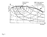
- the operation of the traction chain is stable because, for a control curve P of the electric traction as shown in Figure 2, even without knowing the real characteristics of the heat engine (these can change over time, in particular function of wear), at each throttle position, there is only one operating point on said piloting curve P.
- the piloting power curve P chosen has a single intersection with the power curve actually available P thd .
- the piloting curve P chosen joins the curve of real characteristics of the heat engine for a throttle opening of 100% at the maximum power speed of the heat engine.
- P t is the power used for traction of the vehicle and the term P a is an auxiliary power, not used for traction.
- P t is the power used for traction of the vehicle and the term P a is an auxiliary power, not used for traction.
- This modeling can be loaded into the central unit 30, and the measurement or knowledge of the various parameters such as the operating temperature of the various members, the rotation speeds, the electric currents, the setpoint torque C, make it possible to calculate a term P a (Annex power) at each iteration.
- thermodynamic efficiency of a conventional heat engine is not independent of its load, i.e. the throttle opening for a petrol engine.
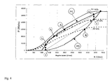
- the piloting curve PD of FIG. 4 is the same as the piloting curve P of FIG. 2. On this curve, we see that a power of 30,000 Watts is obtained at a speed of approximately 3750 rpm and a throttle position close to 60% opening (operating point "B"), while on the PE curve, we see that the same power of 30,000 Watts is obtained at a speed of around 2500 rpm and a throttle position close to 80% opening (operating point "A").
- the reaction of the global traction chain to an appropriate action on the control accelerator is slower than reacting to the same appropriate action on the control accelerator CA in the case where the programming of the unit 31 for controlling the torque of propulsion is based on the PD dynamic steering curve.
- the PP actuator is in a position much closer to the maximum throttle opening than in the second case.
- the acceleration reserve is much less in the case of piloting economical than in the case of dynamic steering. Therefore, in the case of piloting economical, the heat engine takes much longer to rev up and give higher power. Consequently, the torque setpoint C increases more slowly and the vehicle accelerates less strongly.
- the response to the accelerator is slow, a bit like on reports longest speeds with a conventional vehicle with a mechanical gearbox.
- the "Adjustment" parameter is chosen according to the characteristic curves of the operation of the thermal engine used.
- Adjustment dynamic a value of the "Adjustment” parameter of the order of 1.5
- Economic adjustment a value of the "Adjustment” parameter of the order of 0.7
- the limit modes being determined, it is very easy to automatically vary the “Adjustment” parameter as follows: the “Adjustment” parameter, from a value maximum “Dynamic adjustment” chosen to ensure dynamic steering, always tends towards the value "Economic adjustment", except in the event of an acceleration request by the driver.
- a low limit is introduced for the “Adjustment” parameter in order to give the vehicle great flexibility in maneuvering at low speed.
- the "Adjustment” parameter then changes between a high value called “Dynamic adjustment” and a low value called “Minimum adjustment”, with “Minimum adjustment” calculated as follows: where “v” is the instantaneous speed of the vehicle, capped at “Speed threshold”.
- the speed threshold is set between 15 and 30 km / h, for example at 20 km / h. Above speed threshold, management of the "Adjustment" parameter authorizes economic management.
- the driver may require full power during a long period. This is the case for example for an overshoot. It is therefore advantageous to be able program the propulsion torque control unit 31 to obtain the “kick down” effect well known for the automatic gearboxes of conventional vehicles.
- the driver manifests their desire by pushing the accelerator control CA, to the bottom race, and keeping it fully depressed as long as you want to have all the power.
- the throttle opening becomes maximum, within the limits explained above (saturation of the electric traction motor, traction control, ). And in this case, the parameter k keeps the value 1 as long as the driver keeps the accelerator pedal depressed. We stay at the point of operation with maximum opening of the PP actuator, as long as the pedal throttle remains depressed.
- the electric motors of traction in generators to provide an effect comparable to the engine brake of a vehicle conventional.
- the vehicle is then equipped with an electrical energy absorption device connected to said electrical line via a braking control unit 14.
- the control unit brake 14 automatically detects a transfer of energy going in the direction of recovery and directs it into the electrical energy absorption device. Since we are in braking, the operation of the torque control unit 31 has already caused the actuator to take PP an idle position (for more details, see the description in Figure 5 below).
- the invention having the particular feature that the control of the traction chain is designed to be able to operate without a buffer battery between the alternator 11 and the electric motors 21, the electric energy absorption device can be a simple electrical resistance 140 for dissipating braking energy. It is proposed that said threshold the accelerator control CA is proportional to the speed of the vehicle.
- the abscissa represents the accelerator control position CA available to the driver of the vehicle, and the ordinate represents the translation of this position into effective acceleration control CA e (positive or negative, and quantified).
- CA e positive or negative, and quantified.
- Positive acceleration requests allow the torque control unit 31 to determine a setpoint torque C as explained above. Acceleration requests negative allow the torque control unit 31 to control the absorption device 14, to send an "idle" setpoint to the PP actuator control device (unless other peripheral devices connected to line 12 require more energy electric than what the electric motors 21 provide in motor brake phase), and send a negative, more or less significant torque setpoint C to the inverters 22.
- the braking torque (as a reminder, the motors 21 are torque controlled) is therefore a function of the position of the accelerator pedal and instantaneous vehicle speed (see Figure 5).
- the setpoint torque C should be limited as a function of the maximum current admissible by the electric traction motor (s) 21 and as a function of the power maximum acceptable by dissipation resistance or energy absorbing device equivalent installed on the vehicle.
- the drive torque control unit calculates a setpoint torque C so as to maintain the speed of the vehicle at zero.
- the storage capacity is moderate (so as not to weigh down the vehicle), and the control device 32 tends to first drain the battery when requested acceleration of the vehicle indicated by the accelerator control CA, before acting on the PP actuator.
Landscapes
- Engineering & Computer Science (AREA)
- Chemical & Material Sciences (AREA)
- Combustion & Propulsion (AREA)
- Transportation (AREA)
- Mechanical Engineering (AREA)
- Sustainable Development (AREA)
- Life Sciences & Earth Sciences (AREA)
- Sustainable Energy (AREA)
- Power Engineering (AREA)
- Control Of Vehicle Engines Or Engines For Specific Uses (AREA)
- Hybrid Electric Vehicles (AREA)
- Electric Propulsion And Braking For Vehicles (AREA)
- Combined Controls Of Internal Combustion Engines (AREA)
Applications Claiming Priority (2)
| Application Number | Priority Date | Filing Date | Title |
|---|---|---|---|
| FR0103494 | 2001-03-14 | ||
| FR0103494 | 2001-03-14 |
Publications (1)
| Publication Number | Publication Date |
|---|---|
| EP1241043A1 true EP1241043A1 (fr) | 2002-09-18 |
Family
ID=8861135
Family Applications (1)
| Application Number | Title | Priority Date | Filing Date |
|---|---|---|---|
| EP02004997A Withdrawn EP1241043A1 (fr) | 2001-03-14 | 2002-03-06 | Véhicule hybride série capable de fonctionner sans batterie |
Country Status (4)
| Country | Link |
|---|---|
| US (1) | US6692403B2 (enExample) |
| EP (1) | EP1241043A1 (enExample) |
| JP (1) | JP3790964B2 (enExample) |
| CA (1) | CA2374801A1 (enExample) |
Cited By (4)
| Publication number | Priority date | Publication date | Assignee | Title |
|---|---|---|---|---|
| EP1428712A1 (fr) | 2002-12-11 | 2004-06-16 | Conception et Développement Michelin S.A. | Chaíne de traction et procedé de réglage pour véhicule hybride série |
| WO2013068808A1 (en) * | 2011-11-10 | 2013-05-16 | Toyota Jidosha Kabushiki Kaisha | Vehicle and vehicle control method |
| WO2013076566A1 (en) * | 2011-11-24 | 2013-05-30 | Toyota Jidosha Kabushiki Kaisha | Vehicle and control method for vehicle |
| EP3363670B1 (en) * | 2017-02-21 | 2022-03-30 | Iveco S.p.A. | Method and device for managing the propulsion of a parallel hybrid vehicle |
Families Citing this family (18)
| Publication number | Priority date | Publication date | Assignee | Title |
|---|---|---|---|---|
| JP4114788B2 (ja) * | 2003-03-13 | 2008-07-09 | 本田技研工業株式会社 | ハイブリッド方式の作業機 |
| JP3843966B2 (ja) * | 2003-06-05 | 2006-11-08 | アイシン・エィ・ダブリュ株式会社 | ハイブリッド型車両駆動制御装置、ハイブリッド型車両駆動制御方法及びそのプログラム |
| JP4097570B2 (ja) * | 2003-06-25 | 2008-06-11 | トヨタ自動車株式会社 | 車両用コネクタの配策構造 |
| JP4217192B2 (ja) * | 2004-06-01 | 2009-01-28 | 富士重工業株式会社 | ハイブリッド車両の制御装置 |
| WO2006039520A1 (en) * | 2004-09-30 | 2006-04-13 | Mtd Products Inc. | Hybrid utility vehicle |
| US7543454B2 (en) * | 2005-03-14 | 2009-06-09 | Zero Emission Systems, Inc. | Method and auxiliary system for operating a comfort subsystem for a vehicle |
| US7600595B2 (en) | 2005-03-14 | 2009-10-13 | Zero Emission Systems, Inc. | Electric traction |
| JP2006307797A (ja) * | 2005-05-02 | 2006-11-09 | Yamaha Motor Co Ltd | 鞍乗型車両のエンジン制御装置及びエンジン制御方法 |
| US7921945B2 (en) | 2006-02-21 | 2011-04-12 | Clean Emissions Technologies, Inc. | Vehicular switching, including switching traction modes and shifting gears while in electric traction mode |
| US8565969B2 (en) | 2007-04-03 | 2013-10-22 | Clean Emissions Technologies, Inc. | Over the road/traction/cabin comfort retrofit |
| US7921950B2 (en) * | 2006-11-10 | 2011-04-12 | Clean Emissions Technologies, Inc. | Electric traction retrofit |
| KR20110129980A (ko) | 2008-03-19 | 2011-12-02 | 클린 에미션스 테크놀로지스, 인코포레이티드 | 전기 견인 시스템 및 방법 |
| US9758146B2 (en) * | 2008-04-01 | 2017-09-12 | Clean Emissions Technologies, Inc. | Dual mode clutch pedal for vehicle |
| JP5307604B2 (ja) * | 2009-04-08 | 2013-10-02 | アイシン・エーアイ株式会社 | 車両の動力伝達制御装置 |
| US9631528B2 (en) | 2009-09-03 | 2017-04-25 | Clean Emissions Technologies, Inc. | Vehicle reduced emission deployment |
| DE102013013860A1 (de) * | 2013-08-20 | 2015-02-26 | Audi Ag | Fahrzeugantriebssteuerung |
| GB2555834A (en) * | 2016-11-11 | 2018-05-16 | Airbus Operations Ltd | Braking energy dissipation |
| IT201800002779A1 (it) * | 2018-02-16 | 2019-08-16 | Iveco Spa | Metodo e dispositivo di controllo della propulsione di un veicolo comprendente un motogeneratore elettrico di propulsione |
Citations (3)
| Publication number | Priority date | Publication date | Assignee | Title |
|---|---|---|---|---|
| US5935040A (en) * | 1996-07-23 | 1999-08-10 | Toyota Jidosha Kabushiki Kaisha | Hybrid vehicle drive system adapted to produce substantially constant vehicle drive force under the same vehicle running condition, even in different modes of operation |
| US5993351A (en) * | 1997-12-05 | 1999-11-30 | Nissan Motor Co., Ltd. | Control device for hybrid vehicle |
| US6155954A (en) * | 1998-09-22 | 2000-12-05 | Nissan Motor Co., Ltd. | Engine output control device for hybrid vehicle |
Family Cites Families (7)
| Publication number | Priority date | Publication date | Assignee | Title |
|---|---|---|---|---|
| US5762156A (en) * | 1995-10-31 | 1998-06-09 | Ford Global Technologies, Inc. | Hybrid electric propulsion system using a dual shaft turbine engine |
| US5761028A (en) * | 1996-05-02 | 1998-06-02 | Chrysler Corporation | Transistor connection assembly having IGBT (X) cross ties |
| DE50016077D1 (de) * | 1999-01-20 | 2011-04-28 | Voith Turbo Kg | Antriebssystem für Fahrzeuge, insbesondere für Nutzkraftwagen und elektrische Baueinheit |
| US6163121A (en) * | 1999-01-29 | 2000-12-19 | General Electric Company | Torque maximization and vibration control for AC locomotives |
| US6104148A (en) * | 1999-04-15 | 2000-08-15 | General Electric Company | System and method for controlling an AC traction motor without sensing motor rotation speed |
| US6484830B1 (en) * | 2000-04-26 | 2002-11-26 | Bowling Green State University | Hybrid electric vehicle |
| US6359346B1 (en) * | 2000-08-23 | 2002-03-19 | General Electric Company | Processor and method for accommodating failed speed sensors in a locomotive |
-
2002
- 2002-03-06 EP EP02004997A patent/EP1241043A1/fr not_active Withdrawn
- 2002-03-08 CA CA002374801A patent/CA2374801A1/fr not_active Abandoned
- 2002-03-13 US US10/097,021 patent/US6692403B2/en not_active Expired - Fee Related
- 2002-03-14 JP JP2002070646A patent/JP3790964B2/ja not_active Expired - Fee Related
Patent Citations (3)
| Publication number | Priority date | Publication date | Assignee | Title |
|---|---|---|---|---|
| US5935040A (en) * | 1996-07-23 | 1999-08-10 | Toyota Jidosha Kabushiki Kaisha | Hybrid vehicle drive system adapted to produce substantially constant vehicle drive force under the same vehicle running condition, even in different modes of operation |
| US5993351A (en) * | 1997-12-05 | 1999-11-30 | Nissan Motor Co., Ltd. | Control device for hybrid vehicle |
| US6155954A (en) * | 1998-09-22 | 2000-12-05 | Nissan Motor Co., Ltd. | Engine output control device for hybrid vehicle |
Cited By (9)
| Publication number | Priority date | Publication date | Assignee | Title |
|---|---|---|---|---|
| EP1428712A1 (fr) | 2002-12-11 | 2004-06-16 | Conception et Développement Michelin S.A. | Chaíne de traction et procedé de réglage pour véhicule hybride série |
| US7096098B2 (en) | 2002-12-11 | 2006-08-22 | Conception Et Developpement Michelin S.A. | Traction chain for a series hybrid vehicle |
| WO2013068808A1 (en) * | 2011-11-10 | 2013-05-16 | Toyota Jidosha Kabushiki Kaisha | Vehicle and vehicle control method |
| CN103917391A (zh) * | 2011-11-10 | 2014-07-09 | 丰田自动车株式会社 | 车辆和车辆控制方法 |
| CN103917391B (zh) * | 2011-11-10 | 2016-05-04 | 丰田自动车株式会社 | 车辆和车辆控制方法 |
| WO2013076566A1 (en) * | 2011-11-24 | 2013-05-30 | Toyota Jidosha Kabushiki Kaisha | Vehicle and control method for vehicle |
| CN103958243A (zh) * | 2011-11-24 | 2014-07-30 | 丰田自动车株式会社 | 车辆和用于车辆的控制方法 |
| CN103958243B (zh) * | 2011-11-24 | 2016-11-02 | 丰田自动车株式会社 | 车辆和用于车辆的控制方法 |
| EP3363670B1 (en) * | 2017-02-21 | 2022-03-30 | Iveco S.p.A. | Method and device for managing the propulsion of a parallel hybrid vehicle |
Also Published As
| Publication number | Publication date |
|---|---|
| US20020183161A1 (en) | 2002-12-05 |
| JP2002369312A (ja) | 2002-12-20 |
| JP3790964B2 (ja) | 2006-06-28 |
| CA2374801A1 (fr) | 2002-09-14 |
| US6692403B2 (en) | 2004-02-17 |
Similar Documents
| Publication | Publication Date | Title |
|---|---|---|
| EP1241043A1 (fr) | Véhicule hybride série capable de fonctionner sans batterie | |
| EP1428712B1 (fr) | Chaîne de traction et procedé de réglage pour véhicule hybride série | |
| FR2956637A1 (fr) | Procede de gestion d'un systeme d'entrainement pour vehicule automobile | |
| CH687307A5 (fr) | Ensemble de propulsion d'un véhicule. | |
| WO2006092522A1 (fr) | Procede de decollage rapide d'un vehicule hybride | |
| FR2973872A1 (fr) | Dispositif et procede de gestion d'un vehicule automobile | |
| FR2809352A1 (fr) | Groupe motopropulseur d'un vehicule hybride et son procede de commande | |
| EP1255175A1 (fr) | Procédé de synthése d'un loi de commande d'une transmission infiniment variable pour vehicule automobile. | |
| FR2990672A1 (fr) | Procede et dispositif pour la commande d'un moteur a combustion interne | |
| EP1224092A1 (fr) | Procede de commande d'un vehicule hybride | |
| EP3074257B1 (fr) | Procede et systeme de demarrage d'un moteur thermique | |
| WO2018109300A1 (fr) | Controle de vitesse d'un vehicule | |
| EP1072459A1 (fr) | Dispositif de commande du démarrage d'un véhicule automobile | |
| FR2742100A1 (fr) | Vehicule automobile a motorisation hybride | |
| FR2777231A1 (fr) | Procede d'assistance pour une faible vitesse du moteur thermique d'un vehicule hybride | |
| FR2954257A1 (fr) | Groupe motopropulseur hybride. | |
| EP1452383B1 (fr) | Système de régulation mécanique du dispositif de transmission de mouvement pour un véhicule automobile | |
| FR2528769A1 (fr) | Ensemble motopropulseur pourvu d'un volant a inertie pour vehicule a roues | |
| FR2801253A1 (fr) | Procede de recuperation d'energie sur un vehicule en deceleration | |
| FR2780350A1 (fr) | Vehicule automobile comportant un dispositif de regulation automatique de la vitesse | |
| EP0576945B1 (fr) | Système de propulsion pour un véhicule | |
| EP4222009A1 (fr) | Dispositif de contrôle de redémarrage d'un moteur a combustion d'un véhicule hybride | |
| FR2806672A1 (fr) | Procede de commande de differents composants d'un systeme de transmission d'un vehicule automobile | |
| FR2947222A1 (fr) | Procede de fonctionnement d'un vehicule hybride et dispositif de controle associe. | |
| FR2783768A1 (fr) | Procede de commande d'un vehicule hybride a transmission electrique serie |
Legal Events
| Date | Code | Title | Description |
|---|---|---|---|
| PUAI | Public reference made under article 153(3) epc to a published international application that has entered the european phase |
Free format text: ORIGINAL CODE: 0009012 |
|
| AK | Designated contracting states |
Kind code of ref document: A1 Designated state(s): AT BE CH CY DE DK ES FI FR GB GR IE IT LI LU MC NL PT SE TR |
|
| AX | Request for extension of the european patent |
Free format text: AL;LT;LV;MK;RO;SI |
|
| 17P | Request for examination filed |
Effective date: 20030318 |
|
| AKX | Designation fees paid |
Designated state(s): AT BE CH CY DE DK ES FI FR GB GR IE IT LI LU MC NL PT SE TR |
|
| 17Q | First examination report despatched |
Effective date: 20100218 |
|
| STAA | Information on the status of an ep patent application or granted ep patent |
Free format text: STATUS: THE APPLICATION HAS BEEN WITHDRAWN |
|
| 18W | Application withdrawn |
Effective date: 20100604 |