EP1241043A1 - Series hybrid vehicle, capable to drive without batteries - Google Patents
Series hybrid vehicle, capable to drive without batteries Download PDFInfo
- Publication number
- EP1241043A1 EP1241043A1 EP02004997A EP02004997A EP1241043A1 EP 1241043 A1 EP1241043 A1 EP 1241043A1 EP 02004997 A EP02004997 A EP 02004997A EP 02004997 A EP02004997 A EP 02004997A EP 1241043 A1 EP1241043 A1 EP 1241043A1
- Authority
- EP
- European Patent Office
- Prior art keywords
- speed
- vehicle
- torque
- power
- control
- Prior art date
- Legal status (The legal status is an assumption and is not a legal conclusion. Google has not performed a legal analysis and makes no representation as to the accuracy of the status listed.)
- Withdrawn
Links
- 238000004364 calculation method Methods 0.000 claims abstract description 8
- 230000001133 acceleration Effects 0.000 claims description 21
- 230000009471 action Effects 0.000 claims description 7
- 238000012546 transfer Methods 0.000 claims description 3
- 230000037213 diet Effects 0.000 claims description 2
- 235000005911 diet Nutrition 0.000 claims description 2
- 238000000034 method Methods 0.000 claims description 2
- 238000005070 sampling Methods 0.000 claims description 2
- 230000033228 biological regulation Effects 0.000 abstract description 4
- 230000001276 controlling effect Effects 0.000 description 8
- 210000000056 organ Anatomy 0.000 description 7
- 230000002093 peripheral effect Effects 0.000 description 7
- 238000010521 absorption reaction Methods 0.000 description 6
- 238000010586 diagram Methods 0.000 description 5
- XDDAORKBJWWYJS-UHFFFAOYSA-N glyphosate Chemical group OC(=O)CNCP(O)(O)=O XDDAORKBJWWYJS-UHFFFAOYSA-N 0.000 description 5
- 238000002485 combustion reaction Methods 0.000 description 4
- 239000000446 fuel Substances 0.000 description 4
- 230000007935 neutral effect Effects 0.000 description 4
- 230000004044 response Effects 0.000 description 4
- 230000000994 depressogenic effect Effects 0.000 description 3
- 230000000694 effects Effects 0.000 description 3
- 238000011156 evaluation Methods 0.000 description 3
- XEEYBQQBJWHFJM-UHFFFAOYSA-N Iron Chemical compound [Fe] XEEYBQQBJWHFJM-UHFFFAOYSA-N 0.000 description 2
- 230000008859 change Effects 0.000 description 2
- 238000006243 chemical reaction Methods 0.000 description 2
- 230000007423 decrease Effects 0.000 description 2
- 238000005259 measurement Methods 0.000 description 2
- 238000012545 processing Methods 0.000 description 2
- 230000004043 responsiveness Effects 0.000 description 2
- 230000001360 synchronised effect Effects 0.000 description 2
- 230000006978 adaptation Effects 0.000 description 1
- 238000013459 approach Methods 0.000 description 1
- 230000008901 benefit Effects 0.000 description 1
- 238000012937 correction Methods 0.000 description 1
- 230000001186 cumulative effect Effects 0.000 description 1
- 230000006378 damage Effects 0.000 description 1
- 238000013461 design Methods 0.000 description 1
- 238000005265 energy consumption Methods 0.000 description 1
- 238000002474 experimental method Methods 0.000 description 1
- 230000002349 favourable effect Effects 0.000 description 1
- 230000004907 flux Effects 0.000 description 1
- 238000002347 injection Methods 0.000 description 1
- 239000007924 injection Substances 0.000 description 1
- 229910052742 iron Inorganic materials 0.000 description 1
- 238000012423 maintenance Methods 0.000 description 1
- 239000000463 material Substances 0.000 description 1
- 238000013021 overheating Methods 0.000 description 1
- 230000000750 progressive effect Effects 0.000 description 1
- 230000009257 reactivity Effects 0.000 description 1
- 238000011084 recovery Methods 0.000 description 1
- 230000001105 regulatory effect Effects 0.000 description 1
- 238000013519 translation Methods 0.000 description 1
- 239000011800 void material Substances 0.000 description 1
- 239000002699 waste material Substances 0.000 description 1
Images


Classifications
-
- B—PERFORMING OPERATIONS; TRANSPORTING
- B60—VEHICLES IN GENERAL
- B60W—CONJOINT CONTROL OF VEHICLE SUB-UNITS OF DIFFERENT TYPE OR DIFFERENT FUNCTION; CONTROL SYSTEMS SPECIALLY ADAPTED FOR HYBRID VEHICLES; ROAD VEHICLE DRIVE CONTROL SYSTEMS FOR PURPOSES NOT RELATED TO THE CONTROL OF A PARTICULAR SUB-UNIT
- B60W10/00—Conjoint control of vehicle sub-units of different type or different function
- B60W10/04—Conjoint control of vehicle sub-units of different type or different function including control of propulsion units
- B60W10/08—Conjoint control of vehicle sub-units of different type or different function including control of propulsion units including control of electric propulsion units, e.g. motors or generators
-
- B—PERFORMING OPERATIONS; TRANSPORTING
- B60—VEHICLES IN GENERAL
- B60K—ARRANGEMENT OR MOUNTING OF PROPULSION UNITS OR OF TRANSMISSIONS IN VEHICLES; ARRANGEMENT OR MOUNTING OF PLURAL DIVERSE PRIME-MOVERS IN VEHICLES; AUXILIARY DRIVES FOR VEHICLES; INSTRUMENTATION OR DASHBOARDS FOR VEHICLES; ARRANGEMENTS IN CONNECTION WITH COOLING, AIR INTAKE, GAS EXHAUST OR FUEL SUPPLY OF PROPULSION UNITS IN VEHICLES
- B60K6/00—Arrangement or mounting of plural diverse prime-movers for mutual or common propulsion, e.g. hybrid propulsion systems comprising electric motors and internal combustion engines ; Control systems therefor, i.e. systems controlling two or more prime movers, or controlling one of these prime movers and any of the transmission, drive or drive units Informative references: mechanical gearings with secondary electric drive F16H3/72; arrangements for handling mechanical energy structurally associated with the dynamo-electric machine H02K7/00; machines comprising structurally interrelated motor and generator parts H02K51/00; dynamo-electric machines not otherwise provided for in H02K see H02K99/00
- B60K6/20—Arrangement or mounting of plural diverse prime-movers for mutual or common propulsion, e.g. hybrid propulsion systems comprising electric motors and internal combustion engines ; Control systems therefor, i.e. systems controlling two or more prime movers, or controlling one of these prime movers and any of the transmission, drive or drive units Informative references: mechanical gearings with secondary electric drive F16H3/72; arrangements for handling mechanical energy structurally associated with the dynamo-electric machine H02K7/00; machines comprising structurally interrelated motor and generator parts H02K51/00; dynamo-electric machines not otherwise provided for in H02K see H02K99/00 the prime-movers consisting of electric motors and internal combustion engines, e.g. HEVs
- B60K6/22—Arrangement or mounting of plural diverse prime-movers for mutual or common propulsion, e.g. hybrid propulsion systems comprising electric motors and internal combustion engines ; Control systems therefor, i.e. systems controlling two or more prime movers, or controlling one of these prime movers and any of the transmission, drive or drive units Informative references: mechanical gearings with secondary electric drive F16H3/72; arrangements for handling mechanical energy structurally associated with the dynamo-electric machine H02K7/00; machines comprising structurally interrelated motor and generator parts H02K51/00; dynamo-electric machines not otherwise provided for in H02K see H02K99/00 the prime-movers consisting of electric motors and internal combustion engines, e.g. HEVs characterised by apparatus, components or means specially adapted for HEVs
- B60K6/34—Arrangement or mounting of plural diverse prime-movers for mutual or common propulsion, e.g. hybrid propulsion systems comprising electric motors and internal combustion engines ; Control systems therefor, i.e. systems controlling two or more prime movers, or controlling one of these prime movers and any of the transmission, drive or drive units Informative references: mechanical gearings with secondary electric drive F16H3/72; arrangements for handling mechanical energy structurally associated with the dynamo-electric machine H02K7/00; machines comprising structurally interrelated motor and generator parts H02K51/00; dynamo-electric machines not otherwise provided for in H02K see H02K99/00 the prime-movers consisting of electric motors and internal combustion engines, e.g. HEVs characterised by apparatus, components or means specially adapted for HEVs characterised by the absence of energy storing means
-
- B—PERFORMING OPERATIONS; TRANSPORTING
- B60—VEHICLES IN GENERAL
- B60K—ARRANGEMENT OR MOUNTING OF PROPULSION UNITS OR OF TRANSMISSIONS IN VEHICLES; ARRANGEMENT OR MOUNTING OF PLURAL DIVERSE PRIME-MOVERS IN VEHICLES; AUXILIARY DRIVES FOR VEHICLES; INSTRUMENTATION OR DASHBOARDS FOR VEHICLES; ARRANGEMENTS IN CONNECTION WITH COOLING, AIR INTAKE, GAS EXHAUST OR FUEL SUPPLY OF PROPULSION UNITS IN VEHICLES
- B60K6/00—Arrangement or mounting of plural diverse prime-movers for mutual or common propulsion, e.g. hybrid propulsion systems comprising electric motors and internal combustion engines ; Control systems therefor, i.e. systems controlling two or more prime movers, or controlling one of these prime movers and any of the transmission, drive or drive units Informative references: mechanical gearings with secondary electric drive F16H3/72; arrangements for handling mechanical energy structurally associated with the dynamo-electric machine H02K7/00; machines comprising structurally interrelated motor and generator parts H02K51/00; dynamo-electric machines not otherwise provided for in H02K see H02K99/00
- B60K6/20—Arrangement or mounting of plural diverse prime-movers for mutual or common propulsion, e.g. hybrid propulsion systems comprising electric motors and internal combustion engines ; Control systems therefor, i.e. systems controlling two or more prime movers, or controlling one of these prime movers and any of the transmission, drive or drive units Informative references: mechanical gearings with secondary electric drive F16H3/72; arrangements for handling mechanical energy structurally associated with the dynamo-electric machine H02K7/00; machines comprising structurally interrelated motor and generator parts H02K51/00; dynamo-electric machines not otherwise provided for in H02K see H02K99/00 the prime-movers consisting of electric motors and internal combustion engines, e.g. HEVs
- B60K6/42—Arrangement or mounting of plural diverse prime-movers for mutual or common propulsion, e.g. hybrid propulsion systems comprising electric motors and internal combustion engines ; Control systems therefor, i.e. systems controlling two or more prime movers, or controlling one of these prime movers and any of the transmission, drive or drive units Informative references: mechanical gearings with secondary electric drive F16H3/72; arrangements for handling mechanical energy structurally associated with the dynamo-electric machine H02K7/00; machines comprising structurally interrelated motor and generator parts H02K51/00; dynamo-electric machines not otherwise provided for in H02K see H02K99/00 the prime-movers consisting of electric motors and internal combustion engines, e.g. HEVs characterised by the architecture of the hybrid electric vehicle
- B60K6/46—Series type
-
- B—PERFORMING OPERATIONS; TRANSPORTING
- B60—VEHICLES IN GENERAL
- B60L—PROPULSION OF ELECTRICALLY-PROPELLED VEHICLES; SUPPLYING ELECTRIC POWER FOR AUXILIARY EQUIPMENT OF ELECTRICALLY-PROPELLED VEHICLES; ELECTRODYNAMIC BRAKE SYSTEMS FOR VEHICLES IN GENERAL; MAGNETIC SUSPENSION OR LEVITATION FOR VEHICLES; MONITORING OPERATING VARIABLES OF ELECTRICALLY-PROPELLED VEHICLES; ELECTRIC SAFETY DEVICES FOR ELECTRICALLY-PROPELLED VEHICLES
- B60L50/00—Electric propulsion with power supplied within the vehicle
- B60L50/50—Electric propulsion with power supplied within the vehicle using propulsion power supplied by batteries or fuel cells
- B60L50/60—Electric propulsion with power supplied within the vehicle using propulsion power supplied by batteries or fuel cells using power supplied by batteries
- B60L50/61—Electric propulsion with power supplied within the vehicle using propulsion power supplied by batteries or fuel cells using power supplied by batteries by batteries charged by engine-driven generators, e.g. series hybrid electric vehicles
-
- B—PERFORMING OPERATIONS; TRANSPORTING
- B60—VEHICLES IN GENERAL
- B60L—PROPULSION OF ELECTRICALLY-PROPELLED VEHICLES; SUPPLYING ELECTRIC POWER FOR AUXILIARY EQUIPMENT OF ELECTRICALLY-PROPELLED VEHICLES; ELECTRODYNAMIC BRAKE SYSTEMS FOR VEHICLES IN GENERAL; MAGNETIC SUSPENSION OR LEVITATION FOR VEHICLES; MONITORING OPERATING VARIABLES OF ELECTRICALLY-PROPELLED VEHICLES; ELECTRIC SAFETY DEVICES FOR ELECTRICALLY-PROPELLED VEHICLES
- B60L2240/00—Control parameters of input or output; Target parameters
- B60L2240/40—Drive Train control parameters
- B60L2240/44—Drive Train control parameters related to combustion engines
- B60L2240/441—Speed
-
- B—PERFORMING OPERATIONS; TRANSPORTING
- B60—VEHICLES IN GENERAL
- B60L—PROPULSION OF ELECTRICALLY-PROPELLED VEHICLES; SUPPLYING ELECTRIC POWER FOR AUXILIARY EQUIPMENT OF ELECTRICALLY-PROPELLED VEHICLES; ELECTRODYNAMIC BRAKE SYSTEMS FOR VEHICLES IN GENERAL; MAGNETIC SUSPENSION OR LEVITATION FOR VEHICLES; MONITORING OPERATING VARIABLES OF ELECTRICALLY-PROPELLED VEHICLES; ELECTRIC SAFETY DEVICES FOR ELECTRICALLY-PROPELLED VEHICLES
- B60L2240/00—Control parameters of input or output; Target parameters
- B60L2240/40—Drive Train control parameters
- B60L2240/48—Drive Train control parameters related to transmissions
- B60L2240/486—Operating parameters
-
- B—PERFORMING OPERATIONS; TRANSPORTING
- B60—VEHICLES IN GENERAL
- B60W—CONJOINT CONTROL OF VEHICLE SUB-UNITS OF DIFFERENT TYPE OR DIFFERENT FUNCTION; CONTROL SYSTEMS SPECIALLY ADAPTED FOR HYBRID VEHICLES; ROAD VEHICLE DRIVE CONTROL SYSTEMS FOR PURPOSES NOT RELATED TO THE CONTROL OF A PARTICULAR SUB-UNIT
- B60W2510/00—Input parameters relating to a particular sub-units
- B60W2510/06—Combustion engines, Gas turbines
- B60W2510/0638—Engine speed
-
- B—PERFORMING OPERATIONS; TRANSPORTING
- B60—VEHICLES IN GENERAL
- B60W—CONJOINT CONTROL OF VEHICLE SUB-UNITS OF DIFFERENT TYPE OR DIFFERENT FUNCTION; CONTROL SYSTEMS SPECIALLY ADAPTED FOR HYBRID VEHICLES; ROAD VEHICLE DRIVE CONTROL SYSTEMS FOR PURPOSES NOT RELATED TO THE CONTROL OF A PARTICULAR SUB-UNIT
- B60W2540/00—Input parameters relating to occupants
- B60W2540/10—Accelerator pedal position
-
- B—PERFORMING OPERATIONS; TRANSPORTING
- B60—VEHICLES IN GENERAL
- B60W—CONJOINT CONTROL OF VEHICLE SUB-UNITS OF DIFFERENT TYPE OR DIFFERENT FUNCTION; CONTROL SYSTEMS SPECIALLY ADAPTED FOR HYBRID VEHICLES; ROAD VEHICLE DRIVE CONTROL SYSTEMS FOR PURPOSES NOT RELATED TO THE CONTROL OF A PARTICULAR SUB-UNIT
- B60W2710/00—Output or target parameters relating to a particular sub-units
- B60W2710/06—Combustion engines, Gas turbines
- B60W2710/0644—Engine speed
- B60W2710/065—Idle condition
-
- B—PERFORMING OPERATIONS; TRANSPORTING
- B60—VEHICLES IN GENERAL
- B60W—CONJOINT CONTROL OF VEHICLE SUB-UNITS OF DIFFERENT TYPE OR DIFFERENT FUNCTION; CONTROL SYSTEMS SPECIALLY ADAPTED FOR HYBRID VEHICLES; ROAD VEHICLE DRIVE CONTROL SYSTEMS FOR PURPOSES NOT RELATED TO THE CONTROL OF A PARTICULAR SUB-UNIT
- B60W2710/00—Output or target parameters relating to a particular sub-units
- B60W2710/10—Change speed gearings
- B60W2710/105—Output torque
-
- Y—GENERAL TAGGING OF NEW TECHNOLOGICAL DEVELOPMENTS; GENERAL TAGGING OF CROSS-SECTIONAL TECHNOLOGIES SPANNING OVER SEVERAL SECTIONS OF THE IPC; TECHNICAL SUBJECTS COVERED BY FORMER USPC CROSS-REFERENCE ART COLLECTIONS [XRACs] AND DIGESTS
- Y02—TECHNOLOGIES OR APPLICATIONS FOR MITIGATION OR ADAPTATION AGAINST CLIMATE CHANGE
- Y02T—CLIMATE CHANGE MITIGATION TECHNOLOGIES RELATED TO TRANSPORTATION
- Y02T10/00—Road transport of goods or passengers
- Y02T10/60—Other road transportation technologies with climate change mitigation effect
- Y02T10/62—Hybrid vehicles
-
- Y—GENERAL TAGGING OF NEW TECHNOLOGICAL DEVELOPMENTS; GENERAL TAGGING OF CROSS-SECTIONAL TECHNOLOGIES SPANNING OVER SEVERAL SECTIONS OF THE IPC; TECHNICAL SUBJECTS COVERED BY FORMER USPC CROSS-REFERENCE ART COLLECTIONS [XRACs] AND DIGESTS
- Y02—TECHNOLOGIES OR APPLICATIONS FOR MITIGATION OR ADAPTATION AGAINST CLIMATE CHANGE
- Y02T—CLIMATE CHANGE MITIGATION TECHNOLOGIES RELATED TO TRANSPORTATION
- Y02T10/00—Road transport of goods or passengers
- Y02T10/60—Other road transportation technologies with climate change mitigation effect
- Y02T10/70—Energy storage systems for electromobility, e.g. batteries
-
- Y—GENERAL TAGGING OF NEW TECHNOLOGICAL DEVELOPMENTS; GENERAL TAGGING OF CROSS-SECTIONAL TECHNOLOGIES SPANNING OVER SEVERAL SECTIONS OF THE IPC; TECHNICAL SUBJECTS COVERED BY FORMER USPC CROSS-REFERENCE ART COLLECTIONS [XRACs] AND DIGESTS
- Y02—TECHNOLOGIES OR APPLICATIONS FOR MITIGATION OR ADAPTATION AGAINST CLIMATE CHANGE
- Y02T—CLIMATE CHANGE MITIGATION TECHNOLOGIES RELATED TO TRANSPORTATION
- Y02T10/00—Road transport of goods or passengers
- Y02T10/60—Other road transportation technologies with climate change mitigation effect
- Y02T10/7072—Electromobility specific charging systems or methods for batteries, ultracapacitors, supercapacitors or double-layer capacitors
-
- Y—GENERAL TAGGING OF NEW TECHNOLOGICAL DEVELOPMENTS; GENERAL TAGGING OF CROSS-SECTIONAL TECHNOLOGIES SPANNING OVER SEVERAL SECTIONS OF THE IPC; TECHNICAL SUBJECTS COVERED BY FORMER USPC CROSS-REFERENCE ART COLLECTIONS [XRACs] AND DIGESTS
- Y02—TECHNOLOGIES OR APPLICATIONS FOR MITIGATION OR ADAPTATION AGAINST CLIMATE CHANGE
- Y02T—CLIMATE CHANGE MITIGATION TECHNOLOGIES RELATED TO TRANSPORTATION
- Y02T10/00—Road transport of goods or passengers
- Y02T10/60—Other road transportation technologies with climate change mitigation effect
- Y02T10/72—Electric energy management in electromobility
Definitions
- the present invention relates to road motor vehicles, with series hybrid motorization.
- a heat engine drives an electric alternator which transforms the mechanical energy available at the engine shaft into electrical energy.
- This electrical energy powers one or more electric traction motors, connected mechanically to the drive wheels of the vehicle.
- the heat engine is not connected mechanically at the wheels, unlike parallel hybrid vehicles, in both a heat engine and an electric motor are mechanically connected to the drive wheels, the torques they deliver can add up to drive the wheels drive.
- the purpose of the present invention is therefore to design a series hybrid powertrain which can optionally operate without an electric storage battery, while providing the driver of the vehicle a very progressive and very responsive throttle control.
- a series hybrid powertrain which can optionally operate without an electric storage battery, while providing the driver of the vehicle a very progressive and very responsive throttle control.
- the problem is therefore to obtain the desired torque from the electric traction motor while avoiding stalling or the runaway of the engine, and this by means of a control whose progressiveness and responsiveness are as close as possible to that of a vehicle accelerator pedal conventional thermal.
- the heat engine is of any type that can be controlled by a command variable like an accelerator pedal.
- a command variable like an accelerator pedal.
- diesel engines in which the control acts on the quantity of fuel injected into the combustion chamber.
- petrol engines in which the control acts on the amount of air admitted into the combustion chamber.
- the electric traction motor there may be only one, or several, for example one per vehicle wheel. If there are several electric traction motors, it should be understood by "Setpoint torque C" a cumulative overall torque for all the motors, the present invention not concerning the question of the distribution of the torque between the motors.
- the type of electric motor this is a motor whose torque delivered to the shaft can be controlled rotation, amplitude and sign. It is, for example, a self-controlled synchronous machine, flux concentration, inductor with permanent magnets.
- the alternator used is for example an electrical machine of the same type as that proposed. for the electric traction motor.
- the alternator transforms the mechanical energy available to the output shaft of the heat engine into electrical energy consumed by the electrical load connected to the power line on which said alternator outputs (for this presentation, the load electric is mainly the electric traction motor (s).
- the piloting power P proceeds from an evaluation of the power of the available heat engine P thd .
- Said pilot power P is not the exact image of the power actually available P thd to the shaft of the heat engine.
- Various control power curves will be given below as a function of the real speed R, curves which are superimposed on the real curves of available power P thd for different positions of the actuator PP. Since the piloting power P proceeds from an approximation more or less close to reality, the operating point of the heat engine giving a particular power as a function of the real engine speed R does not necessarily correspond to a balance between the power actually available P thd and the power consumed in electrical form by the loads connected to the alternator.
- the setpoint torque C is calculated by successive iterations.
- the accelerator control CA to arrangement of the driver does not act directly on the setpoint torque C of the motor electric traction. It acts on the heat engine.
- the setpoint torque C of the motor electric traction is automatically adapted to the actual operation of the heat engine.
- the accelerator control CA acts directly on the actuator PP.
- Said PP actuator also takes into account the torque absorbed by the electric traction motor because it is necessarily limited, under penalty of destruction of the electric motor in the event of excessive current intense. Indeed, at low vehicle travel speed, saturation is reached (current permissible by the electric motor and the inverter) for low power levels.
- the acceleration request should be clipped from the driver. It is only below the saturation of the electric motor that we can link, for example proportionally, the control of the PP actuator to the control AC accelerator on which the driver acts directly.
- FIG. 1 we see a petrol petrol engine 10, and an actuator 15 controlling the position of a throttle valve in an air intake manifold.
- the heat engine drives a alternator 11.
- the electrical energy supplied by the latter is distributed to four motors traction motors 21, via a rectifier 13, an electric line 12, and an inverter 22 by motor 21.
- An electrical energy absorption device 14 is connected to the line electric 12.
- a central unit 30 manages various functions, among which the electric traction chain of the vehicle (engine or brake torque of electric motors 21).
- Central unit 30 includes a control unit 31 of the propulsion torque of the electric motors 21 and a electronic device 32 for controlling the actuator 15 acting on the position of the butterfly PP, which acts on the power developed by the heat engine 10.
- the control unit 31 of the vehicle propulsion torque calculates said setpoint torque according to a period sampling method.
- the central processing unit 30 receives evaluation signals from different parameters like a potentiometer 40 reflecting the position of an AC accelerator control (a pedal or other equivalent control available to the driver of the vehicle), such as sensor 41 reflecting the position of the throttle valve PP, a sensor 42 giving the speed v of the vehicle, a sensor 43 giving the engine speed R, various temperature sensors 44, one sensor 45 giving the pressure of the vehicle's hydraulic braking circuit, the list being no comprehensive.
- a potentiometer 40 reflecting the position of an AC accelerator control (a pedal or other equivalent control available to the driver of the vehicle)
- sensor 41 reflecting the position of the throttle valve PP
- sensor 42 giving the speed v of the vehicle
- a sensor 43 giving the engine speed R
- various temperature sensors 44 one sensor 45 giving the pressure of the vehicle's hydraulic braking circuit
- peripheral organs absorb the power delivered by the thermal motor.
- the thermal motor With regard to the present invention, it does not matter that they take a mechanical power directly to the crankshaft of the heat engine or that they take a electrical power on power line 12 because this amounts to taking said power at crankshaft via the alternator.
- some of these peripheral organs can also be managed by the central unit 30, which has the advantage of being able to take into account variations in power consumed in the control device 32 of the actuator 15 even before the engine speed could have been changed.
- the electric traction motors 21 are three-phase synchronous motors, equipped with a angular position sensor of the resolver type and are controlled by the inverters 22, under the control of the propulsion torque control unit 31.
- the electronics are designed for drive the motors in torque. Therefore the traction set can be used as an engine and brake.
- the actuator 15 consists essentially of a small direct current electric motor, coupled to the throttle valve of the heat engine.
- This engine is managed by electronics and, thanks to a position sensor 41 (potentiometer), the throttle is permanently controlled by position.
- the throttle position generated obviously depends on the torque desired for the engine electric traction (torque which can be negative), and is also adapted according to a possible excessive consumption by peripheral organs.
- a CAN® 50 bus (Controller Area Network) interconnects the various components. This allows the central unit 30, chosen as master of the network, to receive in particular the speed of the wheel driven by the electric motor 21 and a diagnostic on operation in from the inverters 22, and send a setpoint torque C to the inverters 22.
- the sensor 40 giving the position of the accelerator pedal delivers a signal which allows the 3 following functions: normal acceleration, maximum possible acceleration (comparable to so-called “kick-down” position in classic vehicles with automatic gearbox), and Engine brake.
- the engine brake operation is left aside for the moment.
- the control device 32 orders the actuator 15 to open the air butterfly.
- the butterfly is set to 60% opening following the action of the driver on the accelerator, at the initial speed of 3100 rpm, the engine actually provides 27000 Watts (operating point 2 ⁇ ).
- the electrical power consumed since traction has not changed the electric power consumed by traction is less than the power supplied by the engine.
- the engine speed 10 goes therefore increase.
- the setpoint calculated for the torque C increases automatically, as determined by the control curve P of the electric traction.
- the motor can only supply 21000 Watts (operating point 4 ⁇ ).
- the electrical power consumed by traction having remained greater than the power supplied by the combustion engine, the latter will lose revolutions and stabilize at a speed of 3100 rpm (operating point 1 ⁇ , at the intersection of the piloting curve P and the curve real characteristic of the heat engine for a throttle opening at 40%), speed at which the electric power consumed by traction is equal to the power supplied by the motor thermal, i.e. 18000 Watts.
- the operation of the traction chain is stable because, for a control curve P of the electric traction as shown in Figure 2, even without knowing the real characteristics of the heat engine (these can change over time, in particular function of wear), at each throttle position, there is only one operating point on said piloting curve P.
- the piloting power curve P chosen has a single intersection with the power curve actually available P thd .
- the piloting curve P chosen joins the curve of real characteristics of the heat engine for a throttle opening of 100% at the maximum power speed of the heat engine.
- P t is the power used for traction of the vehicle and the term P a is an auxiliary power, not used for traction.
- P t is the power used for traction of the vehicle and the term P a is an auxiliary power, not used for traction.
- This modeling can be loaded into the central unit 30, and the measurement or knowledge of the various parameters such as the operating temperature of the various members, the rotation speeds, the electric currents, the setpoint torque C, make it possible to calculate a term P a (Annex power) at each iteration.
- thermodynamic efficiency of a conventional heat engine is not independent of its load, i.e. the throttle opening for a petrol engine.
- the piloting curve PD of FIG. 4 is the same as the piloting curve P of FIG. 2. On this curve, we see that a power of 30,000 Watts is obtained at a speed of approximately 3750 rpm and a throttle position close to 60% opening (operating point "B"), while on the PE curve, we see that the same power of 30,000 Watts is obtained at a speed of around 2500 rpm and a throttle position close to 80% opening (operating point "A").
- the reaction of the global traction chain to an appropriate action on the control accelerator is slower than reacting to the same appropriate action on the control accelerator CA in the case where the programming of the unit 31 for controlling the torque of propulsion is based on the PD dynamic steering curve.
- the PP actuator is in a position much closer to the maximum throttle opening than in the second case.
- the acceleration reserve is much less in the case of piloting economical than in the case of dynamic steering. Therefore, in the case of piloting economical, the heat engine takes much longer to rev up and give higher power. Consequently, the torque setpoint C increases more slowly and the vehicle accelerates less strongly.
- the response to the accelerator is slow, a bit like on reports longest speeds with a conventional vehicle with a mechanical gearbox.
- the "Adjustment" parameter is chosen according to the characteristic curves of the operation of the thermal engine used.
- Adjustment dynamic a value of the "Adjustment” parameter of the order of 1.5
- Economic adjustment a value of the "Adjustment” parameter of the order of 0.7
- the limit modes being determined, it is very easy to automatically vary the “Adjustment” parameter as follows: the “Adjustment” parameter, from a value maximum “Dynamic adjustment” chosen to ensure dynamic steering, always tends towards the value "Economic adjustment", except in the event of an acceleration request by the driver.
- a low limit is introduced for the “Adjustment” parameter in order to give the vehicle great flexibility in maneuvering at low speed.
- the "Adjustment” parameter then changes between a high value called “Dynamic adjustment” and a low value called “Minimum adjustment”, with “Minimum adjustment” calculated as follows: where “v” is the instantaneous speed of the vehicle, capped at “Speed threshold”.
- the speed threshold is set between 15 and 30 km / h, for example at 20 km / h. Above speed threshold, management of the "Adjustment" parameter authorizes economic management.
- the driver may require full power during a long period. This is the case for example for an overshoot. It is therefore advantageous to be able program the propulsion torque control unit 31 to obtain the “kick down” effect well known for the automatic gearboxes of conventional vehicles.
- the driver manifests their desire by pushing the accelerator control CA, to the bottom race, and keeping it fully depressed as long as you want to have all the power.
- the throttle opening becomes maximum, within the limits explained above (saturation of the electric traction motor, traction control, ). And in this case, the parameter k keeps the value 1 as long as the driver keeps the accelerator pedal depressed. We stay at the point of operation with maximum opening of the PP actuator, as long as the pedal throttle remains depressed.
- the electric motors of traction in generators to provide an effect comparable to the engine brake of a vehicle conventional.
- the vehicle is then equipped with an electrical energy absorption device connected to said electrical line via a braking control unit 14.
- the control unit brake 14 automatically detects a transfer of energy going in the direction of recovery and directs it into the electrical energy absorption device. Since we are in braking, the operation of the torque control unit 31 has already caused the actuator to take PP an idle position (for more details, see the description in Figure 5 below).
- the invention having the particular feature that the control of the traction chain is designed to be able to operate without a buffer battery between the alternator 11 and the electric motors 21, the electric energy absorption device can be a simple electrical resistance 140 for dissipating braking energy. It is proposed that said threshold the accelerator control CA is proportional to the speed of the vehicle.
- the abscissa represents the accelerator control position CA available to the driver of the vehicle, and the ordinate represents the translation of this position into effective acceleration control CA e (positive or negative, and quantified).
- CA e positive or negative, and quantified.
- Positive acceleration requests allow the torque control unit 31 to determine a setpoint torque C as explained above. Acceleration requests negative allow the torque control unit 31 to control the absorption device 14, to send an "idle" setpoint to the PP actuator control device (unless other peripheral devices connected to line 12 require more energy electric than what the electric motors 21 provide in motor brake phase), and send a negative, more or less significant torque setpoint C to the inverters 22.
- the braking torque (as a reminder, the motors 21 are torque controlled) is therefore a function of the position of the accelerator pedal and instantaneous vehicle speed (see Figure 5).
- the setpoint torque C should be limited as a function of the maximum current admissible by the electric traction motor (s) 21 and as a function of the power maximum acceptable by dissipation resistance or energy absorbing device equivalent installed on the vehicle.
- the drive torque control unit calculates a setpoint torque C so as to maintain the speed of the vehicle at zero.
- the storage capacity is moderate (so as not to weigh down the vehicle), and the control device 32 tends to first drain the battery when requested acceleration of the vehicle indicated by the accelerator control CA, before acting on the PP actuator.
Landscapes
- Engineering & Computer Science (AREA)
- Chemical & Material Sciences (AREA)
- Combustion & Propulsion (AREA)
- Transportation (AREA)
- Mechanical Engineering (AREA)
- Sustainable Development (AREA)
- Life Sciences & Earth Sciences (AREA)
- Sustainable Energy (AREA)
- Power Engineering (AREA)
- Control Of Vehicle Engines Or Engines For Specific Uses (AREA)
- Hybrid Electric Vehicles (AREA)
- Electric Propulsion And Braking For Vehicles (AREA)
- Combined Controls Of Internal Combustion Engines (AREA)
Abstract
Description
La présente invention concerne les véhicules automobiles routiers, à motorisation hybride série. Dans les véhicules de ce type, un moteur thermique entraíne un alternateur électrique qui transforme l'énergie mécanique disponible à l'arbre du moteur thermique en énergie électrique. Cette énergie électrique alimente un ou des moteurs électriques de traction, reliés mécaniquement aux roues motrices du véhicule. Le moteur thermique n'est pas relié mécaniquement aux roues, contrairement aux véhicules à motorisation hybride parallèle, dans lesquels un moteur thermique et un moteur électrique sont tous les deux reliés mécaniquement aux roues motrices, les couples qu'ils délivrent pouvant s'additionner pour entraíner les roues motrices.The present invention relates to road motor vehicles, with series hybrid motorization. In vehicles of this type, a heat engine drives an electric alternator which transforms the mechanical energy available at the engine shaft into electrical energy. This electrical energy powers one or more electric traction motors, connected mechanically to the drive wheels of the vehicle. The heat engine is not connected mechanically at the wheels, unlike parallel hybrid vehicles, in both a heat engine and an electric motor are mechanically connected to the drive wheels, the torques they deliver can add up to drive the wheels drive.
Les conducteurs de véhicules automobiles à motorisation classique (par l'expression « motorisation classique », on vise ici un moteur thermique et une boíte de vitesse, mécanique ou automatique) sont familiarisés avec les commandes d'accélération et de freinage bien connues dans l'état de la technique. Ces commandes ont atteint un haut degré de progressivité et de réactivité. Il est souhaitable qu'un véhicule hybride puisse se conduire sensiblement de la même façon si l'on veut ne pas dérouter un conducteur habitué aux motorisations classiques. Il s'agit donc de pouvoir transformer les actions d'un conducteur sur la pédale d'accélérateur, et plus généralement sur les pédales d'accélérateur et de freinage, en actions judicieuses sur la régulation de la chaíne de traction partant du moteur thermique et aboutissant à un ou des moteurs électriques de traction.Drivers of conventional motor vehicles (by the expression “Conventional motorization”, one aims here a thermal engine and a gearbox, mechanical or are familiar with the well-known acceleration and braking controls in the state of the art. These orders have achieved a high degree of progressiveness and reactivity. It is desirable that a hybrid vehicle be able to drive substantially the same so if you don't want to confuse a driver used to classic engines. It's about therefore to be able to transform the actions of a driver on the accelerator pedal, and more generally on the accelerator and brake pedals, in judicious actions on the regulation of the traction chain starting from the heat engine and ending with one or more electric traction motors.
Il est bien connu d'installer une batterie d'accumulateurs électriques en tampon entre l'alternateur et le moteur électrique, notamment dans le cas où l'on souhaite pouvoir entraíner le véhicule en mode électrique pur, moteur thermique coupé. Dans ce cas, la régulation du moteur thermique et le pilotage (au sens électrique du terme) du moteur électrique de traction peuvent être indépendants. Il n'y a pas de problème particulier à piloter le couple d'un moteur électrique, qui puise son énergie dans une batterie d'accumulateurs électriques, avec toute la progressivité et la réactivité voulues à la pédale d'accélérateur à disposition du pilote.It is well known to install an electric storage battery in buffer between the alternator and the electric motor, especially if you want to be able to drive the vehicle in pure electric mode, thermal engine off. In this case, the engine regulation thermal and control (in the electric sense of the term) of the electric traction motor can be independent. There is no particular problem in controlling the torque of an electric motor, which draws its energy from a battery of electric accumulators, with all the progressiveness and the desired responsiveness to the accelerator pedal available to the pilot.
Mais l'utilisation d'une batterie d'accumulateurs électriques pose différents problèmes. Une telle batterie a une masse élevée au regard de la quantité d'énergie électrique stockée. Cela augmente considérablement la masse d'un véhicule et est source de gaspillage lors des accélérations, sans parler des problèmes de comportement dynamique d'un véhicule, d'autant plus cruciaux que le véhicule est lourd. En outre, de telles batteries posent des problèmes d'entretien et des problèmes pour l'environnement en raison des nombreuses matières polluantes et difficiles à recycler qu'elles contiennent.However, the use of an electric storage battery poses various problems. Such a battery has a high mass compared to the amount of electrical energy stored. This increases considerably the mass of a vehicle and is a source of waste during acceleration, without talk about the problems of dynamic behavior of a vehicle, all the more crucial as the vehicle is heavy. In addition, such batteries cause maintenance problems and problems. for the environment due to the many polluting materials which are difficult to recycle they contain.
Le but de la présente invention est donc de concevoir une chaíne de traction hybride série qui puisse éventuellement fonctionner sans batterie d'accumulateurs électriques, tout en offrant au conducteur du véhicule une commande d'accélérateur très progressive et très réactive. Dans le cas où l'on ne dispose pas d'un réservoir d'énergie électrique (batterie), il est nécessaire d'être capable de produire l'énergie électrique juste nécessaire à la demande. Le problème qui se pose est donc d'obtenir le couple voulu au moteur électrique de traction tout en évitant le calage ou l'emballement du moteur thermique, et ceci au moyen d'une commande dont la progressivité et la réactivité soient aussi proches que possible de celles d'une pédale d'accélérateur de véhicule thermique classique.The purpose of the present invention is therefore to design a series hybrid powertrain which can optionally operate without an electric storage battery, while providing the driver of the vehicle a very progressive and very responsive throttle control. In the if you do not have an electrical energy tank (battery), it is necessary to be capable of producing the electrical power just needed on demand. The problem is therefore to obtain the desired torque from the electric traction motor while avoiding stalling or the runaway of the engine, and this by means of a control whose progressiveness and responsiveness are as close as possible to that of a vehicle accelerator pedal conventional thermal.
L'invention propose une chaíne de traction pour véhicule hybride série, ladite chaíne de traction comportant :
- un moteur thermique entraínant un alternateur, ledit moteur thermique ayant une puissance disponible à l'arbre de sortie du moteur thermique ;
- au moins un moteur électrique de traction connecté à l'alternateur par une ligne électrique et un onduleur, l'onduleur permettant de faire fonctionner le moteur électrique de traction à un couple de consigne, la ligne électrique permettant le transfert d'une puissance électrique de traction ;
- une commande d'accélérateur à disposition du conducteur du véhicule ;
- un actionneur agissant sur le moteur thermique ;
- un dispositif de pilotage pilotant la position de l'actionneur en fonction de la position de la commande d'accélérateur, jusqu'à une limitation au moins lorsque le couple de consigne atteint le couple maximal du moteur électrique de traction ;
- une unité de pilotage du couple de propulsion du véhicule, permettant de calculer en permanence ledit couple de consigne en fonction de la vitesse du véhicule et en fonction d'une puissance de pilotage évaluant la puissance disponible à l'arbre de sortie du moteur thermique en fonction du régime réel du moteur thermique.
- a heat engine driving an alternator, said heat engine having a power available at the output shaft of the heat engine;
- at least one electric traction motor connected to the alternator by an electric line and an inverter, the inverter making it possible to operate the electric traction motor at a setpoint torque, the electric line allowing the transfer of an electric power of traction;
- an accelerator control available to the driver of the vehicle;
- an actuator acting on the heat engine;
- a control device controlling the position of the actuator as a function of the position of the accelerator control, up to a limitation at least when the setpoint torque reaches the maximum torque of the electric traction motor;
- a unit for controlling the propulsion torque of the vehicle, making it possible to continuously calculate said setpoint torque as a function of the speed of the vehicle and as a function of a piloting power evaluating the power available at the output shaft of the heat engine function of the actual engine speed.
Le moteur thermique est de n'importe quel type que l'on puisse contrôler par une commande variable comme une pédale d'accélérateur. On connaít par exemple les moteurs diesel, dans lesquels la commande agit sur la quantité de carburant injecté dans la chambre de combustion. On connaít aussi les moteurs à essence, dans lesquels la commande agit sur la quantité d'air admise dans la chambre de combustion. Ces exemples ne sont pas limitatifs. La commande d'injection de carburant d'un moteur diesel, de même que la commande de papillon d'un moteur à essence, sont un « actionneur PP » dans le contexte de la présente invention.The heat engine is of any type that can be controlled by a command variable like an accelerator pedal. We know for example diesel engines, in which the control acts on the quantity of fuel injected into the combustion chamber. We also know petrol engines, in which the control acts on the amount of air admitted into the combustion chamber. These examples are not limitative. The command fuel injection of a diesel engine, as well as the throttle control of an engine gasoline, are a "PP actuator" in the context of the present invention.
Quant au moteur électrique de traction, il peut y en avoir un seul, ou plusieurs, par exemple un par roue du véhicule. S'il y a plusieurs moteurs électriques de traction, il faut comprendre par « couple de consigne C » un couple global cumulé pour tous les moteurs, la présente invention ne concernant pas la question de la répartition du couple entre les moteurs. Quant au type de moteur électrique, il s'agit d'un moteur dont on peut piloter le couple délivré à l'arbre de rotation, en amplitude et en signe. C'est par exemple une machine synchrone auto pilotée, à concentration de flux, à inducteur à aimants permanents.As for the electric traction motor, there may be only one, or several, for example one per vehicle wheel. If there are several electric traction motors, it should be understood by "Setpoint torque C" a cumulative overall torque for all the motors, the present invention not concerning the question of the distribution of the torque between the motors. As for the type of electric motor, this is a motor whose torque delivered to the shaft can be controlled rotation, amplitude and sign. It is, for example, a self-controlled synchronous machine, flux concentration, inductor with permanent magnets.
L'alternateur utilisé est par exemple une machine électrique du même type que celle proposée pour le moteur électrique de traction. L'alternateur transforme l'énergie mécanique disponible à l'arbre de sortie du moteur thermique en énergie électrique consommée par la charge électrique connectée à la ligne électrique sur laquelle ledit alternateur débite (pour cet exposé, la charge électrique est principalement le ou les moteurs électriques de traction).The alternator used is for example an electrical machine of the same type as that proposed. for the electric traction motor. The alternator transforms the mechanical energy available to the output shaft of the heat engine into electrical energy consumed by the electrical load connected to the power line on which said alternator outputs (for this presentation, the load electric is mainly the electric traction motor (s).
La puissance de pilotage P procède d'une évaluation de la puissance du moteur thermique disponible Pthd. Ladite puissance de pilotage P n'est pas l'image exacte de la puissance réellement disponible Pthd à l'arbre du moteur thermique. On donnera ci-dessous différentes courbes de puissance de pilotage en fonction du régime réel R, courbes que l'on superpose aux courbes réelles de puissance disponible Pthd pour différentes positions de l'actionneur PP. Puisque la puissance de pilotage P procède d'une approximation plus ou moins proche de la réalité, le point de fonctionnement du moteur thermique donnant une puissance particulière en fonction du régime moteur réel R ne correspond pas nécessairement à un équilibre entre la puissance réellement disponible Pthd et la puissance consommée sous forme électrique par les charges connectées à l'alternateur. Le calcul du couple de consigne C est effectué par itérations successives. Tant qu'il y a un écart entre la puissance délivrée par le moteur thermique et la puissance consommée sous forme électrique, le régime du moteur thermique évolue, donc l'évaluation de la puissance réellement disponible Pthd évolue. L'itération suivante du calcul du couple de consigne C par l'unité de pilotage détermine une nouvelle valeur pour ledit couple de consigne C, ce qui provoque une variation de la puissance électrique consommée par les charges connectées à l'alternateur, ceci tendant à diminuer l'écart, et ainsi de suite jusqu'à annuler l'écart.The piloting power P proceeds from an evaluation of the power of the available heat engine P thd . Said pilot power P is not the exact image of the power actually available P thd to the shaft of the heat engine. Various control power curves will be given below as a function of the real speed R, curves which are superimposed on the real curves of available power P thd for different positions of the actuator PP. Since the piloting power P proceeds from an approximation more or less close to reality, the operating point of the heat engine giving a particular power as a function of the real engine speed R does not necessarily correspond to a balance between the power actually available P thd and the power consumed in electrical form by the loads connected to the alternator. The setpoint torque C is calculated by successive iterations. As long as there is a difference between the power delivered by the heat engine and the power consumed in electric form, the speed of the heat engine changes, therefore the evaluation of the power actually available P thd changes. The next iteration of the calculation of the setpoint torque C by the control unit determines a new value for said setpoint torque C, which causes a variation in the electric power consumed by the loads connected to the alternator, this tending to decrease the difference, and so on until canceling the difference.
On va expliquer ci-dessous comment on peut choisir une courbe de puissance de pilotage (appelée plus simplement ci-dessous « courbe de pilotage ») en fonction du régime réel R, de sorte que ladite puissance électrique consommée par les charges connectées à l'alternateur tende à équilibrer la puissance disponible.We will explain below how we can choose a steering power curve (more simply called “steering curve” below) as a function of the real speed R, of so that said electrical power consumed by the loads connected to the alternator tends to balance the available power.
Soulignons que, selon un aspect de la présente invention, la commande d'accélérateur CA à disposition du conducteur n'agit pas directement sur le couple de consigne C du moteur électrique de traction. Elle agit sur le moteur thermique. Le couple de consigne C du moteur électrique de traction est adapté automatiquement au fonctionnement réel du moteur thermique. Ainsi, la commande d'accélérateur CA agit directement sur l'actionneur PP. Ledit actionneur PP tient également compte du couple absorbé par le moteur électrique de traction car celui-ci est nécessairement limité, sous peine de destruction du moteur électrique en cas de courant trop intense. En effet, à basse vitesse de déplacement du véhicule, on atteint la saturation (courant maxi admissible par le moteur électrique et par l'onduleur) pour de faibles niveaux de puissance. Pour éviter l'emballement du moteur thermique, il convient d'écrêter la demande d'accélération provenant du conducteur. Ce n'est qu'en deçà de la saturation du moteur électrique que l'on peut lier, par exemple proportionnellement, le pilotage de l'actionneur PP à la commande d'accélérateur CA sur laquelle le conducteur agit directement.Note that, according to one aspect of the present invention, the accelerator control CA to arrangement of the driver does not act directly on the setpoint torque C of the motor electric traction. It acts on the heat engine. The setpoint torque C of the motor electric traction is automatically adapted to the actual operation of the heat engine. Thus, the accelerator control CA acts directly on the actuator PP. Said PP actuator also takes into account the torque absorbed by the electric traction motor because it is necessarily limited, under penalty of destruction of the electric motor in the event of excessive current intense. Indeed, at low vehicle travel speed, saturation is reached (current permissible by the electric motor and the inverter) for low power levels. To avoid overheating of the engine, the acceleration request should be clipped from the driver. It is only below the saturation of the electric motor that we can link, for example proportionally, the control of the PP actuator to the control AC accelerator on which the driver acts directly.
Bien entendu, dans la mesure où l'on dispose d'énergie électrique sur la ligne électrique évoquée, on peut envisager de brancher différentes charges électriques autres que le ou les moteurs électriques de traction. Dans certains cas, ne fût-ce qu'en phase transitoire, ces autres charges électriques peuvent absorber une puissance électrique importante, parfois plus importante que le moteur électrique de traction, voire plus importante que la puissance disponible. Il convient alors d'apporter différents correctifs au principe de régulation expliqué ci-dessus, ce que l'on abordera dans la suite. Of course, as long as there is electrical energy on the power line mentioned, we can consider connecting different electrical loads other than the one or electric traction motors. In some cases, even in the transitional phase, these others electrical charges can absorb significant electrical power, sometimes more important than the electric traction motor, even more important than the power available. It is therefore necessary to make various corrections to the regulatory principle explained above, what we will discuss in the following.
D'autres souhaits particuliers, comme la recherche d'une moindre consommation du moteur thermique, ou quelques autres perfectionnements envisageables, seront aussi évoqués avec la description qui va suivre, d'un exemple donné à titre non limitatif, en se référant au dessin annexé sur lequel :
- la figure 1 est un schéma général d'une chaíne de traction pour véhicule hybride série selon l'invention ;
- la figure 2 est un diagramme donnant la puissance du moteur thermique en fonction de son régime de rotation, pour différentes valeurs de l'actionneur PP ;
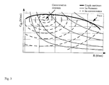
- la figure 3 est une cartographie faisant figurer les iso-consommations dans un diagramme donnant le couple du moteur thermique en fonction de son régime de rotation ;
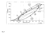
- la figure 4 est un diagramme donnant la puissance du moteur thermique en fonction de son régime de rotation, sur lequel on a représenté différents points de fonctionnement ;
- la figure 5 est un schéma représentant le fonctionnement de la commande d'accélérateur.
- Figure 1 is a general diagram of a power train for series hybrid vehicle according to the invention;
- FIG. 2 is a diagram giving the power of the heat engine as a function of its rotation speed, for different values of the PP actuator;
- FIG. 3 is a map showing the iso-consumptions in a diagram giving the torque of the heat engine as a function of its rotation speed;
- FIG. 4 is a diagram giving the power of the heat engine as a function of its rotational speed, on which various operating points have been represented;
- Figure 5 is a diagram showing the operation of the accelerator control.
A la figure 1, on voit un moteur thermique à essence 10, et un actionneur 15 contrôlant la
position d'un papillon dans une tubulure d'admission d'air. Le moteur thermique entraíne un
alternateur 11. L'énergie électrique fournie par ce dernier est distribuée vers quatre moteurs
électriques de traction 21, via un redresseur 13, une ligne électrique 12, et un onduleur 22 par
moteur 21. Un dispositif d'absorption 14 d'énergie électrique est connecté à la ligne
électrique 12.In FIG. 1, we see a
Une unité centrale 30 gère différentes fonctions, parmi lesquelles la chaíne de traction électrique
du véhicule (couple moteur ou freineur des moteurs électriques 21). L'unité centrale 30
comprend une unité de pilotage 31 du couple de propulsion des moteurs électriques 21 et un
dispositif électronique 32 de pilotage de l'actionneur 15 agissant sur la position du papillon PP,
ce qui agit sur la puissance développée par le moteur thermique 10. L'unité de pilotage 31 du
couple de propulsion du véhicule calcule ledit couple de consigne selon une période
d'échantillonnage choisie. L'unité centrale 30 reçoit des signaux d'évaluation de différents
paramètres comme un potentiomètre 40 reflétant la position d'une commande d'accélérateur CA
(une pédale ou autre commande équivalente à disposition du conducteur du véhicule), comme un
capteur 41 reflétant la position du papillon PP, un capteur 42 donnant la vitesse v du véhicule, un
capteur 43 donnant le régime R du moteur thermique, différents capteurs de température 44, un
capteur 45 donnant la pression du circuit hydraulique de freinage du véhicule, la liste étant non
exhaustive.A
Dans un véhicule réel, d'autres organes périphériques absorbent de la puissance délivrée par le
moteur thermique. En ce qui concerne la présente invention, il importe peu qu'ils prélèvent une
puissance mécanique directement au vilebrequin du moteur thermique ou qu'ils prélèvent une
puissance électrique sur la ligne électrique 12 car cela revient à prélever ladite puissance au
vilebrequin via l'alternateur. Indiquons simplement que certains de ces organes périphériques
peuvent aussi être gérés par l'unité centrale 30, ce qui présente l'intérêt de pouvoir tenir compte
des variations de puissance consommées dans le dispositif de pilotage 32 de l'actionneur 15
avant même que le régime du moteur thermique ait pu s'en trouver modifié.In a real vehicle, other peripheral organs absorb the power delivered by the
thermal motor. With regard to the present invention, it does not matter that they take a
mechanical power directly to the crankshaft of the heat engine or that they take a
electrical power on
Les moteurs électriques de traction 21 sont des moteurs synchrones triphasés, équipés d'un
capteur de position angulaire de type résolveur et sont pilotés par les onduleurs 22, sous le
contrôle de l'unité 31 de pilotage du couple de propulsion. L'électronique est conçue pour
piloter les moteurs en couple. De ce fait l'ensemble de traction peut être utilisé en moteur et en
frein.The
L'actionneur 15 est constituée essentiellement par un petit moteur électrique à courant continu,
accouplé au papillon des gaz du moteur thermique. Ce moteur est géré par une électronique et,
grâce à un capteur de position 41 (potentiomètre), le papillon est asservi en permanence en
position. La position papillon générée dépend bien entendu du couple souhaité pour le moteur
électrique de traction (couple qui peut être négatif), et est aussi adaptée en fonction d'une
éventuelle consommation trop importante par des organes périphériques.The
Un bus CAN® 50 (Controller Area Network) assure l'interconnexion des différents organes.
Ceci permet à l'unité centrale 30, choisie comme maítre du réseau, de recevoir notamment la
vitesse de la roue entraínée par le moteur électrique 21 et un diagnostic sur le fonctionnement en
provenance des onduleurs 22, et d'émettre un couple de consigne C à destination des onduleurs
22.A
Venons en à la description de la gestion du fonctionnement de la chaíne de traction. Le capteur
40 donnant la position de la pédale d'accélérateur délivre un signal qui permet de réaliser les 3
fonctions suivantes : accélération normale, accélération maximale possible (comparable à la
position dite « kick-down » dans les véhicules classiques à boíte de vitesses automatique), et
frein moteur. On laisse de côté pour le moment le fonctionnement en frein moteur.Let us come to the description of the management of the operation of the traction chain. The
Reportons-nous à la figure 2. On y voit un faisceau de courbes représentant la puissance réelle
Pthd du moteur thermique, en régime établi, pour différentes positions du papillon d'air. Ces
courbes sont représentatives de caractéristiques réelles d'un moteur à essence d'un véhicule de
tourisme. L'unité centrale 30 ne comporte aucune instruction programmée représentative de ces
caractéristiques réelles. Par ailleurs, on voit une courbe de pilotage P de la traction électrique
(puissance de pilotage). Cette courbe visualise des instructions programmées dans l'unité 31 de
pilotage du couple de propulsion.Refer to Figure 2. We see a bundle of curves representing the real power P thd of the heat engine, in steady state, for different positions of the air butterfly. These curves are representative of real characteristics of a gasoline engine of a passenger vehicle. The
Examinons différentes situations. On raisonne à partir d'un régime établi, quelconque mais loin
de la saturation en courant des moteurs de traction, et en négligeant la consommation d'énergie
par des organes périphériques. En fonction de ce régime, pour une certaine position du papillon,
le moteur délivre une certaine puissance qui doit être consommée par les moteurs électriques de
traction 21 pour que l'ensemble soit en équilibre. Par exemple, à 3100 tr/min et pour une
ouverture papillon à 40%, le moteur thermique délivre 18000 Watts (point de fonctionnement
1 ○), et la consigne couple C qui équilibre le système est la division de la puissance disponible par
la vitesse du véhicule.Let's look at different situations. We reason from an established regime, arbitrary but far
of the current saturation of the traction motors, and neglecting the energy consumption
by peripheral organs. According to this regime, for a certain position of the butterfly,
the motor delivers a certain power which must be consumed by the electric motors of
S'il n'y a pas égalité entre la puissance disponible et la puissance électrique consommée résultant de la consigne de couple C pilotée, le régime du moteur thermique va évoluer. Pour une courbe de pilotage P telle que celle de la figure 2, on constate qu'il y a autorégulation.If there is no equality between the available power and the consumed electric power resulting from the controlled torque setpoint C, the engine speed will change. For a piloting curve P such as that of FIG. 2, it can be seen that there is self-regulation.
Supposons que l'on parte du point de fonctionnement 1 ○ donné ci-dessus. Lorsque l'on enfonce
la pédale d'accélérateur, le dispositif de pilotage 32 ordonne à l'actionneur 15 d'ouvrir plus le
papillon d'air. Pour fixer les idées, si le papillon est réglé à 60 % d'ouverture suite à l'action du
conducteur sur l'accélérateur, au régime initial de 3100 tr/min, le moteur fournit réellement
27000 Watts (point de fonctionnement 2 ○). A l'instant initial, la puissance électrique consommée
par la traction n'ayant pas changé, la puissance électrique consommée par la traction est
inférieure à la puissance fournie par le moteur thermique. Le régime du moteur thermique 10 va
donc augmenter. Dès que le régime augmente, la consigne calculée pour le couple C augmente
automatiquement, comme déterminé par la courbe de pilotage P de la traction électrique. Celle-ci
donne une nouvelle valeur de la puissance à absorber par les moteurs électriques de traction 21,
ce qui compte tenu de la vitesse du véhicule donne immédiatement un nouveau couple de
consigne C. On voit que le moteur thermique va se stabiliser à un régime de 3800 tr/min (point
de fonctionnement 3 ○, à l'intersection de la courbe de pilotage P et la courbe caractéristique
réelle du moteur thermique pour une ouverture papillon à 60 %), régime auquel la puissance
électrique consommée par la traction est égale à la puissance fournie par le moteur thermique,
soit 31000 Watts.Suppose we start from the
Imaginons que l'on ramène la position du papillon à 40 % d'ouverture. Au régime initial de 3800
tr/min, le moteur ne peut plus fournir que 21000 Watts (point de fonctionnement 4 ○). La
puissance électrique consommée par la traction étant restée supérieure à la puissance fournie par
le moteur thermique, ce dernier va perdre des tours et se stabiliser à un régime de 3100 tr/min
(point de fonctionnement 1 ○, à l'intersection de la courbe de pilotage P et la courbe
caractéristique réelle du moteur thermique pour une ouverture papillon à 40 %), régime auquel la
puissance électrique consommée par la traction est égale à la puissance fournie par le moteur
thermique, soit 18000 Watts.Imagine that we reduce the position of the butterfly to 40% opening. At the initial regime of 3800
rpm, the motor can only supply 21000 Watts (
Par ce principe, on assure que la puissance n'est consommée que lorsqu'elle est réellement disponible (pas de calage ni d'emballement du moteur thermique). Le fonctionnement de la chaíne de traction est stable car, pour une courbe de pilotage P de la traction électrique telle que montrée à la figure 2, même sans connaítre les caractéristiques réelles du moteur thermique (celles-ci peuvent évoluer au cours du temps notamment en fonction de l'usure), à chaque position du papillon, il y a un seul point de fonctionnement sur ladite courbe de pilotage P. Autrement dit, il est avantageux (car c'est une façon de garantir un fonctionnement toujours stable) que, pour toutes les positions de l'actionneur PP, la courbe de puissance de pilotage P choisie ait une seule intersection avec la courbe de puissance réellement disponible Pthd. De préférence, la courbe de pilotage P choisie rejoint la courbe de caractéristiques réelles du moteur thermique pour une ouverture papillon de 100 % au régime de puissance maximale du moteur thermique.By this principle, it is ensured that the power is consumed only when it is actually available (no stalling or runaway of the heat engine). The operation of the traction chain is stable because, for a control curve P of the electric traction as shown in Figure 2, even without knowing the real characteristics of the heat engine (these can change over time, in particular function of wear), at each throttle position, there is only one operating point on said piloting curve P. In other words, it is advantageous (because it is a way of guaranteeing always stable operation) that, for all the positions of the actuator PP, the piloting power curve P chosen has a single intersection with the power curve actually available P thd . Preferably, the piloting curve P chosen joins the curve of real characteristics of the heat engine for a throttle opening of 100% at the maximum power speed of the heat engine.
Pour des vitesses véhicule faibles, on a vu qu'il n'est pas possible de consommer toute la puissance disponible car, comme on l'a déjà exposé, les moteurs électriques sont limités en courant, donc en couple. Plus généralement, d'autres causes de limitation du couple du moteur électrique de traction pourraient intervenir. Citons l'exemple d'une fonction anti-patinage.For low vehicle speeds, we have seen that it is not possible to consume all of the available power because, as already explained, electric motors are limited in current, so as a couple. More generally, other causes of engine torque limitation electric traction could intervene. Let us cite the example of an anti-skid function.
De façon avantageuse, afin d'améliorer la finesse de fonctionnement du système, la valeur de la
limite de la position papillon peut être adaptée par le correcteur suivant : les moyens de pilotage
de l'actionneur 15 calculent en permanence, à chaque itération, une position limite comme suit :
Limite position papillon = Position papillon maxi - k *(Pthd - Pa - Pt)Advantageously, in order to improve the smoothness of operation of the system, the value of the limit of the throttle position can be adapted by the following corrector: the control means of the
Le terme Pt est la puissance utilisée pour la traction du véhicule et le terme Pa est une puissance annexe, non utilisée pour la traction. On a déjà évoqué la consommation de puissance par les organes périphériques. Il est avantageux de tenir également compte de différentes pertes comme on va l'expliquer ci-dessous. L'ensemble des pertes et de la puissance consommée par les organes périphériques est la puissance annexe visée ici.The term P t is the power used for traction of the vehicle and the term P a is an auxiliary power, not used for traction. We have already mentioned the consumption of power by the peripheral organs. It is advantageous to also take into account different losses as will be explained below. All the losses and the power consumed by the peripheral organs is the additional power referred to here.
On a vu que le calcul du couple de consigne C sur la base de la puissance de pilotage P converge
toujours vers un fonctionnement stable. L'homme du métier aura compris que l'on converge
d'autant plus vite que l'on peut dans le calcul mieux tenir compte des causes de variations de
puissances autres que celles résultant des actions du conducteur du véhicule. Dans cette variante,
on propose de tenir compte d'une puissance annexe non utile à la traction (terme Pa). Les pertes
sont la somme des pertes fer, des pertes par effet Joule, à l'alternateur et au moteur électrique de
traction, des pertes dans les onduleurs, au redresseur, et d'autres encore. On peut modéliser
toutes ces pertes des organes électriques cités (mesures, expérimentations, calculs, ...). Cette
modélisation peut être chargée dans l'unité centrale 30, et la mesure ou la connaissance des
différents paramètres comme la température de fonctionnement des différents organes, les
vitesses de rotation, les courants électriques, le couple de consigne C, permettent de calculer un
terme Pa (Puissance annexe) à chaque itération.We have seen that the calculation of the setpoint torque C on the basis of the piloting power P always converges towards stable operation. A person skilled in the art will have understood that one converges all the faster as one can in the calculation better take into account the causes of variations in power other than those resulting from the actions of the driver of the vehicle. In this variant, it is proposed to take account of an annex power which is not useful for traction (term P a ). The losses are the sum of the iron losses, losses by the Joule effect, at the alternator and the electric traction motor, losses in the inverters, the rectifier, and others still. We can model all these losses of the cited electrical organs (measurements, experiments, calculations, ...). This modeling can be loaded into the
On peut qualifier le fonctionnement selon la courbe de pilotage P exposé ci-dessus de dynamique, parce qu'il assure une excellente réponse à l'accélérateur, un peu comme sur les rapports de vitesses les plus courts avec un véhicule classique à boíte de vitesse mécanique.We can qualify the operation according to the piloting curve P exposed above of dynamic, because it provides an excellent response to the accelerator, much like on shortest gear ratios with a conventional vehicle with a mechanical gearbox.
Mais on sait par ailleurs que le rendement thermodynamique d'un moteur thermique classique n'est pas indépendant de sa charge, c'est à dire de l'ouverture papillon pour un moteur à essence. But we also know that the thermodynamic efficiency of a conventional heat engine is not independent of its load, i.e. the throttle opening for a petrol engine.
Comme le montre la figure 3 donnant en ordonnées le couple Cth du moteur thermique et en abscisses le régime R du moteur thermique, la consommation spécifique d'un moteur thermique varie avec le régime et la charge du moteur thermique. Pour une puissance disponible Pthd donnée, le point de fonctionnement offrant le minimum de consommation de carburant se situe plutôt aux régimes moteurs faibles et, on le sait, à ouverture papillon élevée.As shown in FIG. 3 giving on the ordinate the torque C th of the heat engine and on the abscissa the speed R of the heat engine, the specific consumption of a heat engine varies with the speed and the load of the heat engine. For a given available power P thd , the operating point offering the minimum fuel consumption is rather at low engine speeds and, as we know, at high throttle opening.
On va décrire maintenant une réalisation avantageuse dont l'objectif est de toujours tendre vers une moindre consommation de carburant. Il s'agit de faire évoluer le point de fonctionnement vers une charge moteur plus élevée, sans préjudice d'une bonne réponse à l'accélérateur. On propose ci-dessous les moyens pour que le pilotage évolue automatiquement entre un pilotage économique et un pilotage dynamique.We will now describe an advantageous achievement whose objective is to always strive towards lower fuel consumption. It is about changing the operating point towards a higher engine load, without prejudice to a good response to the accelerator. We offers below the means so that the piloting evolves automatically between a piloting economical and dynamic steering.
Ayant observé qu'une zone de fonctionnement favorable en consommation se situe à un régime plutôt bas et une ouverture papillon plutôt grande, on utilise aussi une courbe de puissance de pilotage économique PE (également appelée plus simplement « pilotage économique ») telle que tracée à la figure 4. A la figure 4, on a aussi reporté une courbe de puissance de pilotage comparable à celle de la figure 2, dite courbe de pilotage dynamique PD. Entre les courbes PE et PD, on s'aperçoit que la même puissance peut être obtenue à des points de fonctionnement différents.Having observed that a favorable operating zone in consumption is at a regime rather low and a rather large butterfly opening, we also use a power curve of PE economic steering (also more simply called “economic steering”) such that plotted in Figure 4. In Figure 4, we have also reported a piloting power curve comparable to that of FIG. 2, called the dynamic piloting curve PD. Between PE curves and PD, we see that the same power can be obtained at operating points different.
La courbe de pilotage PD de la figure 4 est la même que la courbe de pilotage P de la figure 2. Sur cette courbe, on voit qu'une puissance de 30000 Watts est obtenue à un régime d'environ 3750 tr/min et une position papillon voisine de 60 % d'ouverture (point de fonctionnement « B »), alors que sur la courbe PE, on voit que la même puissance de 30000 Watts est obtenue à un régime d'environ 2500 tours/minute et une position papillon voisine de 80% d'ouverture (point de fonctionnement « A »).The piloting curve PD of FIG. 4 is the same as the piloting curve P of FIG. 2. On this curve, we see that a power of 30,000 Watts is obtained at a speed of approximately 3750 rpm and a throttle position close to 60% opening (operating point "B"), while on the PE curve, we see that the same power of 30,000 Watts is obtained at a speed of around 2500 rpm and a throttle position close to 80% opening (operating point "A").
Si la programmation de l'unité 31 de pilotage du couple de propulsion est basée uniquement sur
une telle courbe de pilotage économique PE, et que le conducteur éprouve le besoin d'accélérer,
la réaction de la chaíne globale de traction à une action appropriée sur la commande
d'accélérateur CA est plus lente que la réaction à la même action appropriée sur la commande
d'accélérateur CA dans le cas où la programmation de l'unité 31 de pilotage du couple de
propulsion est basée sur la courbe de pilotage dynamique PD. En effet, dans le premier cas,
l'actionneur PP est dans une position bien plus proche de l'ouverture papillon maximale que
dans le deuxième cas. La réserve d'accélération est bien moindre dans le cas du pilotage
économique que dans le cas du pilotage dynamique. Dès lors, dans le cas du pilotage
économique, le moteur thermique met beaucoup plus de temps pour monter en régime et donner
une puissance supérieure. En conséquence, la consigne couple C augmente moins vite et le
véhicule accélère moins fort. La réponse à l'accélérateur est lente, un peu comme sur les rapports
de vitesses les plus longs avec un véhicule classique à boíte de vitesse mécanique.If the programming of the propulsion
C'est pourquoi il est proposé, dans une variante de réalisation très avantageuse, d'utiliser en fait
un ensemble de courbes de pilotage, afin de varier automatiquement et progressivement de la
courbe de pilotage dynamique PD à la courbe de pilotage économique PE, ces deux courbes étant
les limites du fonctionnement de la chaíne de traction. Cela signifie que le pilotage effectif va
varier automatiquement entre un mode limite qui optimise le caractère dynamique de la réponse
à une demande d'accélération, et un autre mode limite qui optimise le rendement énergétique. La
courbe de pilotage programmée dans l'unité 31 de pilotage du couple de propulsion est la
suivante :
De préférence, on choisit le paramètre « Réglage » en fonction des courbes caractéristiques du fonctionnement du moteur thermique utilisé.Preferably, the "Adjustment" parameter is chosen according to the characteristic curves of the operation of the thermal engine used.
A titre d'exemple non limitatif, on définit fort correctement un pilotage selon une courbe de pilotage dynamique PD pour une valeur du paramètre « Réglage » de l'ordre de 1.5 (= Réglage dynamique), et on définit fort correctement un pilotage selon une courbe de pilotage économique PE pour une valeur du paramètre « Réglage » de l'ordre de 0.7 (Réglage économique). Les valeurs données ci-dessus ne sont qu'indicatives. Il convient de les déterminer au mieux, par exemple expérimentalement, en fonction de chaque cas. Une valeur élevée de ce paramètre correspond à un pilotage dynamique, alors qu'une valeur faible correspond à un pilotage économique. By way of nonlimiting example, steering is very correctly defined according to a curve of PD dynamic control for a value of the "Adjustment" parameter of the order of 1.5 (= Adjustment dynamic), and steering is very correctly defined according to an economic steering curve PE for a value of the "Adjustment" parameter of the order of 0.7 (Economic adjustment). The values given above are only indicative. They should be best determined by example experimentally, depending on each case. A high value for this parameter corresponds to dynamic control, while a low value corresponds to control economic.
Les modes limites étant déterminés, on peut très aisément faire varier automatiquement le paramètre « Réglage » de la façon suivante : le paramètre « Réglage », à partir d'une valeur maximale « Réglage dynamique » choisie pour assurer un pilotage dynamique, tend toujours vers la valeur « Réglage économique » , sauf en cas de demande d'accélération par le conducteur..The limit modes being determined, it is very easy to automatically vary the “Adjustment” parameter as follows: the “Adjustment” parameter, from a value maximum "Dynamic adjustment" chosen to ensure dynamic steering, always tends towards the value "Economic adjustment", except in the event of an acceleration request by the driver.
Ceci permet d'évoluer automatiquement vers la courbe PE quand le conducteur n'accélère pas, et d'évoluer automatiquement vers la courbe PD lorsque le conducteur accélère, et réciproquement.This makes it possible to automatically evolve towards the PE curve when the driver is not accelerating, and automatically evolve towards the PD curve when the driver accelerates, and vice versa.
Ceci peut se faire en temps réel, pendant le roulage, grâce par exemple à une analyse simple d'informations pertinentes pour apprécier le style de conduite du véhicule par le conducteur. On peut tenir compte par exemple de la vitesse du véhicule, de la position de la commande d'accélérateur CA, et surtout des variations de cette position, notamment des vitesses de variation, du temps écoulé depuis la dernière variation.This can be done in real time, during taxiing, thanks for example to a simple analysis relevant information to assess the driving style of the vehicle by the driver. We can take into account for example the vehicle speed, the position of the control AC accelerator, and above all variations of this position, in particular variation, the time since the last variation.
Dans une autre variante de réalisation, on introduit une limite basse pour le paramètre
« Réglage » afin de conférer au véhicule une grande souplesse de manoeuvre à faible vitesse. Le
paramètre « Réglage », évolue alors entre une valeur haute dite « Réglage dynamique » et une
valeur basse dite « Réglage mini », avec « Réglage mini » calculé de la façon suivante :

On a constaté que cela permet d'améliorer l'agrément du véhicule dans les manoeuvres à vitesse faible. La conduite est rendue plus souple par une courbe de pilotage restant plutôt dynamique à basse vitesse. Le seuil vitesse est fixé entre 15 et 30 km/h, par exemple à 20 km/h. Au dessus du seuil vitesse, la gestion du paramètre « Réglage » autorise le pilotage économique.It has been found that this improves the approval of the vehicle in speed maneuvers. low. Driving is made more flexible by a steering curve which remains rather dynamic at low speed. The speed threshold is set between 15 and 30 km / h, for example at 20 km / h. Above speed threshold, management of the "Adjustment" parameter authorizes economic management.
Dans la variante de réalisation suivante, on donne un cas pratique de programmation de l'unité 31 de pilotage du couple de propulsion qui permet de rendre la réaction de la chaíne de traction aussi dynamique que possible lorsque le conducteur manifeste une volonté de forte accélération par une variation rapide de la position de la pédale d'accélérateur. On utilise la dérivée de la position de la commande d'accélérateur CA pour réaliser cette fonction. La valeur de cette dérivée permet de se rapprocher plus ou moins rapidement de la courbe de pilotage dynamique PD. Après une certaine temporisation, on retourne progressivement vers la courbe de pilotage économique PE.In the following alternative embodiment, a practical case of programming the unit is given. 31 driving the propulsion torque which makes the reaction of the traction chain as dynamic as possible when the driver shows a desire for strong acceleration by a rapid variation of the position of the accelerator pedal. We use the derivative of the position of the AC accelerator control to perform this function. The value of this derivative allows you to approach the dynamic steering curve more or less quickly PD. After a certain delay, we gradually return to the steering curve economic PE.
Consultons à nouveau la figure 4. Supposons que, au départ, on se trouve au point de
fonctionnement 1 ○ sur la courbe de pilotage économique PE. L'ouverture papillon est à 60 % et
le régime est à 1200 tr/min, le moteur fournissant 9000 Watts. Le conducteur souhaite une
accélération importante, il appuie brusquement sur la pédale d'accélérateur et lui donne une
position telle que l'ouverture papillon devient 80 %. L'analyse de la dérivée du signal donnant la
position de la pédale d'accélérateur au cours du temps, par exemple par comparaison à un seuil,
a fait basculer sur une courbe de pilotage plus dynamique, c'est à dire tendant vers une courbe
telle que PD, alors que le papillon est encore en train de changer de position. La puissance
pilotée effectivement est celle correspondant au point de fonctionnement 2 ○, soit 2000 Watts. Il
n'y a à ce moment plus équilibre entre la puissance fournie par le moteur thermique et la
puissance selon laquelle on pilote les moteurs électriques de traction 21. Le moteur thermique
monte donc en régime, ce qui permet l'accélération du véhicule comme on l'a expliqué à
l'occasion de la description de la figure 2.Let's look again at Figure 4. Suppose that, at the start, we are at the point of
Pour prendre une image, le passage du point de fonctionnement 1 ○ vers le point de
fonctionnement 2 ○ correspond à rétrograder avec une boíte de vitesse manuelle dans un véhicule
courant. On se retrouve rapidement au point de fonctionnement 3 ○. Après une temporisation
judicieuse, on peut revenir progressivement vers une courbe de pilotage plus économique. Pour
simplifier l'exposé, on peut supposer que le point de pilotage évolue vers le point 4 ○. De
nouveau, il n'y a plus équilibre entre la puissance fournie par le moteur thermique et la puissance
déterminant le couple de consigne C. Le moteur thermique 10 est trop chargé. Comme l'unité 31
de pilotage du couple de propulsion travaille maintenant selon la courbe de pilotage économique
PE, les puissances vont s'équilibrer au point 5 ○, après une baisse du régime du moteur thermique
10, à position papillon sensiblement constante. En fait, bien entendu, comme les changements de
courbe de pilotage sont continus, l'évolution du point de fonctionnement n'est pas aussi abrupte
que la lecture de la figure 4 qui vient d'être proposée le laisse supposer.To take an image, passing from
On peut obtenir le fonctionnement qui vient d'être décrit par l'évolution de programmation
suivante :

Dans certaines conditions, le conducteur peut avoir besoin de toute la puissance durant une
longue période. C'est le cas par exemple pour un dépassement. Il est donc avantageux de pouvoir
programmer l'unité 31 de pilotage du couple de propulsion pour obtenir l'effet « Kick down »
bien connu pour les boítes de vitesses automatiques des véhicules conventionnels. Le conducteur
manifeste son désir par un enfoncement de la commande d'accélérateur CA, allant jusqu'à fond
de course, et en maintenant l'enfoncement complet tant que l'on souhaite disposer de toute la
puissance.Under certain conditions, the driver may require full power during a
long period. This is the case for example for an overshoot. It is therefore advantageous to be able
program the propulsion
On utilise bien entendu la courbe de pilotage la plus dynamique possible, à savoir la courbe PD.
L'ouverture papillon devient maximale, dans les limites expliquées ci-dessus (saturation du
moteur électrique de traction, anti-patinage, ...). Et dans ce cas, le paramètre k garde la valeur 1
tant que le conducteur maintient la pédale d'accélérateur enfoncée. On reste au point de
fonctionnement à ouverture maximale de l'actionneur PP, et ce aussi longtemps que la pédale
d'accélérateur reste enfoncée.Of course, the most dynamic control curve possible, namely the PD curve, is used.
The throttle opening becomes maximum, within the limits explained above (saturation of the
electric traction motor, traction control, ...). And in this case, the parameter k keeps the
Dans un mode particulier de réalisation, on peut faire fonctionner les moteurs électriques de
traction en générateurs, afin de fournir un effet comparable au frein moteur d'un véhicule
conventionnel. Le véhicule est alors équipé d'un dispositif d'absorption d'énergie électrique
branché sur ladite ligne électrique via une unité de contrôle de freinage 14. L'unité de contrôle
de freinage 14 détecte automatiquement un transfert d'énergie allant dans le sens de la
récupération et la dirige dans le dispositif d'absorption d'énergie électrique. Puisque l'on est en
freinage, le fonctionnement de l'unité de pilotage du couple 31 a déjà fait prendre à l'actionneur
PP une position de ralenti (pour plus de détails, voir la description de la figure 5 ci-dessous). De
la sorte, il y a absorption de l'énergie électrique délivrée par ledit moteur électrique de traction
lorsqu'il fonctionne en alternateur et qu'il applique au véhicule un effort de freinage.In a particular embodiment, the electric motors of
traction in generators, to provide an effect comparable to the engine brake of a vehicle
conventional. The vehicle is then equipped with an electrical energy absorption device
connected to said electrical line via a
L'énergie électrique fournie par le ou les moteurs électriques de traction 10, lorsqu'ils
fonctionnent en générateurs, est consommée par une charge branchée sur la ligne électrique 12.
L'invention présentant la particularité que le pilotage de la chaíne de traction est conçu pour
pouvoir fonctionner sans batterie d'accumulateurs en tampon entre l'alternateur 11 et les
moteurs électriques 21, le dispositif d'absorption d'énergie électrique peut être une simple
résistance électrique 140 de dissipation de l'énergie de freinage. Il est proposé que ledit seuil
prédéterminé de la commande d'accélérateur CA soit proportionnel à la vitesse du véhicule.The electric energy supplied by the electric traction motor or
A la figure 5, les abscisses représentent la position de commande d'accélérateur CA à la disposition du conducteur du véhicule, et les ordonnées représentent la traduction de cette position en commande d'accélération effective CAe (positive ou négative, et quantifiée). On voit un faisceau de courbes, chaque courbe correspondant à une vitesse du véhicule. Toutes les courbes (sauf une, correspondant à une vitesse de déplacement du véhicule nulle) ont une première partie dans laquelle la demande d'accélération est négative et variable, une deuxième partie dans laquelle la demande d'accélération est positive et variable, et enfin une troisième partie dans laquelle la demande d'accélération est positive et constante.In FIG. 5, the abscissa represents the accelerator control position CA available to the driver of the vehicle, and the ordinate represents the translation of this position into effective acceleration control CA e (positive or negative, and quantified). We see a bundle of curves, each curve corresponding to a vehicle speed. All the curves (except one, corresponding to a zero speed of movement of the vehicle) have a first part in which the acceleration demand is negative and variable, a second part in which the acceleration demand is positive and variable, and finally a third part in which the demand for acceleration is positive and constant.
Les demandes d'accélérations positives permettent à l'unité de pilotage du couple 31 de
déterminer un couple de consigne C comme expliqué ci-dessus. Les demandes d'accélérations
négatives permettent à l'unité de pilotage du couple 31 de piloter le dispositif d'absorption
d'énergie 14, d'envoyer une consigne « ralenti » au dispositif de pilotage de l'actionneur PP
(sauf si d'autres organes périphériques branchées sur la ligne 12 demandent plus d'énergie
électrique que ce que les moteurs électriques 21 fournissent en phase de frein moteur), et
d'envoyer aux onduleurs 22 une consigne de couple C négative, plus ou moins importante. Le
couple de freinage (pour rappel, les moteurs 21 sont pilotés en couple) est donc fonction de la
position de la pédale d'accélérateur et de la vitesse instantanée du véhicule (voir figure 5). Bien
entendu, il convient de limiter le couple de consigne C en fonction du courant maximal
admissible par le ou les moteurs électriques de traction 21 et en fonction de la puissance
maximale acceptable par la résistance de dissipation ou un dispositif d'absorption d'énergie
équivalent installé sur le véhicule. Positive acceleration requests allow the
Qualifions de « position neutre » la position de la commande d'accélérateur CA pour laquelle la demande d'accélération est nulle. Cette position dépend de la vitesse du véhicule. Lorsque la position de la pédale est inférieure à la position neutre, la chaíne de traction fonctionne en frein moteur. Qualifions de « position kick-down » toute position de la commande d'accélérateur CA de la troisième partie des courbes de la figure 5, dans laquelle la demande d'accélération est positive et constante. Entre la position neutre et la position kick-down, le fonctionnement de la chaíne de traction est celui expliqué ci-dessus, avec adaptation automatique et constante entre un pilotage dynamique PD et un pilotage économique PE. Le fonctionnement dans la zone kick-down a aussi été expliqué ci-dessus.Let us call the position of the AC accelerator control for which the acceleration request is zero. This position depends on the speed of the vehicle. When the pedal position is lower than neutral position, the traction chain operates in brake engine. Qualify as a kick-down position any position on the AC throttle control of the third part of the curves of Figure 5, in which the acceleration demand is positive and consistent. Between the neutral position and the kick-down position, the operation of the traction chain is the one explained above, with automatic and constant adaptation between a PD dynamic steering and PE economic steering. Operation in the kick-down zone has also been explained above.
A vitesse nulle, par exemple, le neutre est au zéro de la pédale d'accélérateur, il n'y a donc pas de zone frein moteur et donc pas de possibilité de faire du freinage électrique. Lorsque la vitesse du véhicule augmente, le neutre se déplace, la zone de freinage augmente et celle de traction diminue.At zero speed, for example, neutral is at zero on the accelerator pedal, so there is no motor brake zone and therefore no possibility of electric braking. When the speed of the vehicle increases, the neutral moves, the braking zone increases and that of traction decreases.
Avantageusement, afin de faciliter les démarrages en côte ou de maintenir le véhicule dans une pente, lorsque la commande d'accélérateur CA est au repos et que la vitesse de déplacement du véhicule est nulle, tant que le conducteur du véhicule ne sollicite pas la commande d'accélérateur CA, l'unité de pilotage du couple de propulsion calcule un couple de consigne C de façon à maintenir à une valeur nulle la vitesse du véhicule.Advantageously, in order to facilitate hill starts or to keep the vehicle in a slope, when the accelerator control CA is at rest and the speed of movement of the vehicle is void, as long as the driver of the vehicle does not request the command AC accelerator, the drive torque control unit calculates a setpoint torque C so as to maintain the speed of the vehicle at zero.
Bien entendu, pour récupérer de l'énergie au freinage, on pourrait utiliser un moyen de stockage
de l'énergie électrique, comme une batterie d'accumulateurs électrochimiques, ou tout dispositif
équivalent. Avantageusement, la capacité de stockage est modérée (pour ne pas alourdir le
véhicule), et le dispositif de pilotage 32 tend à d'abord vider la batterie en cas de demande
d'accélération du véhicule indiquée par la commande d'accélérateur CA, avant d'agir sur
l'actionneur PP.Of course, to recover energy from braking, we could use storage
electrical energy, such as an electrochemical storage battery, or any device
equivalent. Advantageously, the storage capacity is moderate (so as not to weigh down the
vehicle), and the
Claims (11)


Applications Claiming Priority (2)
| Application Number | Priority Date | Filing Date | Title |
|---|---|---|---|
| FR0103494 | 2001-03-14 | ||
| FR0103494 | 2001-03-14 |
Publications (1)
| Publication Number | Publication Date |
|---|---|
| EP1241043A1 true EP1241043A1 (en) | 2002-09-18 |
Family
ID=8861135
Family Applications (1)
| Application Number | Title | Priority Date | Filing Date |
|---|---|---|---|
| EP02004997A Withdrawn EP1241043A1 (en) | 2001-03-14 | 2002-03-06 | Series hybrid vehicle, capable to drive without batteries |
Country Status (4)
| Country | Link |
|---|---|
| US (1) | US6692403B2 (en) |
| EP (1) | EP1241043A1 (en) |
| JP (1) | JP3790964B2 (en) |
| CA (1) | CA2374801A1 (en) |
Cited By (4)
| Publication number | Priority date | Publication date | Assignee | Title |
|---|---|---|---|---|
| EP1428712A1 (en) | 2002-12-11 | 2004-06-16 | Conception et Développement Michelin S.A. | Drivetrain and control method for series hybrid vehicle |
| WO2013068808A1 (en) * | 2011-11-10 | 2013-05-16 | Toyota Jidosha Kabushiki Kaisha | Vehicle and vehicle control method |
| WO2013076566A1 (en) * | 2011-11-24 | 2013-05-30 | Toyota Jidosha Kabushiki Kaisha | Vehicle and control method for vehicle |
| EP3363670B1 (en) * | 2017-02-21 | 2022-03-30 | Iveco S.p.A. | Method and device for managing the propulsion of a parallel hybrid vehicle |
Families Citing this family (18)
| Publication number | Priority date | Publication date | Assignee | Title |
|---|---|---|---|---|
| JP4114788B2 (en) * | 2003-03-13 | 2008-07-09 | 本田技研工業株式会社 | Hybrid working machine |
| JP3843966B2 (en) * | 2003-06-05 | 2006-11-08 | アイシン・エィ・ダブリュ株式会社 | Hybrid vehicle drive control device, hybrid vehicle drive control method and program thereof |
| JP4097570B2 (en) * | 2003-06-25 | 2008-06-11 | トヨタ自動車株式会社 | Vehicle connector routing structure |
| JP4217192B2 (en) * | 2004-06-01 | 2009-01-28 | 富士重工業株式会社 | Control device for hybrid vehicle |
| EP1794016A1 (en) * | 2004-09-30 | 2007-06-13 | MTD Products Inc. | Hybrid utility vehicle |
| US7600595B2 (en) | 2005-03-14 | 2009-10-13 | Zero Emission Systems, Inc. | Electric traction |
| US7543454B2 (en) * | 2005-03-14 | 2009-06-09 | Zero Emission Systems, Inc. | Method and auxiliary system for operating a comfort subsystem for a vehicle |
| JP2006307797A (en) * | 2005-05-02 | 2006-11-09 | Yamaha Motor Co Ltd | Control device and method for controlling saddle-mounted vehicle engine |
| US7921945B2 (en) | 2006-02-21 | 2011-04-12 | Clean Emissions Technologies, Inc. | Vehicular switching, including switching traction modes and shifting gears while in electric traction mode |
| US8565969B2 (en) | 2007-04-03 | 2013-10-22 | Clean Emissions Technologies, Inc. | Over the road/traction/cabin comfort retrofit |
| US7921950B2 (en) * | 2006-11-10 | 2011-04-12 | Clean Emissions Technologies, Inc. | Electric traction retrofit |
| JP2011520675A (en) * | 2008-03-19 | 2011-07-21 | ゼロ・エミッション・システムズ・インコーポレーテッド | Electric traction system and method |
| US9758146B2 (en) * | 2008-04-01 | 2017-09-12 | Clean Emissions Technologies, Inc. | Dual mode clutch pedal for vehicle |
| JP5307604B2 (en) * | 2009-04-08 | 2013-10-02 | アイシン・エーアイ株式会社 | Vehicle power transmission control device |
| US9631528B2 (en) | 2009-09-03 | 2017-04-25 | Clean Emissions Technologies, Inc. | Vehicle reduced emission deployment |
| DE102013013860A1 (en) * | 2013-08-20 | 2015-02-26 | Audi Ag | Vehicle drive control |
| GB2555834A (en) * | 2016-11-11 | 2018-05-16 | Airbus Operations Ltd | Braking energy dissipation |
| IT201800002779A1 (en) * | 2018-02-16 | 2019-08-16 | Iveco Spa | PROPULSION CONTROL METHOD AND DEVICE OF A VEHICLE INCLUDING AN ELECTRIC PROPULSION GENERATOR |
Citations (3)
| Publication number | Priority date | Publication date | Assignee | Title |
|---|---|---|---|---|
| US5935040A (en) * | 1996-07-23 | 1999-08-10 | Toyota Jidosha Kabushiki Kaisha | Hybrid vehicle drive system adapted to produce substantially constant vehicle drive force under the same vehicle running condition, even in different modes of operation |
| US5993351A (en) * | 1997-12-05 | 1999-11-30 | Nissan Motor Co., Ltd. | Control device for hybrid vehicle |
| US6155954A (en) * | 1998-09-22 | 2000-12-05 | Nissan Motor Co., Ltd. | Engine output control device for hybrid vehicle |
Family Cites Families (7)
| Publication number | Priority date | Publication date | Assignee | Title |
|---|---|---|---|---|
| US5762156A (en) * | 1995-10-31 | 1998-06-09 | Ford Global Technologies, Inc. | Hybrid electric propulsion system using a dual shaft turbine engine |
| US5761028A (en) * | 1996-05-02 | 1998-06-02 | Chrysler Corporation | Transistor connection assembly having IGBT (X) cross ties |
| EP1022182B1 (en) * | 1999-01-20 | 2011-03-16 | Voith Turbo GmbH & Co. KG | Drive system for automobile, especially for commercial vehicles, and electrical unit |
| US6163121A (en) * | 1999-01-29 | 2000-12-19 | General Electric Company | Torque maximization and vibration control for AC locomotives |
| US6104148A (en) * | 1999-04-15 | 2000-08-15 | General Electric Company | System and method for controlling an AC traction motor without sensing motor rotation speed |
| US6484830B1 (en) * | 2000-04-26 | 2002-11-26 | Bowling Green State University | Hybrid electric vehicle |
| US6359346B1 (en) * | 2000-08-23 | 2002-03-19 | General Electric Company | Processor and method for accommodating failed speed sensors in a locomotive |
-
2002
- 2002-03-06 EP EP02004997A patent/EP1241043A1/en not_active Withdrawn
- 2002-03-08 CA CA002374801A patent/CA2374801A1/en not_active Abandoned
- 2002-03-13 US US10/097,021 patent/US6692403B2/en not_active Expired - Fee Related
- 2002-03-14 JP JP2002070646A patent/JP3790964B2/en not_active Expired - Fee Related
Patent Citations (3)
| Publication number | Priority date | Publication date | Assignee | Title |
|---|---|---|---|---|
| US5935040A (en) * | 1996-07-23 | 1999-08-10 | Toyota Jidosha Kabushiki Kaisha | Hybrid vehicle drive system adapted to produce substantially constant vehicle drive force under the same vehicle running condition, even in different modes of operation |
| US5993351A (en) * | 1997-12-05 | 1999-11-30 | Nissan Motor Co., Ltd. | Control device for hybrid vehicle |
| US6155954A (en) * | 1998-09-22 | 2000-12-05 | Nissan Motor Co., Ltd. | Engine output control device for hybrid vehicle |
Cited By (9)
| Publication number | Priority date | Publication date | Assignee | Title |
|---|---|---|---|---|
| EP1428712A1 (en) | 2002-12-11 | 2004-06-16 | Conception et Développement Michelin S.A. | Drivetrain and control method for series hybrid vehicle |
| US7096098B2 (en) | 2002-12-11 | 2006-08-22 | Conception Et Developpement Michelin S.A. | Traction chain for a series hybrid vehicle |
| WO2013068808A1 (en) * | 2011-11-10 | 2013-05-16 | Toyota Jidosha Kabushiki Kaisha | Vehicle and vehicle control method |
| CN103917391A (en) * | 2011-11-10 | 2014-07-09 | 丰田自动车株式会社 | Vehicle and vehicle control method |
| CN103917391B (en) * | 2011-11-10 | 2016-05-04 | 丰田自动车株式会社 | Vehicle and control method for vehicle |
| WO2013076566A1 (en) * | 2011-11-24 | 2013-05-30 | Toyota Jidosha Kabushiki Kaisha | Vehicle and control method for vehicle |
| CN103958243A (en) * | 2011-11-24 | 2014-07-30 | 丰田自动车株式会社 | Vehicle and control method for vehicle |
| CN103958243B (en) * | 2011-11-24 | 2016-11-02 | 丰田自动车株式会社 | Vehicle and the control method for vehicle |
| EP3363670B1 (en) * | 2017-02-21 | 2022-03-30 | Iveco S.p.A. | Method and device for managing the propulsion of a parallel hybrid vehicle |
Also Published As
| Publication number | Publication date |
|---|---|
| CA2374801A1 (en) | 2002-09-14 |
| JP3790964B2 (en) | 2006-06-28 |
| JP2002369312A (en) | 2002-12-20 |
| US6692403B2 (en) | 2004-02-17 |
| US20020183161A1 (en) | 2002-12-05 |
Similar Documents
| Publication | Publication Date | Title |
|---|---|---|
| EP1241043A1 (en) | Series hybrid vehicle, capable to drive without batteries | |
| EP1428712B1 (en) | Drivetrain and control method for series hybrid vehicle | |
| EP1853472A1 (en) | Method for fast starting of a hybrid vehicle | |
| FR2956637A1 (en) | METHOD FOR MANAGING A DRIVE SYSTEM FOR A MOTOR VEHICLE | |
| CH687307A5 (en) | Propulsion of a vehicle. | |
| FR2973872A1 (en) | DEVICE AND METHOD FOR MANAGING A MOTOR VEHICLE | |
| FR2809352A1 (en) | Drive unit for a hybrid vehicle, has arrangement which ensures smooth torque during the changeover from series to parallel mode and vice-versa | |
| EP3074257B1 (en) | Method and system for starting a combustion engine | |
| EP1255175A1 (en) | Method for designing the control laws of an infinitely variable hybrid drivetrain for motor vehicles | |
| WO2001025049A1 (en) | Control method for hybrid vehicle | |
| FR2992040A1 (en) | METHOD AND DEVICE FOR CONTROLLING THE ENGAGED SPEED OF AN AUTOMATED VEHICLE GEARBOX, ACCORDING TO ACCELERATION REQUESTED BY A SPEED CONTROL SYSTEM | |
| WO2018109300A1 (en) | Speed control for a vehicle | |
| FR2742100A1 (en) | Dual drive system for hybrid road vehicle powered by IC engine and two electric motors | |
| FR2777231A1 (en) | ASSISTANCE METHOD FOR A LOW SPEED OF THE HEAT ENGINE OF A HYBRID VEHICLE | |
| FR2954257A1 (en) | HYBRID POWERTRAIN GROUP. | |
| EP1452383B1 (en) | Regulation system for an automobile transmission | |
| FR2528769A1 (en) | Drive motor with inertial flywheel for wheeled vehicle - uses tachometers, torque meters and processor to operate servo controls to use flywheel energy as motive force | |
| FR2801253A1 (en) | Device for use in vehicles e.g. hybrid automotive vehicles, to recover energy during deceleration, when the foot is lifted from the accelerator | |
| WO2022069807A1 (en) | Device for controlling the restarting of a combustion engine of a hybrid vehicle | |
| EP0576945B1 (en) | Drive system for a vehicle | |
| FR2780350A1 (en) | Automobile accelerator pedal incorporating an automatic speed regulator. | |
| FR2790428A1 (en) | Power management method for hybrid drive motor vehicle involves controlling release and stoppage of generator as function of state of battery | |
| FR2806672A1 (en) | METHOD FOR CONTROLLING DIFFERENT COMPONENTS OF A TRANSMISSION SYSTEM OF A MOTOR VEHICLE | |
| FR2783768A1 (en) | Control method for hybrid vehicle with electrical final drive, comprises engine-driven alternator supplying drive motor, with optional motor supply from external overhead trolley system | |
| FR3118615A1 (en) | METHOD FOR CONTROLLING A MOTOR VEHICLE ENGINE BRAKING TORQUE AS A FUNCTION OF TWO TORQUE MAPS |
Legal Events
| Date | Code | Title | Description |
|---|---|---|---|
| PUAI | Public reference made under article 153(3) epc to a published international application that has entered the european phase |
Free format text: ORIGINAL CODE: 0009012 |
|
| AK | Designated contracting states |
Kind code of ref document: A1 Designated state(s): AT BE CH CY DE DK ES FI FR GB GR IE IT LI LU MC NL PT SE TR |
|
| AX | Request for extension of the european patent |
Free format text: AL;LT;LV;MK;RO;SI |
|
| 17P | Request for examination filed |
Effective date: 20030318 |
|
| AKX | Designation fees paid |
Designated state(s): AT BE CH CY DE DK ES FI FR GB GR IE IT LI LU MC NL PT SE TR |
|
| 17Q | First examination report despatched |
Effective date: 20100218 |
|
| STAA | Information on the status of an ep patent application or granted ep patent |
Free format text: STATUS: THE APPLICATION HAS BEEN WITHDRAWN |
|
| 18W | Application withdrawn |
Effective date: 20100604 |