EP1239118B1 - Flexible cloth seal for turbine combustors - Google Patents
Flexible cloth seal for turbine combustors Download PDFInfo
- Publication number
- EP1239118B1 EP1239118B1 EP02251538A EP02251538A EP1239118B1 EP 1239118 B1 EP1239118 B1 EP 1239118B1 EP 02251538 A EP02251538 A EP 02251538A EP 02251538 A EP02251538 A EP 02251538A EP 1239118 B1 EP1239118 B1 EP 1239118B1
- Authority
- EP
- European Patent Office
- Prior art keywords
- seal assembly
- slots
- slot
- seal
- walls
- Prior art date
- Legal status (The legal status is an assumption and is not a legal conclusion. Google has not performed a legal analysis and makes no representation as to the accuracy of the status listed.)
- Expired - Lifetime
Links
- 239000004744 fabric Substances 0.000 title claims description 41
- 230000007704 transition Effects 0.000 claims description 58
- 239000000463 material Substances 0.000 claims description 50
- 239000007789 gas Substances 0.000 claims description 21
- 230000000712 assembly Effects 0.000 claims description 16
- 238000000429 assembly Methods 0.000 claims description 16
- 238000007789 sealing Methods 0.000 claims description 13
- 238000002485 combustion reaction Methods 0.000 claims description 10
- 239000012530 fluid Substances 0.000 claims description 8
- 239000010410 layer Substances 0.000 description 13
- 239000000919 ceramic Substances 0.000 description 2
- 229910017052 cobalt Inorganic materials 0.000 description 2
- 239000010941 cobalt Substances 0.000 description 2
- GUTLYIVDDKVIGB-UHFFFAOYSA-N cobalt atom Chemical compound [Co] GUTLYIVDDKVIGB-UHFFFAOYSA-N 0.000 description 2
- 238000001914 filtration Methods 0.000 description 2
- 239000002184 metal Substances 0.000 description 2
- 229910052751 metal Inorganic materials 0.000 description 2
- 229910000601 superalloy Inorganic materials 0.000 description 2
- 239000000567 combustion gas Substances 0.000 description 1
- 239000002131 composite material Substances 0.000 description 1
- 238000010276 construction Methods 0.000 description 1
- 238000003780 insertion Methods 0.000 description 1
- 230000037431 insertion Effects 0.000 description 1
- 229920000642 polymer Polymers 0.000 description 1
- 229920005594 polymer fiber Polymers 0.000 description 1
- 239000002356 single layer Substances 0.000 description 1
- 238000003466 welding Methods 0.000 description 1
Images


Classifications
-
- F—MECHANICAL ENGINEERING; LIGHTING; HEATING; WEAPONS; BLASTING
- F16—ENGINEERING ELEMENTS AND UNITS; GENERAL MEASURES FOR PRODUCING AND MAINTAINING EFFECTIVE FUNCTIONING OF MACHINES OR INSTALLATIONS; THERMAL INSULATION IN GENERAL
- F16J—PISTONS; CYLINDERS; SEALINGS
- F16J15/00—Sealings
- F16J15/02—Sealings between relatively-stationary surfaces
- F16J15/06—Sealings between relatively-stationary surfaces with solid packing compressed between sealing surfaces
- F16J15/08—Sealings between relatively-stationary surfaces with solid packing compressed between sealing surfaces with exclusively metal packing
- F16J15/0806—Sealings between relatively-stationary surfaces with solid packing compressed between sealing surfaces with exclusively metal packing characterised by material or surface treatment
- F16J15/0812—Sealings between relatively-stationary surfaces with solid packing compressed between sealing surfaces with exclusively metal packing characterised by material or surface treatment with a braided or knitted body
-
- F—MECHANICAL ENGINEERING; LIGHTING; HEATING; WEAPONS; BLASTING
- F01—MACHINES OR ENGINES IN GENERAL; ENGINE PLANTS IN GENERAL; STEAM ENGINES
- F01D—NON-POSITIVE DISPLACEMENT MACHINES OR ENGINES, e.g. STEAM TURBINES
- F01D11/00—Preventing or minimising internal leakage of working-fluid, e.g. between stages
- F01D11/005—Sealing means between non relatively rotating elements
-
- F—MECHANICAL ENGINEERING; LIGHTING; HEATING; WEAPONS; BLASTING
- F01—MACHINES OR ENGINES IN GENERAL; ENGINE PLANTS IN GENERAL; STEAM ENGINES
- F01D—NON-POSITIVE DISPLACEMENT MACHINES OR ENGINES, e.g. STEAM TURBINES
- F01D9/00—Stators
- F01D9/02—Nozzles; Nozzle boxes; Stator blades; Guide conduits, e.g. individual nozzles
- F01D9/023—Transition ducts between combustor cans and first stage of the turbine in gas-turbine engines; their cooling or sealings
Definitions
- This invention relates to flexible metallic cloth seals for gas turbine combustors and, more particularly, to seals having a composite structure formed from layers of wear-resistant metallic cloth and high-strength stiff sheet material forming shims which are extended to the sealing surface to choke or minimize leakage flow.
- a plurality of combustors are arranged in an annular array about the axis of the turbine for supplying hot gases of combustion from the combustor through transition pieces and into the first-stage nozzle.
- Combustion systems of this type require seals that can tolerate relative motion between the components forming the sealing junction, for example, between the transition pieces and the first-stage nozzle.
- Conventional seals are designed to slide in slots machined into the adjoining parts.
- the transition pieces have outwardly opening slots (generally perpendicular to the direction of gas flow through the transition pieces), while the first-stage nozzles have generally axially opening slots.
- a relatively rigid seal extends between the two generally perpendicularly arranged slots but has sufficient flexibility to accommodate relative motion between the parts.
- these relatively rigid seals tip or "toe" when a misalignment between the sealing parts occurs and this allows excess leakage flow through the seals.
- Flexible brush and cloth seals have been developed to reduce leakage through joints such as those between transition pieces and first-stage nozzles. For example, see U.S. Patents Nos. 5,474,306 ; 5,657,998 ; 5,915,697 and application Serial No. 09/158,738, filed September 22, 1998 , of common assignee herewith.
- These flexible brush and cloth seals introduce substantial flexibility into the seal, enabling the seal to conform to the slot surface and hence reduce flow leakage rates when the adjoining surfaces are misaligned.
- One form of the cloth seals includes a metallic cloth folded over an internal stiff shim which provides some rigidity to the seal, yet provides sufficient flexibility upon relative movement of the sealed parts to maintain the cloth seal against its opposed sealing surface. However, due to the porous nature of the metallic cloth, some leakage flow can filter through the cloth layer between the shim and the slot surface about the edge of the seal.
- a seal assembly for sealing between the first and second turbine parts of a gas turbine having a first turbine part and a second turbine part, said first turbine part including a slot, said seal assembly including a high temperature-resistant flexible material received in the slot of the first turbine part and having a surface engaging a wall of the first turbine part forming part of the slot to form a seal therewith; said seal assembly being characterised by a shim including a non-porous stiff sheet overlying a surface of the material opposite the surface thereof engaging the wall and overlying an edge of the material in the slot adjacent a base of the slot to preclude or minimize flow of fluid from a high pressure region on the shim side of the seal assembly past the seal and into a lower pressure region.
- the material may comprise a metallic cloth.
- the first turbine part may include a transition piece having said slot, said second turbine part including a first-stage nozzle having a slot, and said seal assembly including a bracket secured at one edge to said material and having an opposite edge received in said first-stage nozzle slot.
- the first turbine part may include a transition piece and said second turbine part may include a first-stage nozzle for receiving hot gases of combustion from a combustor, said transition piece including the slot, the seal assembly extending between the transition piece and the first-stage nozzle, the non-porous stiff sheet overlying a surface of the material opposite the surface of said material engaging the wall.
- the first-stage nozzle may include a slot
- said seal assembly may include a bracket secured along one edge to said material and having an opposite edge received in said first-stage nozzle slot.
- the seal assembly may be a spline seal assembly and said first and second turbine parts may include a pair of adjacent transition pieces for receiving hot gases of combustion from combustors and flowing the hot gases into a first-stage turbine nozzle, said adjacent transition pieces having opposing side walls including registering slots, wherein the high temperature-resistant flexible material may be received in the slots of the adjacent transition pieces and engaging walls forming said slots to form respective seals with said walls, and the non-porous stiff sheet of the shim overlying a side of the material opposite sides thereof engaging said walls and overlying opposite edges of said material in the slots adjacent bases of the slots to preclude or minimize flow of a fluid from a high pressure region on the shim side of the seal assembly past the seal between the material and said slot walls and into a lower pressure region.
- the invention also includes a gas turbine having seal assemblies as above wherein said first and second turbine parts may include at least a pair of adjacent transition and a first-stage nozzle for receiving hot gases of combustion from combustors, said transition pieces including outwardly opening first slots and said nozzle including opposed registering second slots, first seal assemblies extending between the transition pieces and the first-stage nozzle with first said high temperature-resistant flexible materials received in the first slots of the transition pieces and having surfaces engaging walls of the first slots to form seals therewith and shims whose non-porous stiff sheets overly surfaces of the first materials opposite the surfaces of said materials engaging the first slot walls and overlying edges of the first materials in the slots adjacent bases thereof to preclude or minimize flow of fluid from a high pressure region on the shim side of the seal assemblies past the seal assemblies and into a lower pressure region, a second seal assembly for sealing between said adjacent transition pieces, said second seal assembly including a second high temperature-resistant flexible material received in the second slots of the adjacent transition pieces and engaging walls forming said second slots to form respective seals
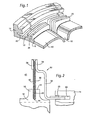
- Figure 1 illustrates a pair of adjacent transition pieces 10 and 12 and an annular interface forming part of a first-stage nozzle 14. It will be appreciated that there are a plurality of transition pieces arranged in an annular array thereof in communication with combustors for the gas turbine whereby the hot gases of combustion flow from the combustors through the transition pieces into the first-stage nozzle. The exit ends of the transition pieces are generally rectilinear passages for flowing the hot gases of combustion into the first-stage nozzle.
- the transition pieces typically have a surrounding pair of flanges 16 and 18 defining a slot 20 therebetween.
- slot 20 of each transition piece for example, transition pieces 10 and 12 extends outwardly about side walls of the transition pieces generally perpendicularly to the flow of the hot combustion gases.
- the opposing slots of the adjacent transition pieces register laterally one with the other.
- the annular interface of first-stage nozzle 14 has a generally annular slot 22 opening toward the combustor, i.e., in a generally axial direction relative to flow of the hot gases.
- Seal assemblies are typically provided between the transition pieces and the first-stage nozzle, with opposite edges of the seal assemblies residing in respective slots 20 and 22.
- FIG. 2 illustrates a seal assembly 30, constructed in accordance with a preferred embodiment of the invention, extending between respective slots 20 and 22 of transition piece 10 and first-stage nozzle 14.
- Seal assembly 30 includes a generally arcuate extending bracket 32 bent at one end forming a edge 33 for reception in slot 22 of first-stage nozzle 14.
- the opposite edge 34 of bracket 32 extends generally perpendicularly to the flow of gases through the transition piece and overlies, and is secured to, the outer edge of a metallic cloth 36.
- Cloth 36 is preferably a woven or knitted metallic cloth.
- a retaining strip 38 is provided along the opposite side of metallic cloth 36 from bracket edge 34 and the outer edge of cloth 36 is sandwiched between and secured for example, by welding, to bracket edge 34 and retaining strip 38.
- Metallic cloth 36 depends from bracket 32 into slot 20 of transition piece 10.
- Metallic cloth 36 may comprise a single layer and preferably comprises a pair of layers folded one over the other, the fold line appearing along the lower edge of the cloth in slot 20.
- the cloth may comprise a high temperature-resistant material, such as metal, ceramic or polymer fibers which have been woven, knitted or pressed into a layer of fabric. If there are two layers of cloth, the multiple cloth layers may comprise different materials, a different layer construction or have different thicknesses, depending upon particular seal applications.
- a Dutch twill weave cloth assemblage formed of a high temperature cobalt-based superalloy, such as L-605 or Hanes-25 may be utilized.
- a stiff high temperature-resistant shim 42 is provided in the form of sheet material.
- the shim extends along the surface of metallic cloth 36 on the high pressure side and into slot 20 of the transition piece.
- lower edge 44 of shim 42 is extended or bent over lower edge 45 of metallic cloth 36 and extended to the sealing surface of slot 20, i.e., the face of flange 18, engaged by cloth 36 to provide enhanced flow resistance in addition to the resistance to flow afforded by the cloth.
- any flow from high pressure region 40 around the lower edge of cloth 36 to a lower pressure region on the opposite side of the seal assembly is choked, i.e., precluded or minimized.
- added flow resistance on top of the resistance offered by the filtering cloth material is provided.
- Shim 42 preferably comprises at least one layer but may comprise two superimposed identical layers of shim having staggered seams for added flexibility.
- Each shim layer may comprise a metal, ceramic or polymer sheet.
- a shim layer may comprise a high temperature cobalt-based superalloy such as Inconel-750 or HS-188.
- the shim layers can comprise different materials and/or have different thicknesses, depending upon the particular seal application.
- seal assemblies 30 are provided about the annular array of transition pieces to accommodate relative movement of the transition pieces and the first-stage nozzle.
- the adjacent seal assemblies may abut one another in side-by-side relation.
- Spline seals are employed to seal between the opposed lateral edges of the transition pieces as well as to overlie the abutting surfaces of seal assemblies 30.
- a spline seal 50 generally comprises an elongated member 52, as illustrated in Figure 5 , formed of a folded-over metallic cloth 56 and an elongate shim 58, as shown in Figure 6 .
- the metallic cloth and the shim of the elongated spline seals are formed of the same materials as the corresponding parts of seal assemblies 30 sealing between the transition pieces and the first-stage nozzle.
- the lateral edges 60 of each shim 58 overlie the lateral edges of metallic cloth 56 and extend to the sealing surfaces of the slots engaged by the exposed face of cloth 56.
- each shim 58 choke any leakage flow from the high-pressure region past the long edges of each shim into the filtering cloth material and beyond.
- each spline seal 50 extends along the joint between adjacent seal assemblies 30.
- the strip 38 of each adjacent seal assembly 30 extends short of the lateral edge of the seal assembly 30 to accommodate the spline seal assembly 30 in final assembly.
- the bent tabs 64 of spline seals 50 are secured to the first-stage nozzle interface.
Landscapes
- Engineering & Computer Science (AREA)
- General Engineering & Computer Science (AREA)
- Mechanical Engineering (AREA)
- Turbine Rotor Nozzle Sealing (AREA)
Applications Claiming Priority (2)
| Application Number | Priority Date | Filing Date | Title |
|---|---|---|---|
| US798842 | 1985-11-20 | ||
| US09/798,842 US20020121744A1 (en) | 2001-03-05 | 2001-03-05 | Low leakage flexible cloth seals for turbine combustors |
Publications (3)
| Publication Number | Publication Date |
|---|---|
| EP1239118A2 EP1239118A2 (en) | 2002-09-11 |
| EP1239118A3 EP1239118A3 (en) | 2004-09-08 |
| EP1239118B1 true EP1239118B1 (en) | 2010-05-26 |
Family
ID=25174413
Family Applications (1)
| Application Number | Title | Priority Date | Filing Date |
|---|---|---|---|
| EP02251538A Expired - Lifetime EP1239118B1 (en) | 2001-03-05 | 2002-03-05 | Flexible cloth seal for turbine combustors |
Country Status (4)
| Country | Link |
|---|---|
| US (1) | US20020121744A1 (https=) |
| EP (1) | EP1239118B1 (https=) |
| JP (1) | JP4020661B2 (https=) |
| DE (1) | DE60236475D1 (https=) |
Families Citing this family (44)
| Publication number | Priority date | Publication date | Assignee | Title |
|---|---|---|---|---|
| US6733234B2 (en) * | 2002-09-13 | 2004-05-11 | Siemens Westinghouse Power Corporation | Biased wear resistant turbine seal assembly |
| US7788932B2 (en) | 2005-08-23 | 2010-09-07 | Mitsubishi Heavy Industries, Ltd. | Seal structure for gas turbine combustor |
| US7600970B2 (en) * | 2005-12-08 | 2009-10-13 | General Electric Company | Ceramic matrix composite vane seals |
| JP4747146B2 (ja) * | 2007-09-27 | 2011-08-17 | 株式会社日立製作所 | ガスタービンのシール装置 |
| US8151570B2 (en) * | 2007-12-06 | 2012-04-10 | Alstom Technology Ltd | Transition duct cooling feed tubes |
| EP2247830B1 (en) | 2008-02-27 | 2019-04-10 | General Electric Company | Flexible seal for a turbine and corresponding turbine |
| US8141879B2 (en) * | 2009-07-20 | 2012-03-27 | General Electric Company | Seals for a turbine engine, and methods of assembling a turbine engine |
| US8491259B2 (en) * | 2009-08-26 | 2013-07-23 | Siemens Energy, Inc. | Seal system between transition duct exit section and turbine inlet in a gas turbine engine |
| US8511972B2 (en) * | 2009-12-16 | 2013-08-20 | Siemens Energy, Inc. | Seal member for use in a seal system between a transition duct exit section and a turbine inlet in a gas turbine engine |
| US8398090B2 (en) * | 2010-06-09 | 2013-03-19 | General Electric Company | Spring loaded seal assembly for turbines |
| US8225614B2 (en) * | 2010-10-07 | 2012-07-24 | General Electric Company | Shim for sealing transition pieces |
| US9121279B2 (en) * | 2010-10-08 | 2015-09-01 | Alstom Technology Ltd | Tunable transition duct side seals in a gas turbine engine |
| US20120119447A1 (en) * | 2010-11-11 | 2012-05-17 | General Electric Company | Transition Piece Sealing Assembly |
| US8613451B2 (en) * | 2010-11-29 | 2013-12-24 | General Electric Company | Cloth seal for turbo-machinery |
| US20120183393A1 (en) * | 2011-01-14 | 2012-07-19 | General Electric Company | Assembly and method for preventing fluid flow |
| US8777202B2 (en) * | 2011-05-19 | 2014-07-15 | General Electric Company | Tool for adjusting seal |
| US9879555B2 (en) | 2011-05-20 | 2018-01-30 | Siemens Energy, Inc. | Turbine combustion system transition seals |
| US8562000B2 (en) | 2011-05-20 | 2013-10-22 | Siemens Energy, Inc. | Turbine combustion system transition piece side seals |
| US9115585B2 (en) * | 2011-06-06 | 2015-08-25 | General Electric Company | Seal assembly for gas turbine |
| US8888445B2 (en) | 2011-08-19 | 2014-11-18 | General Electric Company | Turbomachine seal assembly |
| US9938844B2 (en) | 2011-10-26 | 2018-04-10 | General Electric Company | Metallic stator seal |
| US9188228B2 (en) * | 2011-10-26 | 2015-11-17 | General Electric Company | Layered seal for turbomachinery |
| US8701415B2 (en) * | 2011-11-09 | 2014-04-22 | General Electric Company | Flexible metallic seal for transition duct in turbine system |
| US10161523B2 (en) | 2011-12-23 | 2018-12-25 | General Electric Company | Enhanced cloth seal |
| US9341120B2 (en) | 2012-02-10 | 2016-05-17 | United Technologies Corporation | Channeled spring seal for sealing an air gap between moving plates |
| US9115808B2 (en) * | 2012-02-13 | 2015-08-25 | General Electric Company | Transition piece seal assembly for a turbomachine |
| US20130283817A1 (en) * | 2012-04-30 | 2013-10-31 | General Electric Company | Flexible seal for transition duct in turbine system |
| US9670791B2 (en) | 2013-03-04 | 2017-06-06 | United Technologies Corporation | Flexible finger seal for sealing a gap between turbine engine components |
| US9366444B2 (en) | 2013-11-12 | 2016-06-14 | Siemens Energy, Inc. | Flexible component providing sealing connection |
| US10047622B2 (en) * | 2014-07-22 | 2018-08-14 | General Electric Company | Flexible layered seal for turbomachinery |
| WO2016068857A1 (en) | 2014-10-28 | 2016-05-06 | Siemens Aktiengesellschaft | Seal assembly between a transition duct and the first row vane assembly for use in turbine engines |
| US20160215701A1 (en) * | 2015-01-22 | 2016-07-28 | General Electric Company | Inner seal for a turbomachine transition piece frame assembly |
| US10036267B2 (en) * | 2015-11-24 | 2018-07-31 | General Electric Company | System of supporting turbine diffuser outlet |
| US10323751B2 (en) | 2015-12-04 | 2019-06-18 | General Electric Company | Seal assembly for a submersible pumping system and an associated method thereof |
| JP6767493B2 (ja) * | 2016-01-27 | 2020-10-14 | シーメンス アクティエンゲゼルシャフト | ガスタービンエンジンのための移行システムのサイドシール |
| US10689995B2 (en) * | 2016-05-27 | 2020-06-23 | General Electric Company | Side seal with reduced corner leakage |
| GB201614711D0 (en) * | 2016-08-31 | 2016-10-12 | Rolls Royce Plc | Axial flow machine |
| US10508602B2 (en) * | 2016-09-01 | 2019-12-17 | General Electric Company | Corner flow reduction seals |
| US10690059B2 (en) * | 2016-09-26 | 2020-06-23 | General Electric Company | Advanced seals with reduced corner leakage |
| US10890078B1 (en) * | 2017-06-12 | 2021-01-12 | Technetics Group Llc | Flexible seal assembly |
| US10655489B2 (en) | 2018-01-04 | 2020-05-19 | General Electric Company | Systems and methods for assembling flow path components |
| JP6966354B2 (ja) * | 2018-02-28 | 2021-11-17 | 三菱パワー株式会社 | ガスタービン燃焼器 |
| DE102019108267A1 (de) * | 2019-03-29 | 2020-10-01 | Rolls-Royce Deutschland Ltd & Co Kg | Vorrichtung zur Befestigung von Dichtplatten zwischen Bauteilen eines Gasturbinentriebwerks |
| DE102022207874A1 (de) | 2022-07-29 | 2024-02-01 | Siemens Energy Global GmbH & Co. KG | Dichtsegment mit Lasche und Tasche |
Family Cites Families (9)
| Publication number | Priority date | Publication date | Assignee | Title |
|---|---|---|---|---|
| US158738A (en) | 1875-01-12 | Improvement in seats for extension-carriages | ||
| US4645217A (en) * | 1985-11-29 | 1987-02-24 | United Technologies Corporation | Finger seal assembly |
| US5568931A (en) * | 1992-08-20 | 1996-10-29 | General Electric Company | Brush seal |
| US5474306A (en) | 1992-11-19 | 1995-12-12 | General Electric Co. | Woven seal and hybrid cloth-brush seals for turbine applications |
| US5657998A (en) | 1994-09-19 | 1997-08-19 | General Electric Company | Gas-path leakage seal for a gas turbine |
| DE19529655C2 (de) * | 1995-08-11 | 1999-04-22 | Mtu Muenchen Gmbh | Bürstendichtung für Turbomaschinen |
| ATE238509T1 (de) * | 1995-10-05 | 2003-05-15 | Sealol | Bürstendichtung mit einer biegsamen frontscheibe |
| US5915697A (en) | 1997-09-22 | 1999-06-29 | General Electric Company | Flexible cloth seal assembly |
| EP1052438A3 (en) * | 1999-05-13 | 2002-02-06 | General Electric Company | Brush seal segment with bristle damping |
-
2001
- 2001-03-05 US US09/798,842 patent/US20020121744A1/en not_active Abandoned
-
2002
- 2002-03-04 JP JP2002056696A patent/JP4020661B2/ja not_active Expired - Fee Related
- 2002-03-05 DE DE60236475T patent/DE60236475D1/de not_active Expired - Lifetime
- 2002-03-05 EP EP02251538A patent/EP1239118B1/en not_active Expired - Lifetime
Also Published As
| Publication number | Publication date |
|---|---|
| US20020121744A1 (en) | 2002-09-05 |
| DE60236475D1 (de) | 2010-07-08 |
| JP2002339706A (ja) | 2002-11-27 |
| EP1239118A2 (en) | 2002-09-11 |
| EP1239118A3 (en) | 2004-09-08 |
| JP4020661B2 (ja) | 2007-12-12 |
Similar Documents
| Publication | Publication Date | Title |
|---|---|---|
| EP1239118B1 (en) | Flexible cloth seal for turbine combustors | |
| US20030039542A1 (en) | Transition piece side sealing element and turbine assembly containing such seal | |
| US5934687A (en) | Gas-path leakage seal for a turbine | |
| EP3327254B1 (en) | Seal assembly for gas turbine engine components | |
| KR100762535B1 (ko) | 터빈 | |
| US6503051B2 (en) | Overlapping interference seal and methods for forming the seal | |
| EP0903519A1 (en) | Flexible cloth seal assembly | |
| EP1323898B1 (en) | Supplemental seal for the chordal hinge seal in a gas turbine | |
| EP1323896B1 (en) | Turbine with a static seal | |
| US10731494B2 (en) | Overhanging seal assembly for a gas turbine | |
| GB2335470A (en) | A longitudinal seal for jet pipe liner panels | |
| US7220099B2 (en) | Sealing arrangement for a rotor of a turbo machine | |
| EP2247830B1 (en) | Flexible seal for a turbine and corresponding turbine | |
| US9188228B2 (en) | Layered seal for turbomachinery | |
| CA2580327C (en) | Fuel conveying member with side-brazed sealing members | |
| WO2006091325A1 (en) | Cooled transition duct for a gas turbine engine | |
| EP0911490B1 (en) | Double cross type seal device for stationary gas turbine blades | |
| JP2003113945A (ja) | 軸シール機構及びタービン | |
| EP1323890B1 (en) | Turbine with a supplemental seal for the chordal hinge seal | |
| GB2267319A (en) | Sealing components in turbine engines. | |
| US5941070A (en) | Flexible sealed conduit system | |
| US20030122321A1 (en) | Supplemental seal for the chordal hinge seals in a gas turbine | |
| EP1387042B1 (en) | Steam turbine packing casing horizontal joint seals and methods of forming the seals | |
| US20040175263A1 (en) | Method and apparatus for rotating machine main fit seal | |
| CH711014A2 (de) | Dichtungsanordnung mit einer Wärmesperre für Turbomaschinen. |
Legal Events
| Date | Code | Title | Description |
|---|---|---|---|
| PUAI | Public reference made under article 153(3) epc to a published international application that has entered the european phase |
Free format text: ORIGINAL CODE: 0009012 |
|
| AK | Designated contracting states |
Kind code of ref document: A2 Designated state(s): AT BE CH CY DE DK ES FI FR GB GR IE IT LI LU MC NL PT SE TR |
|
| AX | Request for extension of the european patent |
Free format text: AL;LT;LV;MK;RO;SI |
|
| PUAL | Search report despatched |
Free format text: ORIGINAL CODE: 0009013 |
|
| AK | Designated contracting states |
Kind code of ref document: A3 Designated state(s): AT BE CH CY DE DK ES FI FR GB GR IE IT LI LU MC NL PT SE TR |
|
| AX | Request for extension of the european patent |
Extension state: AL LT LV MK RO SI |
|
| RIC1 | Information provided on ipc code assigned before grant |
Ipc: 7F 16J 15/32 B Ipc: 7F 01D 11/00 A |
|
| 17P | Request for examination filed |
Effective date: 20050308 |
|
| AKX | Designation fees paid |
Designated state(s): CH DE FR GB IT LI |
|
| 17Q | First examination report despatched |
Effective date: 20070625 |
|
| GRAP | Despatch of communication of intention to grant a patent |
Free format text: ORIGINAL CODE: EPIDOSNIGR1 |
|
| RIN1 | Information on inventor provided before grant (corrected) |
Inventor name: BAGEPALLI, BHARAT SAMPATHKUMAR Inventor name: BLAND, ROBERT JAMES LLOYD Inventor name: ASLAM, SAMI Inventor name: EBNOIT, JEFFREY ARTHUR Inventor name: AKSIT, MAHMUT FARUK |
|
| GRAS | Grant fee paid |
Free format text: ORIGINAL CODE: EPIDOSNIGR3 |
|
| GRAA | (expected) grant |
Free format text: ORIGINAL CODE: 0009210 |
|
| AK | Designated contracting states |
Kind code of ref document: B1 Designated state(s): CH DE FR GB IT LI |
|
| REG | Reference to a national code |
Ref country code: GB Ref legal event code: FG4D |
|
| REG | Reference to a national code |
Ref country code: CH Ref legal event code: NV Representative=s name: SERVOPATENT GMBH Ref country code: CH Ref legal event code: EP |
|
| REF | Corresponds to: |
Ref document number: 60236475 Country of ref document: DE Date of ref document: 20100708 Kind code of ref document: P |
|
| PLBE | No opposition filed within time limit |
Free format text: ORIGINAL CODE: 0009261 |
|
| STAA | Information on the status of an ep patent application or granted ep patent |
Free format text: STATUS: NO OPPOSITION FILED WITHIN TIME LIMIT |
|
| 26N | No opposition filed |
Effective date: 20110301 |
|
| REG | Reference to a national code |
Ref country code: DE Ref legal event code: R097 Ref document number: 60236475 Country of ref document: DE Effective date: 20110228 |
|
| REG | Reference to a national code |
Ref country code: CH Ref legal event code: PL |
|
| GBPC | Gb: european patent ceased through non-payment of renewal fee |
Effective date: 20110305 |
|
| REG | Reference to a national code |
Ref country code: FR Ref legal event code: ST Effective date: 20111130 |
|
| PG25 | Lapsed in a contracting state [announced via postgrant information from national office to epo] |
Ref country code: CH Free format text: LAPSE BECAUSE OF NON-PAYMENT OF DUE FEES Effective date: 20110331 Ref country code: FR Free format text: LAPSE BECAUSE OF NON-PAYMENT OF DUE FEES Effective date: 20110331 Ref country code: LI Free format text: LAPSE BECAUSE OF NON-PAYMENT OF DUE FEES Effective date: 20110331 Ref country code: DE Free format text: LAPSE BECAUSE OF NON-PAYMENT OF DUE FEES Effective date: 20111001 |
|
| REG | Reference to a national code |
Ref country code: DE Ref legal event code: R119 Ref document number: 60236475 Country of ref document: DE Effective date: 20111001 |
|
| PG25 | Lapsed in a contracting state [announced via postgrant information from national office to epo] |
Ref country code: GB Free format text: LAPSE BECAUSE OF NON-PAYMENT OF DUE FEES Effective date: 20110305 Ref country code: IT Free format text: LAPSE BECAUSE OF NON-PAYMENT OF DUE FEES Effective date: 20110305 |