EP1764481A2 - Stator vane with ceramic airfoil and metallic platforms - Google Patents
Stator vane with ceramic airfoil and metallic platforms Download PDFInfo
- Publication number
- EP1764481A2 EP1764481A2 EP06254486A EP06254486A EP1764481A2 EP 1764481 A2 EP1764481 A2 EP 1764481A2 EP 06254486 A EP06254486 A EP 06254486A EP 06254486 A EP06254486 A EP 06254486A EP 1764481 A2 EP1764481 A2 EP 1764481A2
- Authority
- EP
- European Patent Office
- Prior art keywords
- airfoil
- stator vane
- interface
- platforms
- vane assembly
- Prior art date
- Legal status (The legal status is an assumption and is not a legal conclusion. Google has not performed a legal analysis and makes no representation as to the accuracy of the status listed.)
- Withdrawn
Links
Images

Classifications
-
- F—MECHANICAL ENGINEERING; LIGHTING; HEATING; WEAPONS; BLASTING
- F01—MACHINES OR ENGINES IN GENERAL; ENGINE PLANTS IN GENERAL; STEAM ENGINES
- F01D—NON-POSITIVE DISPLACEMENT MACHINES OR ENGINES, e.g. STEAM TURBINES
- F01D11/00—Preventing or minimising internal leakage of working-fluid, e.g. between stages
- F01D11/08—Preventing or minimising internal leakage of working-fluid, e.g. between stages for sealing space between rotor blade tips and stator
-
- F—MECHANICAL ENGINEERING; LIGHTING; HEATING; WEAPONS; BLASTING
- F01—MACHINES OR ENGINES IN GENERAL; ENGINE PLANTS IN GENERAL; STEAM ENGINES
- F01D—NON-POSITIVE DISPLACEMENT MACHINES OR ENGINES, e.g. STEAM TURBINES
- F01D9/00—Stators
- F01D9/02—Nozzles; Nozzle boxes; Stator blades; Guide conduits, e.g. individual nozzles
- F01D9/04—Nozzles; Nozzle boxes; Stator blades; Guide conduits, e.g. individual nozzles forming ring or sector
- F01D9/042—Nozzles; Nozzle boxes; Stator blades; Guide conduits, e.g. individual nozzles forming ring or sector fixing blades to stators
-
- F—MECHANICAL ENGINEERING; LIGHTING; HEATING; WEAPONS; BLASTING
- F01—MACHINES OR ENGINES IN GENERAL; ENGINE PLANTS IN GENERAL; STEAM ENGINES
- F01D—NON-POSITIVE DISPLACEMENT MACHINES OR ENGINES, e.g. STEAM TURBINES
- F01D11/00—Preventing or minimising internal leakage of working-fluid, e.g. between stages
- F01D11/005—Sealing means between non relatively rotating elements
-
- F—MECHANICAL ENGINEERING; LIGHTING; HEATING; WEAPONS; BLASTING
- F01—MACHINES OR ENGINES IN GENERAL; ENGINE PLANTS IN GENERAL; STEAM ENGINES
- F01D—NON-POSITIVE DISPLACEMENT MACHINES OR ENGINES, e.g. STEAM TURBINES
- F01D5/00—Blades; Blade-carrying members; Heating, heat-insulating, cooling or antivibration means on the blades or the members
- F01D5/12—Blades
- F01D5/14—Form or construction
- F01D5/147—Construction, i.e. structural features, e.g. of weight-saving hollow blades
-
- F—MECHANICAL ENGINEERING; LIGHTING; HEATING; WEAPONS; BLASTING
- F01—MACHINES OR ENGINES IN GENERAL; ENGINE PLANTS IN GENERAL; STEAM ENGINES
- F01D—NON-POSITIVE DISPLACEMENT MACHINES OR ENGINES, e.g. STEAM TURBINES
- F01D5/00—Blades; Blade-carrying members; Heating, heat-insulating, cooling or antivibration means on the blades or the members
- F01D5/12—Blades
- F01D5/28—Selecting particular materials; Particular measures relating thereto; Measures against erosion or corrosion
- F01D5/284—Selection of ceramic materials
-
- F—MECHANICAL ENGINEERING; LIGHTING; HEATING; WEAPONS; BLASTING
- F01—MACHINES OR ENGINES IN GENERAL; ENGINE PLANTS IN GENERAL; STEAM ENGINES
- F01D—NON-POSITIVE DISPLACEMENT MACHINES OR ENGINES, e.g. STEAM TURBINES
- F01D9/00—Stators
- F01D9/02—Nozzles; Nozzle boxes; Stator blades; Guide conduits, e.g. individual nozzles
-
- F—MECHANICAL ENGINEERING; LIGHTING; HEATING; WEAPONS; BLASTING
- F05—INDEXING SCHEMES RELATING TO ENGINES OR PUMPS IN VARIOUS SUBCLASSES OF CLASSES F01-F04
- F05D—INDEXING SCHEME FOR ASPECTS RELATING TO NON-POSITIVE-DISPLACEMENT MACHINES OR ENGINES, GAS-TURBINES OR JET-PROPULSION PLANTS
- F05D2230/00—Manufacture
- F05D2230/60—Assembly methods
- F05D2230/64—Assembly methods using positioning or alignment devices for aligning or centring, e.g. pins
- F05D2230/642—Assembly methods using positioning or alignment devices for aligning or centring, e.g. pins using maintaining alignment while permitting differential dilatation
-
- F—MECHANICAL ENGINEERING; LIGHTING; HEATING; WEAPONS; BLASTING
- F05—INDEXING SCHEMES RELATING TO ENGINES OR PUMPS IN VARIOUS SUBCLASSES OF CLASSES F01-F04
- F05D—INDEXING SCHEME FOR ASPECTS RELATING TO NON-POSITIVE-DISPLACEMENT MACHINES OR ENGINES, GAS-TURBINES OR JET-PROPULSION PLANTS
- F05D2300/00—Materials; Properties thereof
- F05D2300/60—Properties or characteristics given to material by treatment or manufacturing
- F05D2300/603—Composites; e.g. fibre-reinforced
- F05D2300/6033—Ceramic matrix composites [CMC]
Abstract
Description
- This invention relates generally to turbine nozzle assemblies and specifically, to platform interface configurations for stage 2 CMC nozzle vanes.
- Sealing between high temperature components such as ceramic matrix composite (CMC) nozzle vanes and radially inner and outer metallic attachments or platforms problems relating to steep thermal gradients with associated high thermal stresses and reduced component life; internal pressure due to cooling air resulting in air flow wall distortion; and time varying performance erosion due to historical seal degradation. Eliminating the seal between a CMC vane and metal inner and outer platforms, however, results in an open channel for hot gas ingestion. Accordingly, there remains a need for a new geometry at the interface of the CMC vane and either one or both of the radially inner and outer metallic platforms that accommodates the inherent difficulties in the matching of ceramic and metal components, and that also eliminates the need for separate and discrete sealing elements. Seai-less design is also synonymous with unpressurized vane design.
- Controlled leakage is the key to the success of a seal-less design. Controlled leakage can be accommodated by creative interface configurations on the platform interface surface, the vane interface surface, or both. In the exemplary embodiments of this invention, creative interface configurations are provided that establish a circuitous gas leak path for increased flow resistance, resulting in the desired controlled leakage.
- In the various embodiments described herein, a CMC stator vane (also referred to herein as an airfoil shell or, simply airfoil) is assembled between a pair of radially inner and outer metal platforms that may be radially interconnected by a pair of spars extending through the airfoil shell. Each of the platforms is formed on its interior face with an airfoil-shaped recess adapted to receive the CMC airfoil shell. The seal-less configurations described herein are located on the airfoil shell and/or on adjacent interior peripheral surfaces of the airfoil-shaped recesses on the inner and/or outer platforms.
- In one exemplary embodiment, mating step joints are formed on the peripheral surface of each platform recess and the respective adjacent airfoil shell surfaces.
- In a second exemplary embodiment, the interface configuration is in the form of a scarf joint, i.e., with mating angled surfaces extending about the adjacent peripheries of each platform recess and respective airfoil shell surface.
- In a third exemplary embodiment, the platform airfoil surfaces are formed with a plurality of laterally projecting, abradable knife edges that interface with adjacent smooth surfaces on the airfoil shell.
- In a fourth exemplary embodiment, a compliant or spring interface is provided on the peripheral surface of each platform recess for engagement with a respective smooth surface on the adjacent airfoil shell. It will be appreciated that the free end or edge surface of the compliant interface may also be formed with a step joint or scarf joint as described above, to interface with the adjacent mating surface on the respective airfoil shell to provide the desired circuitous or tortuous path.
- Accordingly, in one aspect, the present invention relates to a stator vane assembly for a gas turbine comprising a ceramic matrix composite airfoil held between radially inner and outer metal platforms wherein an interface between the airfoil and at least one of the radially inner and outer platforms is shaped to create a circuitous leakage path for gas from the gas turbine hot gas path.
- In another aspect, the invention relates to a stator vane assembly for a gas turbine comprising a ceramic matrix composite airfoil held between radially inner and outer metal platforms wherein each of the platforms is formed with a recess adapted to receive the inner and outer platforms, each recess including a peripheral edge, the peripheral edge shaped to create the circuitous leakage path in cooperation with an adjacent surface on the airfoil.
- In still another aspect, the invention relates to a stator vane assembly for a gas turbine comprising a ceramic matrix composite vane held between radially inner and outer metal platforms wherein an interface between the vane and at least one of the radially inner and outer platforms is shaped to provide a compliant face for engagement with a smooth surface on the vane.
- The invention will now be described in greater detail, by way of example, with reference to the drawings, in which:-
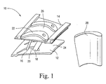
- FIGURE 1 is a perspective exploded view of a CMC airfoil shell and associated inner and outer metal platforms connected by radial spars;
- FIGURE 2 is a schematic of a baseline or reference configuration at the interface of a CMC airfoil shell and a radially inner metal platform;
- FIGURE 3 is a schematic of a step joint interface between a CMC airfoil shell and an inner metal platform in accordance with a first exemplary embodiment of the invention;
- FIGURE 4 is a schematic of a scarf joint interface between a CMC airfoil shell and an inner metal platform in accordance with a second exemplary embodiment of the invention;
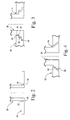
- FIGURE 5 is a schematic of an abradable knife edge interface between a CMC airfoil shell and an inner metal platform in accordance with a third exemplary embodiment of the invention;
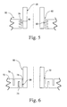
- FIGURE 6 is a schematic illustrating a compliant interface between a CMC airfoil shell and an inner metal platform in accordance with a fourth exemplary embodiment of the invention;
- FIGURE 7 is a schematic of a combined compliant/step joint interface between a CMC airfoil shell and an inner metal platform in accordance with a fourth exemplary embodiment of the invention; and
- FIGURE 8 is a schematic of a combined compliant scarf joint interface between a CMC airfoil shell and an inner metal platform in accordance with a fifth exemplary embodiment of the invention.
- With reference to Figure 1, a CMC airfoil shell and
metal platform assembly 10 is shown in exploded form. More specifically, a pair of radially inner andouter metal platforms radial spars shaped recesses metal platform surfaces larger spar 18 is in the shape of a hollow channel that supplies cooling air to theairfoil shell 28. In this regard, theairfoil shell 28 is a hollow member that can be slidably received over the spars during assembly, with opposite ends of the airfoil shell received in therecesses platforms - In an alternative arrangement, the
spars external airfoil shell 28 in telescoping relationship, with appropriate dimensional tolerances. - As illustrated in Figure 1, the
recesses airfoil shell 28. It will be appreciated that the tolerances between the airfoil shell and the platform recesses must be controlled to avoid harmful excessive vibration, but at the same time, avoid problems associated with thermal mismatch between the components. - Turning to Figure 2, the
airfoil shell 28 is schematically represented as seated in the airfoil-shaped recess 20 of theinner metal platform 24. Therecess 20 is defined by the closedperipheral edge 30 that interfaces withsurfaces airfoil shell 28. This illustration provides a baseline reference for the interface configurations described below. In this regard, the unique interface configurations described herein are formed at the interface betweenrecess surface 30 and opposedsurfaces inner platform 24, and/or at the radiallyouter platform 14. For convenience, only the interfaces at the radially inner platforms are shown. - With reference now to Figure 3, the
CMC airfoil shell 36 is shown in assembled relationship with aninner metal platform 38. In this example, the interface configuration (or simply interface) is in the form of a step joint, with laterallyoriented steps peripheral edge 43 of the lower platform recess 44 engaged withlateral shoulders airfoil shell 36. Note that this arrangement allows the insertion of the airfoil shell from below thelower platform 38. The step joint at the opposite end of the airfoil shell would be reversed, however, to permit one-way installation of theshell 36 between both the inner and outer platforms. With appropriate tolerances between the interfacing surfaces, it will be appreciated that any gas leaking out of the hot gas path of the turbine, will necessarily be forced to follow a circuitous route through the interface, establishing the desirable controlled leakage, and without having to use discrete sealing elements. - With reference now to Figure 4, another interface is illustrated that is of simpler design than the configuration in Figure 3. Specifically, a
CMC airfoil shell 50 is shown in assembled relationship with respect to aninner metal platform 52. In this embodiment, the radiallyinner platform recess 54 is formed with aperipheral edge surface 56 that is slanted at about a 45° angle to a radial centerline through theairfoil shell 50. At the same time, thelower surface 58 of theairfoil shell 50 is formed at a similar angle, thus forming a scarf joint between the airfoil shell and theinner platform 52. Here again, for purposes of facilitating one-way installation, the interface at the upper end of the airfoil shell would be reversed. - In Figure 5, yet another embodiment is shown where a
CMC airfoil shell 58 is seated within therecess 62 in theinner metal platform 60. In this embodiment, therecess 62 in theplatform 60 is formed with aperipheral edge 63 made up of a plurality of inwardly projecting abradable knife edges 64 (four shown), spaced from each other in the radial direction. Theedges 64 interface with an adjacentsmooth surface 66 on theairfoil shell 58, with appropriate tolerance between the two. Here again, it will be appreciated that resistance to leakage gas is increased by reason of the circuitous path through the platform. - In Figure 6, a compliant interface is provided between a
CMC airfoil shell 68 and aninner metal platform 70. In this embodiment, therecess 72 in the inner platform is formed with a peripheral edge having oppositely directed cutouts orslots edge 80 of therecess 72 to act in the nature of a spring, in compliant or resilient "engagement" (i.e., with minimal clearance) with an adjacentsmooth surface 78 of the airfoil shell. In order to incorporate the circuitous leakage gas feature of the earlier-described embodiments, it will be appreciated that theedge 80 of theplatform recess 72 may be configured to incorporate a step joint as illustrated in Figure 3 or a scarf joint as illustrated in Figure 4. These alternative interface configurations are shown schematically in Figures 7 and 8, respectively. Specifically, Figure 7 shows a compliant step joint where theCMC airfoil shell 82 is seated within therecess 84 in aninner metal platform 86, with theedge 88 of the compliant recess (formed by slots 90) formed with astep joint 92 that interfaces with acomplementary step joint 94 on the airfoil shell. - In Figure 8, the
CMC airfoil shell 96 is seated within therecess 98 in aninner metal platform 100, with theedge 102 of the recess 84 (formed by slots 104) formed with anangled surface 106 that interfaces with a complementary angledperipheral surface 108 on theairfoil shell 96, thus forming a compliant scarf joint at the interface. - By providing increased flow resistance resulting in controlled leakage, it is possible to eliminate the steep thermal gradients and associated reduction in thermal stresses and increased component life; thinner wall sections of the CMC vane to the elimination of internal pressure due to cooling air; and robust consistent performance by eliminating seal degradation.
Claims (10)
- A stator vane assembly for a gas turbine comprising a ceramic matrix composite airfoil (36) held between radially inner and outer metal platforms (38, 14) wherein an interface between said airfoil and at least one of said radially inner and outer platforms is shaped to create a circuitous leakage path for gas from the gas turbine.
- The stator vane assembly of claim 1 wherein said interface comprises mating stepped surfaces (40, 42).
- The stator vane assembly of claim 1 wherein said interface comprises a mating scarf joint (56, 58).
- The stator vane assembly of claim 1 wherein said interface comprises plural abradable knife edges (64) on said radially inner platform adjacent a smooth surface (66) on said airfoil.
- The stator vane assembly of any one of claims 1 to 4 wherein said interface is located at said radially inner platform (38).
- The stator assembly of claim 5 wherein a second substantially identical interface is located at said radially outer platform (14).
- The stator vane assembly of claim 2 wherein said mating stepped surfaces (40, 42) include at least two steps perpendicular to a radial centerline through said vane.
- The stator vane assembly of claim 3 wherein said scarf joint includes mating surfaces (56, 58) at an angle of about 45° relative to a radial centerline through said vane.
- The stator vane assembly of claim 4 wherein said plural abradable knife edges (64) comprise at least four projections terminating in radial surfaces adjacent said smooth surface (66) on said airfoil.
- A stator vane assembly for a gas turbine comprising a ceramic matrix composite airfoil (16) held between radially inner and outer metal platforms (38, 14) wherein each of said platforms is formed with a recess adapted to receive said inner and outer platforms, each recess including a peripheral edge, said peripheral edge shaped to create said circuitous leakage path in cooperation with an adjacent surface on said airfoil.
Applications Claiming Priority (1)
| Application Number | Priority Date | Filing Date | Title |
|---|---|---|---|
| US11/228,251 US7329087B2 (en) | 2005-09-19 | 2005-09-19 | Seal-less CMC vane to platform interfaces |
Publications (2)
| Publication Number | Publication Date |
|---|---|
| EP1764481A2 true EP1764481A2 (en) | 2007-03-21 |
| EP1764481A3 EP1764481A3 (en) | 2008-12-17 |
Family
ID=37216171
Family Applications (1)
| Application Number | Title | Priority Date | Filing Date |
|---|---|---|---|
| EP06254486A Withdrawn EP1764481A3 (en) | 2005-09-19 | 2006-08-29 | Stator vane with ceramic airfoil and metallic platforms |
Country Status (5)
| Country | Link |
|---|---|
| US (1) | US7329087B2 (en) |
| EP (1) | EP1764481A3 (en) |
| JP (1) | JP2007085342A (en) |
| KR (1) | KR20070032612A (en) |
| CN (1) | CN1936277A (en) |
Cited By (36)
| Publication number | Priority date | Publication date | Assignee | Title |
|---|---|---|---|---|
| DE102011120691A1 (en) | 2010-12-21 | 2012-06-21 | Alstom Technology Ltd. | A built-up blade assembly for a gas turbine and method of operating such a blade assembly |
| WO2014037675A1 (en) * | 2012-09-10 | 2014-03-13 | Snecma | Method for manufacturing a casing, made of a composite material, for a gas-turbine engine and casing thus obtained |
| WO2014130147A1 (en) * | 2013-02-23 | 2014-08-28 | Jun Shi | Edge seal for gas turbine engine ceramic matrix composite component |
| WO2016068859A1 (en) * | 2014-10-28 | 2016-05-06 | Siemens Energy, Inc. | Modular turbine vane |
| EP3022406A4 (en) * | 2013-07-18 | 2016-08-31 | United Technologies Corp | Gas turbine engine ceramic component assembly attachment |
| US9816387B2 (en) | 2014-09-09 | 2017-11-14 | United Technologies Corporation | Attachment faces for clamped turbine stator of a gas turbine engine |
| US10107117B2 (en) | 2014-09-30 | 2018-10-23 | United Technologies Corporation | Airfoil assembly with spacer and tie-spar |
| US10309238B2 (en) | 2016-11-17 | 2019-06-04 | United Technologies Corporation | Turbine engine component with geometrically segmented coating section and cooling passage |
| US10309226B2 (en) | 2016-11-17 | 2019-06-04 | United Technologies Corporation | Airfoil having panels |
| US10408082B2 (en) | 2016-11-17 | 2019-09-10 | United Technologies Corporation | Airfoil with retention pocket holding airfoil piece |
| US10408090B2 (en) | 2016-11-17 | 2019-09-10 | United Technologies Corporation | Gas turbine engine article with panel retained by preloaded compliant member |
| US10415407B2 (en) | 2016-11-17 | 2019-09-17 | United Technologies Corporation | Airfoil pieces secured with endwall section |
| US10428663B2 (en) | 2016-11-17 | 2019-10-01 | United Technologies Corporation | Airfoil with tie member and spring |
| US10428658B2 (en) | 2016-11-17 | 2019-10-01 | United Technologies Corporation | Airfoil with panel fastened to core structure |
| US10436062B2 (en) | 2016-11-17 | 2019-10-08 | United Technologies Corporation | Article having ceramic wall with flow turbulators |
| US10436049B2 (en) | 2016-11-17 | 2019-10-08 | United Technologies Corporation | Airfoil with dual profile leading end |
| US10458262B2 (en) | 2016-11-17 | 2019-10-29 | United Technologies Corporation | Airfoil with seal between endwall and airfoil section |
| CN110439629A (en) * | 2018-05-02 | 2019-11-12 | 通用电气公司 | With the CMC nozzle of interlocked mechanical connector and manufacture |
| US10480331B2 (en) | 2016-11-17 | 2019-11-19 | United Technologies Corporation | Airfoil having panel with geometrically segmented coating |
| US10480334B2 (en) | 2016-11-17 | 2019-11-19 | United Technologies Corporation | Airfoil with geometrically segmented coating section |
| US10502070B2 (en) | 2016-11-17 | 2019-12-10 | United Technologies Corporation | Airfoil with laterally insertable baffle |
| US10570765B2 (en) | 2016-11-17 | 2020-02-25 | United Technologies Corporation | Endwall arc segments with cover across joint |
| US10598025B2 (en) | 2016-11-17 | 2020-03-24 | United Technologies Corporation | Airfoil with rods adjacent a core structure |
| US10598029B2 (en) | 2016-11-17 | 2020-03-24 | United Technologies Corporation | Airfoil with panel and side edge cooling |
| US10605088B2 (en) | 2016-11-17 | 2020-03-31 | United Technologies Corporation | Airfoil endwall with partial integral airfoil wall |
| US10662782B2 (en) | 2016-11-17 | 2020-05-26 | Raytheon Technologies Corporation | Airfoil with airfoil piece having axial seal |
| US10662779B2 (en) | 2016-11-17 | 2020-05-26 | Raytheon Technologies Corporation | Gas turbine engine component with degradation cooling scheme |
| US10677091B2 (en) | 2016-11-17 | 2020-06-09 | Raytheon Technologies Corporation | Airfoil with sealed baffle |
| US10677079B2 (en) | 2016-11-17 | 2020-06-09 | Raytheon Technologies Corporation | Airfoil with ceramic airfoil piece having internal cooling circuit |
| US10711624B2 (en) | 2016-11-17 | 2020-07-14 | Raytheon Technologies Corporation | Airfoil with geometrically segmented coating section |
| US10711616B2 (en) | 2016-11-17 | 2020-07-14 | Raytheon Technologies Corporation | Airfoil having endwall panels |
| US10711794B2 (en) | 2016-11-17 | 2020-07-14 | Raytheon Technologies Corporation | Airfoil with geometrically segmented coating section having mechanical secondary bonding feature |
| US10731495B2 (en) | 2016-11-17 | 2020-08-04 | Raytheon Technologies Corporation | Airfoil with panel having perimeter seal |
| US10746038B2 (en) | 2016-11-17 | 2020-08-18 | Raytheon Technologies Corporation | Airfoil with airfoil piece having radial seal |
| US10767487B2 (en) | 2016-11-17 | 2020-09-08 | Raytheon Technologies Corporation | Airfoil with panel having flow guide |
| US10808554B2 (en) | 2016-11-17 | 2020-10-20 | Raytheon Technologies Corporation | Method for making ceramic turbine engine article |
Families Citing this family (40)
| Publication number | Priority date | Publication date | Assignee | Title |
|---|---|---|---|---|
| US7625170B2 (en) * | 2006-09-25 | 2009-12-01 | General Electric Company | CMC vane insulator and method of use |
| US7736131B1 (en) * | 2008-07-21 | 2010-06-15 | Florida Turbine Technologies, Inc. | Turbine blade with carbon nanotube shell |
| CH700001A1 (en) * | 2008-11-20 | 2010-05-31 | Alstom Technology Ltd | Moving blade arrangement, especially for a gas turbine. |
| US8382436B2 (en) * | 2009-01-06 | 2013-02-26 | General Electric Company | Non-integral turbine blade platforms and systems |
| US8262345B2 (en) * | 2009-02-06 | 2012-09-11 | General Electric Company | Ceramic matrix composite turbine engine |
| FR2945331B1 (en) * | 2009-05-07 | 2011-07-22 | Snecma | VIROLE FOR AIRCRAFT TURBOOMOTOR STATOR WITH MECHANICAL LOADING DUCKS OF AUBES. |
| EP2295722B1 (en) * | 2009-09-09 | 2019-11-06 | Ansaldo Energia IP UK Limited | Blade of a turbine |
| US8454303B2 (en) * | 2010-01-14 | 2013-06-04 | General Electric Company | Turbine nozzle assembly |
| US8727730B2 (en) * | 2010-04-06 | 2014-05-20 | General Electric Company | Composite turbine bucket assembly |
| US8939727B2 (en) | 2011-09-08 | 2015-01-27 | Siemens Energy, Inc. | Turbine blade and non-integral platform with pin attachment |
| CN102425667A (en) * | 2011-11-28 | 2012-04-25 | 北京动力机械研究所 | Seal assembly for air inlet passage special-shaped cavity |
| US9169736B2 (en) * | 2012-07-16 | 2015-10-27 | United Technologies Corporation | Joint between airfoil and shroud |
| CA2903730A1 (en) * | 2013-03-08 | 2014-09-12 | Rolls-Royce North American Technologies, Inc. | Method for forming a gas turbine engine composite airfoil assembly and corresponding airfoil assembly |
| EP2984292B1 (en) * | 2013-04-12 | 2018-06-06 | United Technologies Corporation | Stator vane platform with flanges |
| FR3006367B1 (en) * | 2013-05-28 | 2015-07-03 | Snecma | AUBE CREUSE, AND METHOD FOR MANUFACTURING THE SAME |
| DE102014205235A1 (en) * | 2014-03-20 | 2015-09-24 | Rolls-Royce Deutschland Ltd & Co Kg | Blade row group |
| US9926790B2 (en) | 2014-07-21 | 2018-03-27 | Rolls-Royce Corporation | Composite turbine components adapted for use with strip seals |
| EP2998517B1 (en) | 2014-09-16 | 2019-03-27 | Ansaldo Energia Switzerland AG | Sealing arrangement at the interface between a combustor and a turbine of a gas turbine and gas turbine with such a sealing arrangement |
| JP6614407B2 (en) | 2015-06-10 | 2019-12-04 | 株式会社Ihi | Turbine |
| US10450897B2 (en) | 2016-07-18 | 2019-10-22 | General Electric Company | Shroud for a gas turbine engine |
| US10378770B2 (en) | 2017-01-27 | 2019-08-13 | General Electric Company | Unitary flow path structure |
| US10393381B2 (en) | 2017-01-27 | 2019-08-27 | General Electric Company | Unitary flow path structure |
| US10816199B2 (en) | 2017-01-27 | 2020-10-27 | General Electric Company | Combustor heat shield and attachment features |
| US11111858B2 (en) | 2017-01-27 | 2021-09-07 | General Electric Company | Cool core gas turbine engine |
| US10371383B2 (en) | 2017-01-27 | 2019-08-06 | General Electric Company | Unitary flow path structure |
| US10253643B2 (en) | 2017-02-07 | 2019-04-09 | General Electric Company | Airfoil fluid curtain to mitigate or prevent flow path leakage |
| US10247019B2 (en) | 2017-02-23 | 2019-04-02 | General Electric Company | Methods and features for positioning a flow path inner boundary within a flow path assembly |
| US10385776B2 (en) | 2017-02-23 | 2019-08-20 | General Electric Company | Methods for assembling a unitary flow path structure |
| US10378373B2 (en) | 2017-02-23 | 2019-08-13 | General Electric Company | Flow path assembly with airfoils inserted through flow path boundary |
| US10385709B2 (en) | 2017-02-23 | 2019-08-20 | General Electric Company | Methods and features for positioning a flow path assembly within a gas turbine engine |
| US10253641B2 (en) | 2017-02-23 | 2019-04-09 | General Electric Company | Methods and assemblies for attaching airfoils within a flow path |
| US10370990B2 (en) | 2017-02-23 | 2019-08-06 | General Electric Company | Flow path assembly with pin supported nozzle airfoils |
| US10385731B2 (en) | 2017-06-12 | 2019-08-20 | General Electric Company | CTE matching hanger support for CMC structures |
| US10822973B2 (en) | 2017-11-28 | 2020-11-03 | General Electric Company | Shroud for a gas turbine engine |
| US11402097B2 (en) | 2018-01-03 | 2022-08-02 | General Electric Company | Combustor assembly for a turbine engine |
| US10934868B2 (en) | 2018-09-12 | 2021-03-02 | Rolls-Royce North American Technologies Inc. | Turbine vane assembly with variable position support |
| US10975706B2 (en) | 2019-01-17 | 2021-04-13 | Raytheon Technologies Corporation | Frustic load transmission feature for composite structures |
| US11268394B2 (en) | 2020-03-13 | 2022-03-08 | General Electric Company | Nozzle assembly with alternating inserted vanes for a turbine engine |
| US11536148B2 (en) * | 2020-11-24 | 2022-12-27 | Raytheon Technologies Corporation | Vane arc segment with thermal insulation element |
| US11428160B2 (en) | 2020-12-31 | 2022-08-30 | General Electric Company | Gas turbine engine with interdigitated turbine and gear assembly |
Citations (2)
| Publication number | Priority date | Publication date | Assignee | Title |
|---|---|---|---|---|
| US5634768A (en) | 1994-11-15 | 1997-06-03 | Solar Turbines Incorporated | Airfoil nozzle and shroud assembly |
| US6464456B2 (en) | 2001-03-07 | 2002-10-15 | General Electric Company | Turbine vane assembly including a low ductility vane |
Family Cites Families (13)
| Publication number | Priority date | Publication date | Assignee | Title |
|---|---|---|---|---|
| US3778184A (en) * | 1972-06-22 | 1973-12-11 | United Aircraft Corp | Vane damping |
| US3932056A (en) * | 1973-09-27 | 1976-01-13 | Barry Wright Corporation | Vane damping |
| DE2831547A1 (en) * | 1977-07-18 | 1979-02-01 | Norton Co | Turbine stator made of refractory or ceramic material - has blade free ends located by beading applied after assembly in part fired state |
| US4378961A (en) * | 1979-01-10 | 1983-04-05 | United Technologies Corporation | Case assembly for supporting stator vanes |
| GB2043798B (en) * | 1979-03-14 | 1983-01-12 | Rolls Royce | Gas turbine stator vane assembly |
| US4326835A (en) | 1979-10-29 | 1982-04-27 | General Motors Corporation | Blade platform seal for ceramic/metal rotor assembly |
| JPS59180006A (en) * | 1983-03-30 | 1984-10-12 | Hitachi Ltd | Gas turbine stator blade segment |
| JPS60209604A (en) * | 1984-04-04 | 1985-10-22 | Mitsubishi Heavy Ind Ltd | Gas turbine stationary blade |
| US5704762A (en) | 1993-11-08 | 1998-01-06 | Alliedsignal Inc. | Ceramic-to-metal stator vane assembly |
| US5630700A (en) * | 1996-04-26 | 1997-05-20 | General Electric Company | Floating vane turbine nozzle |
| US6000906A (en) * | 1997-09-12 | 1999-12-14 | Alliedsignal Inc. | Ceramic airfoil |
| US6409473B1 (en) * | 2000-06-27 | 2002-06-25 | Honeywell International, Inc. | Low stress connection methodology for thermally incompatible materials |
| US7052234B2 (en) * | 2004-06-23 | 2006-05-30 | General Electric Company | Turbine vane collar seal |
-
2005
- 2005-09-19 US US11/228,251 patent/US7329087B2/en active Active
-
2006
- 2006-08-29 EP EP06254486A patent/EP1764481A3/en not_active Withdrawn
- 2006-09-15 JP JP2006250272A patent/JP2007085342A/en active Pending
- 2006-09-18 KR KR1020060090238A patent/KR20070032612A/en not_active Application Discontinuation
- 2006-09-19 CN CNA2006101388236A patent/CN1936277A/en active Pending
Patent Citations (2)
| Publication number | Priority date | Publication date | Assignee | Title |
|---|---|---|---|---|
| US5634768A (en) | 1994-11-15 | 1997-06-03 | Solar Turbines Incorporated | Airfoil nozzle and shroud assembly |
| US6464456B2 (en) | 2001-03-07 | 2002-10-15 | General Electric Company | Turbine vane assembly including a low ductility vane |
Cited By (48)
| Publication number | Priority date | Publication date | Assignee | Title |
|---|---|---|---|---|
| US8998566B2 (en) | 2010-12-21 | 2015-04-07 | Alstom Technology Ltd. | Blade arrangement for a gas turbine and method for operating such a blade arrangement |
| DE102011120691A1 (en) | 2010-12-21 | 2012-06-21 | Alstom Technology Ltd. | A built-up blade assembly for a gas turbine and method of operating such a blade assembly |
| US9784122B2 (en) | 2012-09-10 | 2017-10-10 | Snecma | Method of fabricating a composite material casing for a gas turbine engine, and a casing obtained thereby |
| WO2014037675A1 (en) * | 2012-09-10 | 2014-03-13 | Snecma | Method for manufacturing a casing, made of a composite material, for a gas-turbine engine and casing thus obtained |
| FR2995344A1 (en) * | 2012-09-10 | 2014-03-14 | Snecma | METHOD FOR MANUFACTURING AN EXHAUST CASE OF COMPOSITE MATERIAL FOR A GAS TURBINE ENGINE AND AN EXHAUST CASE THUS OBTAINED |
| GB2519728B (en) * | 2012-09-10 | 2019-10-30 | Snecma | A method of fabricating a composite material casing for a gas turbine engine, and a casing obtained thereby |
| GB2519728A (en) * | 2012-09-10 | 2015-04-29 | Snecma | Method for manufacturing a casing, made of a composite material, for a gas-turbine engine and casing thus obtained |
| WO2014130147A1 (en) * | 2013-02-23 | 2014-08-28 | Jun Shi | Edge seal for gas turbine engine ceramic matrix composite component |
| US9080457B2 (en) | 2013-02-23 | 2015-07-14 | Rolls-Royce Corporation | Edge seal for gas turbine engine ceramic matrix composite component |
| EP3022406A4 (en) * | 2013-07-18 | 2016-08-31 | United Technologies Corp | Gas turbine engine ceramic component assembly attachment |
| US9816387B2 (en) | 2014-09-09 | 2017-11-14 | United Technologies Corporation | Attachment faces for clamped turbine stator of a gas turbine engine |
| US11041392B2 (en) | 2014-09-09 | 2021-06-22 | Raytheon Technologies Corporation | Attachment faces for clamped turbine stator of a gas turbine engine |
| US10107117B2 (en) | 2014-09-30 | 2018-10-23 | United Technologies Corporation | Airfoil assembly with spacer and tie-spar |
| US10465540B2 (en) | 2014-09-30 | 2019-11-05 | United Technologies Corporation | Airfoil assembly with spacer and tie-spar |
| WO2016068859A1 (en) * | 2014-10-28 | 2016-05-06 | Siemens Energy, Inc. | Modular turbine vane |
| US10711624B2 (en) | 2016-11-17 | 2020-07-14 | Raytheon Technologies Corporation | Airfoil with geometrically segmented coating section |
| US10746038B2 (en) | 2016-11-17 | 2020-08-18 | Raytheon Technologies Corporation | Airfoil with airfoil piece having radial seal |
| US10428663B2 (en) | 2016-11-17 | 2019-10-01 | United Technologies Corporation | Airfoil with tie member and spring |
| US10428658B2 (en) | 2016-11-17 | 2019-10-01 | United Technologies Corporation | Airfoil with panel fastened to core structure |
| US10436062B2 (en) | 2016-11-17 | 2019-10-08 | United Technologies Corporation | Article having ceramic wall with flow turbulators |
| US10436049B2 (en) | 2016-11-17 | 2019-10-08 | United Technologies Corporation | Airfoil with dual profile leading end |
| US10458262B2 (en) | 2016-11-17 | 2019-10-29 | United Technologies Corporation | Airfoil with seal between endwall and airfoil section |
| US10408090B2 (en) | 2016-11-17 | 2019-09-10 | United Technologies Corporation | Gas turbine engine article with panel retained by preloaded compliant member |
| US10408082B2 (en) | 2016-11-17 | 2019-09-10 | United Technologies Corporation | Airfoil with retention pocket holding airfoil piece |
| US11333036B2 (en) | 2016-11-17 | 2022-05-17 | Raytheon Technologies | Article having ceramic wall with flow turbulators |
| US10480331B2 (en) | 2016-11-17 | 2019-11-19 | United Technologies Corporation | Airfoil having panel with geometrically segmented coating |
| US10480334B2 (en) | 2016-11-17 | 2019-11-19 | United Technologies Corporation | Airfoil with geometrically segmented coating section |
| US10502070B2 (en) | 2016-11-17 | 2019-12-10 | United Technologies Corporation | Airfoil with laterally insertable baffle |
| US10570765B2 (en) | 2016-11-17 | 2020-02-25 | United Technologies Corporation | Endwall arc segments with cover across joint |
| US10598025B2 (en) | 2016-11-17 | 2020-03-24 | United Technologies Corporation | Airfoil with rods adjacent a core structure |
| US10598029B2 (en) | 2016-11-17 | 2020-03-24 | United Technologies Corporation | Airfoil with panel and side edge cooling |
| US10605088B2 (en) | 2016-11-17 | 2020-03-31 | United Technologies Corporation | Airfoil endwall with partial integral airfoil wall |
| US10662782B2 (en) | 2016-11-17 | 2020-05-26 | Raytheon Technologies Corporation | Airfoil with airfoil piece having axial seal |
| US10662779B2 (en) | 2016-11-17 | 2020-05-26 | Raytheon Technologies Corporation | Gas turbine engine component with degradation cooling scheme |
| US10677091B2 (en) | 2016-11-17 | 2020-06-09 | Raytheon Technologies Corporation | Airfoil with sealed baffle |
| US10677079B2 (en) | 2016-11-17 | 2020-06-09 | Raytheon Technologies Corporation | Airfoil with ceramic airfoil piece having internal cooling circuit |
| US10309226B2 (en) | 2016-11-17 | 2019-06-04 | United Technologies Corporation | Airfoil having panels |
| US10711616B2 (en) | 2016-11-17 | 2020-07-14 | Raytheon Technologies Corporation | Airfoil having endwall panels |
| US10711794B2 (en) | 2016-11-17 | 2020-07-14 | Raytheon Technologies Corporation | Airfoil with geometrically segmented coating section having mechanical secondary bonding feature |
| US10731495B2 (en) | 2016-11-17 | 2020-08-04 | Raytheon Technologies Corporation | Airfoil with panel having perimeter seal |
| US10415407B2 (en) | 2016-11-17 | 2019-09-17 | United Technologies Corporation | Airfoil pieces secured with endwall section |
| US10767487B2 (en) | 2016-11-17 | 2020-09-08 | Raytheon Technologies Corporation | Airfoil with panel having flow guide |
| US10808554B2 (en) | 2016-11-17 | 2020-10-20 | Raytheon Technologies Corporation | Method for making ceramic turbine engine article |
| US10309238B2 (en) | 2016-11-17 | 2019-06-04 | United Technologies Corporation | Turbine engine component with geometrically segmented coating section and cooling passage |
| US11092016B2 (en) | 2016-11-17 | 2021-08-17 | Raytheon Technologies Corporation | Airfoil with dual profile leading end |
| US11149573B2 (en) | 2016-11-17 | 2021-10-19 | Raytheon Technologies Corporation | Airfoil with seal between end wall and airfoil section |
| US11319817B2 (en) | 2016-11-17 | 2022-05-03 | Raytheon Technologies Corporation | Airfoil with panel and side edge cooling |
| CN110439629A (en) * | 2018-05-02 | 2019-11-12 | 通用电气公司 | With the CMC nozzle of interlocked mechanical connector and manufacture |
Also Published As
| Publication number | Publication date |
|---|---|
| KR20070032612A (en) | 2007-03-22 |
| US7329087B2 (en) | 2008-02-12 |
| JP2007085342A (en) | 2007-04-05 |
| EP1764481A3 (en) | 2008-12-17 |
| CN1936277A (en) | 2007-03-28 |
| US20070065285A1 (en) | 2007-03-22 |
Similar Documents
| Publication | Publication Date | Title |
|---|---|---|
| US7329087B2 (en) | Seal-less CMC vane to platform interfaces | |
| US7338253B2 (en) | Resilient seal on trailing edge of turbine inner shroud and method for shroud post impingement cavity sealing | |
| US8033790B2 (en) | Multiple piece turbine engine airfoil with a structural spar | |
| EP1760266B1 (en) | Turbine Vane Construction | |
| US7534089B2 (en) | Turbine airfoil with near wall multi-serpentine cooling channels | |
| US8961134B2 (en) | Turbine blade or vane with separate endwall | |
| US8769817B2 (en) | Seal assembly retention method | |
| US7303376B2 (en) | Turbine airfoil with outer wall cooling system and inner mid-chord hot gas receiving cavity | |
| EP3159484A1 (en) | Gas turbine engine arcuate leaf seal assembly and corresponding segmented turbine nozzle | |
| EP3597865A1 (en) | Turbine vane assembly with ceramic matrix composite components | |
| EP3090143B1 (en) | Array of components in a gas turbine engine | |
| CN111379592A (en) | Hybrid rotor blade for a turbine engine | |
| US11299998B2 (en) | Turbomachinery sealing apparatus and method | |
| CN111058899B (en) | Rotor assembly with rotor disk lip | |
| CN111379593A (en) | Hybrid rotor blade for a turbine engine | |
| US6805534B1 (en) | Curved bucket aft shank walls for stress reduction | |
| CN106870010B (en) | Turbine engine blade device component | |
| KR20220099085A (en) | Gas turbine ring assembly comprising ring segments having integrated interconnecting seal |
Legal Events
| Date | Code | Title | Description |
|---|---|---|---|
| PUAI | Public reference made under article 153(3) epc to a published international application that has entered the european phase |
Free format text: ORIGINAL CODE: 0009012 |
|
| AK | Designated contracting states |
Kind code of ref document: A2 Designated state(s): AT BE BG CH CY CZ DE DK EE ES FI FR GB GR HU IE IS IT LI LT LU LV MC NL PL PT RO SE SI SK TR |
|
| AX | Request for extension of the european patent |
Extension state: AL BA HR MK YU |
|
| PUAL | Search report despatched |
Free format text: ORIGINAL CODE: 0009013 |
|
| AK | Designated contracting states |
Kind code of ref document: A3 Designated state(s): AT BE BG CH CY CZ DE DK EE ES FI FR GB GR HU IE IS IT LI LT LU LV MC NL PL PT RO SE SI SK TR |
|
| AX | Request for extension of the european patent |
Extension state: AL BA HR MK RS |
|
| 17P | Request for examination filed |
Effective date: 20090617 |
|
| 17Q | First examination report despatched |
Effective date: 20090720 |
|
| AKX | Designation fees paid |
Designated state(s): CH DE FR GB IT LI |
|
| STAA | Information on the status of an ep patent application or granted ep patent |
Free format text: STATUS: THE APPLICATION IS DEEMED TO BE WITHDRAWN |
|
| 18D | Application deemed to be withdrawn |
Effective date: 20120301 |