EP2984292B1 - Stator vane platform with flanges - Google Patents
Stator vane platform with flanges Download PDFInfo
- Publication number
- EP2984292B1 EP2984292B1 EP14836531.5A EP14836531A EP2984292B1 EP 2984292 B1 EP2984292 B1 EP 2984292B1 EP 14836531 A EP14836531 A EP 14836531A EP 2984292 B1 EP2984292 B1 EP 2984292B1
- Authority
- EP
- European Patent Office
- Prior art keywords
- flanges
- platform
- gas turbine
- turbine engine
- recited
- Prior art date
- Legal status (The legal status is an assumption and is not a legal conclusion. Google has not performed a legal analysis and makes no representation as to the accuracy of the status listed.)
- Active
Links
- 239000011153 ceramic matrix composite Substances 0.000 claims description 9
- 239000000463 material Substances 0.000 claims description 7
- 230000003068 static effect Effects 0.000 claims description 6
- 230000008878 coupling Effects 0.000 claims description 5
- 238000010168 coupling process Methods 0.000 claims description 5
- 238000005859 coupling reaction Methods 0.000 claims description 5
- 238000005452 bending Methods 0.000 claims description 3
- 239000007789 gas Substances 0.000 description 30
- 239000000446 fuel Substances 0.000 description 6
- 239000000567 combustion gas Substances 0.000 description 4
- 230000004323 axial length Effects 0.000 description 2
- 238000013461 design Methods 0.000 description 2
- 239000000284 extract Substances 0.000 description 2
- OKTJSMMVPCPJKN-UHFFFAOYSA-N Carbon Chemical compound [C] OKTJSMMVPCPJKN-UHFFFAOYSA-N 0.000 description 1
- 229910052799 carbon Inorganic materials 0.000 description 1
- 239000000919 ceramic Substances 0.000 description 1
- 230000008859 change Effects 0.000 description 1
- 238000001816 cooling Methods 0.000 description 1
- 238000012937 correction Methods 0.000 description 1
- 230000007423 decrease Effects 0.000 description 1
- 239000000835 fiber Substances 0.000 description 1
- 239000003365 glass fiber Substances 0.000 description 1
- 239000011159 matrix material Substances 0.000 description 1
- 238000000034 method Methods 0.000 description 1
- 238000012986 modification Methods 0.000 description 1
- 230000004048 modification Effects 0.000 description 1
- 238000000465 moulding Methods 0.000 description 1
- 230000036316 preload Effects 0.000 description 1
- 230000008569 process Effects 0.000 description 1
- 230000009467 reduction Effects 0.000 description 1
- 229910052710 silicon Inorganic materials 0.000 description 1
- 239000010703 silicon Substances 0.000 description 1
- 238000012546 transfer Methods 0.000 description 1
Images


Classifications
-
- F—MECHANICAL ENGINEERING; LIGHTING; HEATING; WEAPONS; BLASTING
- F01—MACHINES OR ENGINES IN GENERAL; ENGINE PLANTS IN GENERAL; STEAM ENGINES
- F01D—NON-POSITIVE DISPLACEMENT MACHINES OR ENGINES, e.g. STEAM TURBINES
- F01D9/00—Stators
- F01D9/02—Nozzles; Nozzle boxes; Stator blades; Guide conduits, e.g. individual nozzles
- F01D9/04—Nozzles; Nozzle boxes; Stator blades; Guide conduits, e.g. individual nozzles forming ring or sector
- F01D9/042—Nozzles; Nozzle boxes; Stator blades; Guide conduits, e.g. individual nozzles forming ring or sector fixing blades to stators
-
- F—MECHANICAL ENGINEERING; LIGHTING; HEATING; WEAPONS; BLASTING
- F01—MACHINES OR ENGINES IN GENERAL; ENGINE PLANTS IN GENERAL; STEAM ENGINES
- F01D—NON-POSITIVE DISPLACEMENT MACHINES OR ENGINES, e.g. STEAM TURBINES
- F01D25/00—Component parts, details, or accessories, not provided for in, or of interest apart from, other groups
- F01D25/24—Casings; Casing parts, e.g. diaphragms, casing fastenings
- F01D25/246—Fastening of diaphragms or stator-rings
-
- Y—GENERAL TAGGING OF NEW TECHNOLOGICAL DEVELOPMENTS; GENERAL TAGGING OF CROSS-SECTIONAL TECHNOLOGIES SPANNING OVER SEVERAL SECTIONS OF THE IPC; TECHNICAL SUBJECTS COVERED BY FORMER USPC CROSS-REFERENCE ART COLLECTIONS [XRACs] AND DIGESTS
- Y02—TECHNOLOGIES OR APPLICATIONS FOR MITIGATION OR ADAPTATION AGAINST CLIMATE CHANGE
- Y02T—CLIMATE CHANGE MITIGATION TECHNOLOGIES RELATED TO TRANSPORTATION
- Y02T50/00—Aeronautics or air transport
- Y02T50/60—Efficient propulsion technologies, e.g. for aircraft
Definitions
- Gas turbine engines typically include a compressor section, a combustor section and a turbine section. During operation, air is pressurized in the compressor section and is mixed with fuel and burned in the combustor section to generate hot combustion gases. The hot combustion gases are communicated through the turbine section, which extracts energy from the hot combustion gases to power the compressor section and other gas turbine engine loads.
- Both the compressor and turbine sections may include alternating series of rotating blades and stationary vanes that extend into the core flow path of the gas turbine engine.
- turbine blades rotate and extract energy from the hot combustion gases that are communicated along the core flow path of the gas turbine engine.
- the turbine vanes which generally do not rotate, guide the airflow and prepare it for the next set of blades.
- US 2005/254944 A1 , EP 0903467 A2 and US 4492517 A each disclose a gas turbine engine, comprising a plurality of stator vanes, each of the plurality of stator vanes including an airfoil section and a platform provided at an end of the airfoil section, the platform provided with flanges on opposed ends thereof, the flanges being fastened to corresponding flanges of an adjacent one of the plurality of stator vanes.
- EP 1126135 discloses a gas turbine engine according to the preamble of claim 1.
- a gas turbine engine in one aspect of the disclosure, includes a plurality of stator vanes.
- Each of the plurality of stator vanes includes an airfoil section and a platform provided at an end of the airfoil section.
- the platform is provided with flanges on opposed ends thereof, and the flanges are fastened to corresponding flanges of an adjacent one of the plurality of stator vanes.
- At least one of the plurality of stator vanes is made of a ceramic matrix composite (CMC) material.
- the flanges are integrally formed with the stator vane.
- the gas turbine engine is characterised in that the flanges of each platform are provided on circumferential ends of the platform.
- a length dimension of the flanges is provided in a direction generally parallel to an engine central longitudinal axis.
- the flanges include inner and outer faces generally perpendicular the platform.
- the flanges are fastened to one another such that the outer faces of the flanges directly abut one another.
- the flanges include openings configured to receive fasteners.
- the fasteners include at least one of bolts, pins, and springs.
- the fasteners fasten adjacent flanges to one another.
- the fasteners fasten the flanges to a static structure of the gas turbine engine via a respective coupling.
- the gas turbine engine includes at least one resilient member connected to the flange and to the platform to reduce bending of the flange.
- each of the plurality of stator vanes includes a first platform at a radially outer end of the airfoil section, and a second platform at a radially inner end of the airfoil section, each of the first and second platforms provided with flanges on opposed ends thereof, wherein the flanges associated with the first platform are fastened to flanges of a first platform of an adjacent stator vane, and the flanges associated with the second platform are not fastened to the flanges of an adjacent stator vane to allow the second platform to be radially free.
- the gas turbine engine includes a compressor section, a combustor section, and a turbine section, the turbine section including a stationary stage, the stator vanes provided in the stationary stage.
- FIG. 1 schematically illustrates an example gas turbine engine 20 that includes a fan section 22, a compressor section 24, a combustor section 26 and a turbine section 28.
- Alternative engines might include an augmenter section (not shown) among other systems or features.
- the fan section 22 drives air along a bypass flow path B while the compressor section 24 draws air in along a core flow path C where air is compressed and communicated to a combustor section 26.
- air is mixed with fuel and ignited to generate a high pressure exhaust gas stream that expands through the turbine section 28 where energy is extracted and utilized to drive the fan section 22 and the compressor section 24.
- turbofan gas turbine engine depicts a turbofan gas turbine engine
- the concepts described herein are not limited to use with turbofans as the teachings may be applied to other types of turbine engines; for example a turbine engine including a three-spool architecture in which three spools concentrically rotate about a common axis and where a low spool enables a low pressure turbine to drive a fan via a gearbox, an intermediate spool that enables an intermediate pressure turbine to drive a first compressor of the compressor section, and a high spool that enables a high pressure turbine to drive a high pressure compressor of the compressor section.
- the concepts disclosed herein can further be applied outside of gas turbine engines, such as in the context of wind turbines.
- the example engine 20 generally includes a low speed spool 30 and a high speed spool 32 mounted for rotation about an engine central longitudinal axis X relative to an engine static structure 36 via several bearing systems 38. It should be understood that various bearing systems 38 at various locations may alternatively or additionally be provided.
- the low speed spool 30 generally includes an inner shaft 40 that connects a fan 42 and a low pressure (or first) compressor section 44 to a low pressure (or first) turbine section 46.
- the inner shaft 40 drives the fan 42 through a speed change device, such as a geared architecture 48, to drive the fan 42 at a lower speed than the low speed spool 30.
- the high-speed spool 32 includes an outer shaft 50 that interconnects a high pressure (or second) compressor section 52 and a high pressure (or second) turbine section 54.
- the inner shaft 40 and the outer shaft 50 are concentric and rotate via the bearing systems 38 about the engine central longitudinal axis X.
- a combustor 56 is arranged between the high pressure compressor 52 and the high pressure turbine 54.
- the high pressure turbine 54 includes at least two stages to provide a double stage high pressure turbine 54.
- the high pressure turbine 54 includes only a single stage.
- a "high pressure" compressor or turbine experiences a higher pressure than a corresponding "low pressure” compressor or turbine.
- the example low pressure turbine 46 has a pressure ratio that is greater than about five (5).
- the pressure ratio of the example low pressure turbine 46 is measured prior to an inlet of the low pressure turbine 46 as related to the pressure measured at the outlet of the low pressure turbine 46 prior to an exhaust nozzle.
- a mid-turbine frame 57 of the engine static structure 36 is arranged generally between the high pressure turbine 54 and the low pressure turbine 46.
- the mid-turbine frame 57 further supports bearing systems 38 in the turbine section 28 as well as setting airflow entering the low pressure turbine 46.
- the core airflow C is compressed by the low pressure compressor 44 then by the high pressure compressor 52 mixed with fuel and ignited in the combustor 56 to produce high speed exhaust gases that are then expanded through the high pressure turbine 54 and low pressure turbine 46.
- the mid-turbine frame 57 includes vanes 59, which are in the core airflow path and function as an inlet guide vane for the low pressure turbine 46. Utilizing the vane 59 of the mid-turbine frame 57 as the inlet guide vane for low pressure turbine 46 decreases the length of the low pressure turbine 46 without increasing the axial length of the mid-turbine frame 57. Reducing or eliminating the number of vanes in the low pressure turbine 46 shortens the axial length of the turbine section 28. Thus, the compactness of the gas turbine engine 20 is increased and a higher power density may be achieved.
- the disclosed gas turbine engine 20 in one example is a high-bypass geared aircraft engine.
- the gas turbine engine 20 includes a bypass ratio greater than about six (6), with an example embodiment being greater than about ten (10).
- the example geared architecture 48 is an epicyclical gear train, such as a planetary gear system, star gear system or other known gear system, with a gear reduction ratio of greater than about 2.3.
- the gas turbine engine 20 includes a bypass ratio greater than about ten (10:1) and the fan diameter is significantly larger than an outer diameter of the low pressure compressor 44. It should be understood, however, that the above parameters are only exemplary of one embodiment of a gas turbine engine including a geared architecture and that the present disclosure is applicable to other gas turbine engines.
- the fan section 22 of the engine 20 is designed for a particular flight condition -- typically cruise at about 0.8 Mach and about 35,000 feet.
- the flight condition of 0.8 Mach and 35,000 ft., with the engine at its best fuel consumption - also known as "bucket cruise Thrust Specific Fuel Consumption ('TSFC')" - is the industry standard parameter of pound-mass (lbm) of fuel per hour being burned divided by pound-force (lbf) of thrust the engine produces at that minimum point.
- Low fan pressure ratio is the pressure ratio across the fan blade alone, without a Fan Exit Guide Vane (“FEGV”) system.
- the low fan pressure ratio as disclosed herein according to one non-limiting embodiment is less than about 1.50. In another non-limiting embodiment the low fan pressure ratio is less than about 1.45.
- Low corrected fan tip speed is the actual fan tip speed in ft/sec divided by an industry standard temperature correction of [(Tram °R) / (518.7 °R)] 0.5 .
- the "Low corrected fan tip speed”, as disclosed herein according to one non-limiting embodiment, is less than about 1150 ft/second.
- the example gas turbine engine includes the fan 42 that comprises in one non-limiting embodiment less than about twenty-six (26) fan blades. In another non-limiting embodiment, the fan section 22 includes less than about twenty (20) fan blades. Moreover, in one disclosed embodiment the low pressure turbine 46 includes no more than about six (6) turbine rotors schematically indicated at 34. In another non-limiting example embodiment the low pressure turbine 46 includes about three (3) turbine rotors. A ratio between the number of fan blades 42 and the number of low pressure turbine rotors is between about 3.3 and about 8.6. The example low pressure turbine 46 provides the driving power to rotate the fan section 22 and therefore the relationship between the number of turbine rotors 34 in the low pressure turbine 46 and the number of blades 42 in the fan section 22 disclose an example gas turbine engine 20 with increased power transfer efficiency.
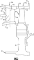
- FIG. 2 a cross-sectional view through a high pressure turbine section 54 is illustrated.
- a first stage array 54a of circumferentially spaced fixed vanes 60 is included.
- the turbine blades each include a tip 80 adjacent to a blade outer air seal 70 of a case structure 72.
- the first stage array 54b of turbine blades are arranged within a core flow path C and are operatively connected to a spool 32.
- Each vane 60 includes an inner platform 74 and an outer platform 76 respectively defining inner and outer flow paths.
- the platforms 74, 76 are interconnected by an airfoil section 78 extending in a radial direction Z. It should be understood that the turbine vanes may be discrete from one another or arranged in integrated clusters.
- the airfoil section 78 includes leading and trailing edges 82, 84.
- the airfoil section 78 is provided between pressure (concave) and suction (convex) sides 85, 87 in an airfoil thickness direction, which is generally perpendicular to a chord-wise direction provided between the leading and trailing edges 82, 84 ( Figure 3 ).
- Multiple turbine vanes 60 are arranged circumferentially in a circumferential direction R.
- the airfoil section 78 typically includes multiple cooling holes (not shown).
- the first stage array 54a consists of 32 turbine vanes 60, but the number may vary according to engine size.
- the turbine vanes 60 in one example are formed of a ceramic matrix composite (CMC) material.
- CMC ceramic matrix composite
- a CMC material is one that includes fibers (such as carbon, silicon or glass fibers, as example) supported within a ceramic matrix.
- FIG 3 illustrates an example stator vane 60.
- the stator vane 60 is a singlet, meaning the stator vane 60 includes only one airfoil section 78.
- This disclosure is not limited to singlets, it may be doublets, triplets etc., however.
- the example stator vane 60 is shown in Figure 2 in the high pressure turbine section 54, one would understand that this disclosure can be used in other sections of the engine 20 such as the mid-turbine frame 57.
- the airfoil section 78 is connected to both an inner platform 74 and an outer platform 76.
- the inner and outer platforms 74, 76 each respectively include a fore end 74F, 76F, an aft end 74A, 76A, and circumferential ends 74C, 76C (relative to the circumferential direction R in Figure 4 ).
- the terms "fore,” “aft,” and “circumferential” are made with the normal operational attitude of the stator vane 60.
- flanges 90 are provided on opposite circumferential ends 74C, 76C of both the inner platform 74 and the outer platform 76.
- Each of the flanges 90 is provided with an inner face 90I, an outer face 90F, and a plurality of openings 92 therein.
- the inner and outer faces 90I, 90F extend radially in the Z direction and are generally perpendicular to the respective inner and outer platform 74, 76.
- each of the openings 92 are configured to receive fasteners 94 (illustrated schematically in Figures 5A-5B ) to fasten adjacent stator vanes 60 together, and to fasten the stator vanes 60 to a support structure, such as the engine static structure 36 ( Figure 4 ).
- flanges 90 are provided such that their length dimension L runs in a direction generally parallel to the engine central longitudinal axis X, and generally perpendicular to the radial direction Z along the circumferential ends 74C, 76C of the platforms 74, 76.
- stator vane 60 is made of a CMC material, and the flanges 90 are formed integrally with the stator vane 60 during a molding process. Because the stator vanes 60 are formed of a CMC material, they are suitable for use in the high pressure turbine section 54, however this disclosure is not limited to a particular section of the gas turbine engine 20.
- FIG. 4 illustrates an example arrangement of a stationary stage of the gas turbine engine 20, here the first stage array 54a.
- stator vanes 60 are fastened together with adjacent, similar stator vanes 60 (e.g., the stator vanes 60 each include platforms 74, 76 configured for circumferential attachment, as illustrated) such that outer faces 90F of the flanges 90 directly abut one another in a circumferential direction R, relative to the engine central longitudinal axis X, such that the outer faces 90F directly abut one another.
- This arrangement provides the first stage array 54a with a relatively high hoop stiffness in the circumferential direction R, which reduces deflection of the inner and outer platforms 74, 76 and maintains the overall stability of the first stage array 54a.
- the adjacent stator vanes 60 can further be configured to carry a seal therebetween, for example, at a point between adjacent stator vanes 60 (illustrated at 100) to prevent leakage between the adjacent stator vanes 60.
- Figures 5A-5B schematically illustrate examples for fastening adjacent stator vanes 60 together.
- Figures 5A-5B illustrate examples where fasteners 94, which could be nuts and bolts, are used to fasten the adjacent stator vanes 60 together.
- the fasteners 94 can include beveled, or spring, washers to maintain a preload while accommodating differences in thermal growth.
- the fasteners 94 further tie the stator vanes 60 to couplings 95A-95B such that the adjacent stator vanes are tied together.
- the couplings 95A-95B essentially can act as washers and further ensure a close connection between adjacent stator vanes 60.
- the outer coupling 95A is connected to an engine static structure 36 in one example.
- the fasteners 94 are positioned within the openings 92 of adjacent flanges 90 such that the fasteners 94 are outside the gas flowpath. Thus, exposure of the fasteners 94 to exhaust gases is reduced.
- resilient members 99 are positioned against the outer platform 76 ( Figure 5A ) and optionally against the inner platform ( Figure 5B ) as well.
- the resilient members 99 further ensure an adequate connection between the adjacent stator vanes 60 by providing additional support to the flanges 90, which aids in taking the load off of the fasteners 94 and further reduces bending of the flanges 90, in particular in the right and left relative to Figure 5A .
- the flanges 90 adjacent the outer platform 76 are fastened together while the flanges 90 adjacent the inner platform 74 are not fastened together. This allows the inner platforms 74 to move freely in a radial direction, and thus can prevent fighting between the adjacent stator vanes 60, and reduces stresses experienced thereby.
Description
- Gas turbine engines typically include a compressor section, a combustor section and a turbine section. During operation, air is pressurized in the compressor section and is mixed with fuel and burned in the combustor section to generate hot combustion gases. The hot combustion gases are communicated through the turbine section, which extracts energy from the hot combustion gases to power the compressor section and other gas turbine engine loads.
- Both the compressor and turbine sections may include alternating series of rotating blades and stationary vanes that extend into the core flow path of the gas turbine engine. For example, in the turbine section, turbine blades rotate and extract energy from the hot combustion gases that are communicated along the core flow path of the gas turbine engine. The turbine vanes, which generally do not rotate, guide the airflow and prepare it for the next set of blades.
- In turbine vane design, there is an emphasis on stress-resistant airfoil and platform designs, with reduced losses, increased lift and turning efficiency, and improved turbine performance and service life.
-
US 2005/254944 A1 ,EP 0903467 A2 andUS 4492517 A each disclose a gas turbine engine, comprising a plurality of stator vanes, each of the plurality of stator vanes including an airfoil section and a platform provided at an end of the airfoil section, the platform provided with flanges on opposed ends thereof, the flanges being fastened to corresponding flanges of an adjacent one of the plurality of stator vanes. -
EP 1126135 discloses a gas turbine engine according to the preamble of claim 1. - In one aspect of the disclosure, a gas turbine engine includes a plurality of stator vanes. Each of the plurality of stator vanes includes an airfoil section and a platform provided at an end of the airfoil section. The platform is provided with flanges on opposed ends thereof, and the flanges are fastened to corresponding flanges of an adjacent one of the plurality of stator vanes. At least one of the plurality of stator vanes is made of a ceramic matrix composite (CMC) material. The flanges are integrally formed with the stator vane. The gas turbine engine is characterised in that the flanges of each platform are provided on circumferential ends of the platform.
- In a further embodiment of any of the above, a length dimension of the flanges is provided in a direction generally parallel to an engine central longitudinal axis.
- In a further embodiment of any of the above, the flanges include inner and outer faces generally perpendicular the platform.
- In a further embodiment of any of the above, the flanges are fastened to one another such that the outer faces of the flanges directly abut one another.
- In a further embodiment of any of the above, the flanges include openings configured to receive fasteners.
- In a further embodiment of any of the above, the fasteners include at least one of bolts, pins, and springs.
- In a further embodiment of any of the above, the fasteners fasten adjacent flanges to one another.
- In a further embodiment of any of the above, the fasteners fasten the flanges to a static structure of the gas turbine engine via a respective coupling.
- In a further embodiment of any of the above, the gas turbine engine includes at least one resilient member connected to the flange and to the platform to reduce bending of the flange.
- In a further embodiment of any of the above, each of the plurality of stator vanes includes a first platform at a radially outer end of the airfoil section, and a second platform at a radially inner end of the airfoil section, each of the first and second platforms provided with flanges on opposed ends thereof, wherein the flanges associated with the first platform are fastened to flanges of a first platform of an adjacent stator vane, and the flanges associated with the second platform are not fastened to the flanges of an adjacent stator vane to allow the second platform to be radially free.
- In a further embodiment of any of the above, the gas turbine engine includes a compressor section, a combustor section, and a turbine section, the turbine section including a stationary stage, the stator vanes provided in the stationary stage.
- These and other features of the present disclosure can be best understood from the following drawings and detailed description.
- The drawings can be briefly described as follows:
-
Figure 1 schematically illustrates a gas turbine engine embodiment. -
Figure 2 is a cross-sectional view through a high pressure turbine section. -
Figure 3 is a perspective view of an example stator vane. -
Figure 4 is an example stage of the gas turbine engine, showing a plurality of stator vanes. -
Figures 5A-5B schematically illustrate examples for fastening adjacent stator vanes to one another. -
Figure 1 schematically illustrates an examplegas turbine engine 20 that includes afan section 22, acompressor section 24, acombustor section 26 and aturbine section 28. Alternative engines might include an augmenter section (not shown) among other systems or features. Thefan section 22 drives air along a bypass flow path B while thecompressor section 24 draws air in along a core flow path C where air is compressed and communicated to acombustor section 26. In thecombustor section 26, air is mixed with fuel and ignited to generate a high pressure exhaust gas stream that expands through theturbine section 28 where energy is extracted and utilized to drive thefan section 22 and thecompressor section 24. - Although the disclosed non-limiting embodiment depicts a turbofan gas turbine engine, it should be understood that the concepts described herein are not limited to use with turbofans as the teachings may be applied to other types of turbine engines; for example a turbine engine including a three-spool architecture in which three spools concentrically rotate about a common axis and where a low spool enables a low pressure turbine to drive a fan via a gearbox, an intermediate spool that enables an intermediate pressure turbine to drive a first compressor of the compressor section, and a high spool that enables a high pressure turbine to drive a high pressure compressor of the compressor section. The concepts disclosed herein can further be applied outside of gas turbine engines, such as in the context of wind turbines.
- The
example engine 20 generally includes alow speed spool 30 and ahigh speed spool 32 mounted for rotation about an engine central longitudinal axis X relative to an enginestatic structure 36 viaseveral bearing systems 38. It should be understood thatvarious bearing systems 38 at various locations may alternatively or additionally be provided. - The
low speed spool 30 generally includes aninner shaft 40 that connects afan 42 and a low pressure (or first) compressor section 44 to a low pressure (or first)turbine section 46. Theinner shaft 40 drives thefan 42 through a speed change device, such as a gearedarchitecture 48, to drive thefan 42 at a lower speed than thelow speed spool 30. The high-speed spool 32 includes anouter shaft 50 that interconnects a high pressure (or second)compressor section 52 and a high pressure (or second)turbine section 54. Theinner shaft 40 and theouter shaft 50 are concentric and rotate via thebearing systems 38 about the engine central longitudinal axis X. - A
combustor 56 is arranged between thehigh pressure compressor 52 and thehigh pressure turbine 54. In one example, thehigh pressure turbine 54 includes at least two stages to provide a double stagehigh pressure turbine 54. In another example, thehigh pressure turbine 54 includes only a single stage. As used herein, a "high pressure" compressor or turbine experiences a higher pressure than a corresponding "low pressure" compressor or turbine. - The example
low pressure turbine 46 has a pressure ratio that is greater than about five (5). The pressure ratio of the examplelow pressure turbine 46 is measured prior to an inlet of thelow pressure turbine 46 as related to the pressure measured at the outlet of thelow pressure turbine 46 prior to an exhaust nozzle. - A
mid-turbine frame 57 of the enginestatic structure 36 is arranged generally between thehigh pressure turbine 54 and thelow pressure turbine 46. Themid-turbine frame 57 further supports bearingsystems 38 in theturbine section 28 as well as setting airflow entering thelow pressure turbine 46. - The core airflow C is compressed by the low pressure compressor 44 then by the
high pressure compressor 52 mixed with fuel and ignited in thecombustor 56 to produce high speed exhaust gases that are then expanded through thehigh pressure turbine 54 andlow pressure turbine 46. Themid-turbine frame 57 includesvanes 59, which are in the core airflow path and function as an inlet guide vane for thelow pressure turbine 46. Utilizing thevane 59 of themid-turbine frame 57 as the inlet guide vane forlow pressure turbine 46 decreases the length of thelow pressure turbine 46 without increasing the axial length of themid-turbine frame 57. Reducing or eliminating the number of vanes in thelow pressure turbine 46 shortens the axial length of theturbine section 28. Thus, the compactness of thegas turbine engine 20 is increased and a higher power density may be achieved. - The disclosed
gas turbine engine 20 in one example is a high-bypass geared aircraft engine. In a further example, thegas turbine engine 20 includes a bypass ratio greater than about six (6), with an example embodiment being greater than about ten (10). The example gearedarchitecture 48 is an epicyclical gear train, such as a planetary gear system, star gear system or other known gear system, with a gear reduction ratio of greater than about 2.3. - In one disclosed embodiment, the
gas turbine engine 20 includes a bypass ratio greater than about ten (10:1) and the fan diameter is significantly larger than an outer diameter of the low pressure compressor 44. It should be understood, however, that the above parameters are only exemplary of one embodiment of a gas turbine engine including a geared architecture and that the present disclosure is applicable to other gas turbine engines. - A significant amount of thrust is provided by the bypass flow B due to the high bypass ratio. The
fan section 22 of theengine 20 is designed for a particular flight condition -- typically cruise at about 0.8 Mach and about 35,000 feet. The flight condition of 0.8 Mach and 35,000 ft., with the engine at its best fuel consumption - also known as "bucket cruise Thrust Specific Fuel Consumption ('TSFC')" - is the industry standard parameter of pound-mass (lbm) of fuel per hour being burned divided by pound-force (lbf) of thrust the engine produces at that minimum point. - "Low fan pressure ratio" is the pressure ratio across the fan blade alone, without a Fan Exit Guide Vane ("FEGV") system. The low fan pressure ratio as disclosed herein according to one non-limiting embodiment is less than about 1.50. In another non-limiting embodiment the low fan pressure ratio is less than about 1.45.
- "Low corrected fan tip speed" is the actual fan tip speed in ft/sec divided by an industry standard temperature correction of [(Tram °R) / (518.7 °R)]0.5. The "Low corrected fan tip speed", as disclosed herein according to one non-limiting embodiment, is less than about 1150 ft/second.
- The example gas turbine engine includes the
fan 42 that comprises in one non-limiting embodiment less than about twenty-six (26) fan blades. In another non-limiting embodiment, thefan section 22 includes less than about twenty (20) fan blades. Moreover, in one disclosed embodiment thelow pressure turbine 46 includes no more than about six (6) turbine rotors schematically indicated at 34. In another non-limiting example embodiment thelow pressure turbine 46 includes about three (3) turbine rotors. A ratio between the number offan blades 42 and the number of low pressure turbine rotors is between about 3.3 and about 8.6. The examplelow pressure turbine 46 provides the driving power to rotate thefan section 22 and therefore the relationship between the number of turbine rotors 34 in thelow pressure turbine 46 and the number ofblades 42 in thefan section 22 disclose an examplegas turbine engine 20 with increased power transfer efficiency. - Referring to
Figure 2 , a cross-sectional view through a highpressure turbine section 54 is illustrated. In the example highpressure turbine section 54, afirst stage array 54a of circumferentially spaced fixedvanes 60 is included. Afirst stage array 54b of circumferentially spacedturbine blades 64, mounted to arotor disk 68, is arranged axially downstream of the first fixedvane array 54a. - The turbine blades each include a
tip 80 adjacent to a bladeouter air seal 70 of acase structure 72. Thefirst stage array 54b of turbine blades are arranged within a core flow path C and are operatively connected to aspool 32. - Each
vane 60 includes aninner platform 74 and anouter platform 76 respectively defining inner and outer flow paths. Theplatforms airfoil section 78 extending in a radial direction Z. It should be understood that the turbine vanes may be discrete from one another or arranged in integrated clusters. Theairfoil section 78 includes leading and trailingedges - The
airfoil section 78 is provided between pressure (concave) and suction (convex) sides 85, 87 in an airfoil thickness direction, which is generally perpendicular to a chord-wise direction provided between the leading and trailingedges 82, 84 (Figure 3 ).Multiple turbine vanes 60 are arranged circumferentially in a circumferential direction R. Theairfoil section 78 typically includes multiple cooling holes (not shown). - In one example, the
first stage array 54a consists of 32turbine vanes 60, but the number may vary according to engine size. The turbine vanes 60 in one example are formed of a ceramic matrix composite (CMC) material. As is known in this art, a CMC material is one that includes fibers (such as carbon, silicon or glass fibers, as example) supported within a ceramic matrix. -
Figure 3 illustrates anexample stator vane 60. In this example, thestator vane 60 is a singlet, meaning thestator vane 60 includes only oneairfoil section 78. This disclosure is not limited to singlets, it may be doublets, triplets etc., however. Further, while theexample stator vane 60 is shown inFigure 2 in the highpressure turbine section 54, one would understand that this disclosure can be used in other sections of theengine 20 such as themid-turbine frame 57. - In this example, the
airfoil section 78 is connected to both aninner platform 74 and anouter platform 76. The inner andouter platforms fore end aft end Figure 4 ). As one would appreciate, the terms "fore," "aft," and "circumferential" are made with the normal operational attitude of thestator vane 60. In this example,flanges 90 are provided on opposite circumferential ends 74C, 76C of both theinner platform 74 and theouter platform 76. - Each of the
flanges 90 is provided with an inner face 90I, anouter face 90F, and a plurality ofopenings 92 therein. The inner andouter faces 90I, 90F extend radially in the Z direction and are generally perpendicular to the respective inner andouter platform openings 92 are configured to receive fasteners 94 (illustrated schematically inFigures 5A-5B ) to fastenadjacent stator vanes 60 together, and to fasten thestator vanes 60 to a support structure, such as the engine static structure 36 (Figure 4 ). - With continued reference to
Figure 3 ,flanges 90 are provided such that their length dimension L runs in a direction generally parallel to the engine central longitudinal axis X, and generally perpendicular to the radial direction Z along the circumferential ends 74C, 76C of theplatforms - In one example, the
stator vane 60 is made of a CMC material, and theflanges 90 are formed integrally with thestator vane 60 during a molding process. Because thestator vanes 60 are formed of a CMC material, they are suitable for use in the highpressure turbine section 54, however this disclosure is not limited to a particular section of thegas turbine engine 20. -
Figure 4 illustrates an example arrangement of a stationary stage of thegas turbine engine 20, here thefirst stage array 54a. In the example,stator vanes 60 are fastened together with adjacent, similar stator vanes 60 (e.g., thestator vanes 60 each includeplatforms outer faces 90F of theflanges 90 directly abut one another in a circumferential direction R, relative to the engine central longitudinal axis X, such that the outer faces 90F directly abut one another. This arrangement provides thefirst stage array 54a with a relatively high hoop stiffness in the circumferential direction R, which reduces deflection of the inner andouter platforms first stage array 54a. - The
adjacent stator vanes 60 can further be configured to carry a seal therebetween, for example, at a point between adjacent stator vanes 60 (illustrated at 100) to prevent leakage between theadjacent stator vanes 60. -
Figures 5A-5B schematically illustrate examples for fasteningadjacent stator vanes 60 together. In particular,Figures 5A-5B illustrate examples wherefasteners 94, which could be nuts and bolts, are used to fasten theadjacent stator vanes 60 together. In situations where the vanes and bolts are different materials, thefasteners 94 can include beveled, or spring, washers to maintain a preload while accommodating differences in thermal growth. Thefasteners 94 further tie thestator vanes 60 tocouplings 95A-95B such that the adjacent stator vanes are tied together. Thecouplings 95A-95B essentially can act as washers and further ensure a close connection betweenadjacent stator vanes 60. Theouter coupling 95A is connected to an enginestatic structure 36 in one example. - With further reference to
Figures 5A-5B , and also with reference toFigure 3 , thefasteners 94 are positioned within theopenings 92 ofadjacent flanges 90 such that thefasteners 94 are outside the gas flowpath. Thus, exposure of thefasteners 94 to exhaust gases is reduced. - With continued reference to
Figures 5A-5B ,resilient members 99 are positioned against the outer platform 76 (Figure 5A ) and optionally against the inner platform (Figure 5B ) as well. Theresilient members 99 further ensure an adequate connection between theadjacent stator vanes 60 by providing additional support to theflanges 90, which aids in taking the load off of thefasteners 94 and further reduces bending of theflanges 90, in particular in the right and left relative toFigure 5A . - In an alternate configuration from those shown in
Figures 5A and 5B , theflanges 90 adjacent theouter platform 76 are fastened together while theflanges 90 adjacent theinner platform 74 are not fastened together. This allows theinner platforms 74 to move freely in a radial direction, and thus can prevent fighting between theadjacent stator vanes 60, and reduces stresses experienced thereby. - Although the different examples have the specific components shown in the illustrations, embodiments of this disclosure are not limited to those particular combinations. It is possible to use some of the components or features from one of the examples in combination with features or components from another one of the examples.
- One of ordinary skill in this art would understand that the above-described embodiments are exemplary and non-limiting. That is, modifications of this disclosure would come within the scope of the claims. Accordingly, the following claims should be studied to determine their true scope and content.
Claims (11)
- A gas turbine engine (20), comprising a plurality of stator vanes (60), each of the plurality of stator vanes including an airfoil section (78) and a platform (74, 76) provided at an end of the airfoil section, the platform provided with flanges (90) on opposed ends thereof, the flanges being fastened to corresponding flanges of an adjacent one of the plurality of stator vanes;
wherein at least one of the plurality of stator vanes is made of a ceramic matrix composite (CMC) material;
wherein for each of the plurality of stator vanes, the flanges are integrally formed with the stator vane; and
wherein the gas turbine engine is characterised in that the flanges of each platform are provided on circumferential ends of the platform. - The gas turbine engine as recited in claim 1, wherein a length dimension of the flanges is provided in a direction generally parallel to an engine central longitudinal axis.
- The gas turbine engine as recited in claim 1 or 2, wherein the flanges include inner (90I) and outer (90F) faces generally perpendicular to the platform.
- The gas turbine engine as recited in any preceding claim, wherein the flanges are fastened to one another such that the outer faces of the flanges directly abut one another.
- The gas turbine engine as recited in any preceding claim, wherein the flanges include openings (92) configured to receive fasteners (94).
- The gas turbine engine as recited in claim 5, wherein the fasteners include at least one of bolts, pins, and springs.
- The gas turbine engine as recited in claim 5 or 6, wherein the fasteners fasten adjacent flanges to one another.
- The gas turbine engine as recited in claim 5, 6 or 7, wherein the fasteners fasten the flanges to a static structure of the gas turbine engine via a respective coupling (95A-95B).
- The gas turbine engine as recited in any preceding claim, including at least one resilient member (99) connected to the flange and to the platform to reduce bending of the flange.
- The gas turbine engine as recited in any preceding claim, further including a compressor section (24), a combustor section (26), and a turbine section (28), the turbine section including a stationary stage, wherein the stator vanes are provided in the stationary stage.
- The gas turbine engine as recited in any preceding claim, wherein each of the plurality of stator vanes includes a first platform (76) at a radially outer end of the airfoil section, and a second platform (74) at a radially inner end of the airfoil section, each of the first and second platforms are provided with flanges on opposed ends thereof, the flanges associated with the first platform are fastened to flanges of a first platform of an adjacent stator vane, and the flanges associated with the second platform are not fastened to the flanges of an adjacent stator vane to allow the second platform to be radially free.
Applications Claiming Priority (2)
| Application Number | Priority Date | Filing Date | Title |
|---|---|---|---|
| US201361811149P | 2013-04-12 | 2013-04-12 | |
| PCT/US2014/033719 WO2015023324A2 (en) | 2013-04-12 | 2014-04-11 | Stator vane platform with flanges |
Publications (3)
| Publication Number | Publication Date |
|---|---|
| EP2984292A2 EP2984292A2 (en) | 2016-02-17 |
| EP2984292A4 EP2984292A4 (en) | 2016-08-10 |
| EP2984292B1 true EP2984292B1 (en) | 2018-06-06 |
Family
ID=52468770
Family Applications (1)
| Application Number | Title | Priority Date | Filing Date |
|---|---|---|---|
| EP14836531.5A Active EP2984292B1 (en) | 2013-04-12 | 2014-04-11 | Stator vane platform with flanges |
Country Status (3)
| Country | Link |
|---|---|
| US (1) | US20160069199A1 (en) |
| EP (1) | EP2984292B1 (en) |
| WO (1) | WO2015023324A2 (en) |
Families Citing this family (8)
| Publication number | Priority date | Publication date | Assignee | Title |
|---|---|---|---|---|
| US10202857B2 (en) * | 2015-02-06 | 2019-02-12 | United Technologies Corporation | Vane stages |
| CA2925588A1 (en) | 2015-04-29 | 2016-10-29 | Rolls-Royce Corporation | Brazed blade track for a gas turbine engine |
| US10550709B2 (en) * | 2015-04-30 | 2020-02-04 | Rolls-Royce North American Technologies Inc. | Full hoop blade track with flanged segments |
| US10443625B2 (en) | 2016-09-21 | 2019-10-15 | General Electric Company | Airfoil singlets |
| US11466577B2 (en) * | 2019-10-04 | 2022-10-11 | Raytheon Technologies Corporation | CMC vane mate face flange |
| US11073039B1 (en) | 2020-01-24 | 2021-07-27 | Rolls-Royce Plc | Ceramic matrix composite heat shield for use in a turbine vane and a turbine shroud ring |
| US11454129B1 (en) | 2021-04-02 | 2022-09-27 | Raytheon Technologies Corporation | CMC component flow discourager flanges |
| US11655758B1 (en) * | 2022-03-31 | 2023-05-23 | Raytheon Technologies Corporation | CMC vane mate face flanges with through-ply seal slots |
Family Cites Families (15)
| Publication number | Priority date | Publication date | Assignee | Title |
|---|---|---|---|---|
| US3966353A (en) * | 1975-02-21 | 1976-06-29 | Westinghouse Electric Corporation | Ceramic-to-metal (or ceramic) cushion/seal for use with three piece ceramic stationary vane assembly |
| US4015910A (en) * | 1976-03-09 | 1977-04-05 | The United States Of America As Represented By The Secretary Of The Air Force | Bolted paired vanes for turbine |
| US4492517A (en) * | 1983-01-06 | 1985-01-08 | General Electric Company | Segmented inlet nozzle for gas turbine, and methods of installation |
| GB2267541B (en) * | 1992-06-04 | 1995-08-09 | Rolls Royce Plc | Mounting gas turbine outlet guide vanes |
| CA2231986A1 (en) * | 1997-01-10 | 1999-09-12 | Masahito Kataoka | Stationary blade of integrated segment construction and manufacturing method therefor |
| US5848874A (en) * | 1997-05-13 | 1998-12-15 | United Technologies Corporation | Gas turbine stator vane assembly |
| JPH11125102A (en) * | 1997-10-22 | 1999-05-11 | Mitsubishi Heavy Ind Ltd | Gas turbine stator blade |
| EP0903467B1 (en) * | 1997-09-17 | 2004-07-07 | Mitsubishi Heavy Industries, Ltd. | Paired stator vanes |
| JP4060981B2 (en) * | 1998-04-08 | 2008-03-12 | 本田技研工業株式会社 | Gas turbine stationary blade structure and unit thereof |
| US6200092B1 (en) * | 1999-09-24 | 2001-03-13 | General Electric Company | Ceramic turbine nozzle |
| DE10051223A1 (en) * | 2000-10-16 | 2002-04-25 | Alstom Switzerland Ltd | Connectable stator elements |
| US9068464B2 (en) * | 2002-09-17 | 2015-06-30 | Siemens Energy, Inc. | Method of joining ceramic parts and articles so formed |
| US7101150B2 (en) | 2004-05-11 | 2006-09-05 | Power Systems Mfg, Llc | Fastened vane assembly |
| US7329087B2 (en) * | 2005-09-19 | 2008-02-12 | General Electric Company | Seal-less CMC vane to platform interfaces |
| US8834109B2 (en) * | 2011-08-03 | 2014-09-16 | United Technologies Corporation | Vane assembly for a gas turbine engine |
-
2014
- 2014-04-11 EP EP14836531.5A patent/EP2984292B1/en active Active
- 2014-04-11 WO PCT/US2014/033719 patent/WO2015023324A2/en active Application Filing
- 2014-04-11 US US14/783,965 patent/US20160069199A1/en not_active Abandoned
Non-Patent Citations (1)
| Title |
|---|
| None * |
Also Published As
| Publication number | Publication date |
|---|---|
| WO2015023324A2 (en) | 2015-02-19 |
| US20160069199A1 (en) | 2016-03-10 |
| WO2015023324A3 (en) | 2015-04-09 |
| EP2984292A4 (en) | 2016-08-10 |
| EP2984292A2 (en) | 2016-02-17 |
Similar Documents
| Publication | Publication Date | Title |
|---|---|---|
| EP2984292B1 (en) | Stator vane platform with flanges | |
| EP2935799B1 (en) | Manufacture of full ring strut vane pack | |
| EP3030754B1 (en) | Boas with radial load feature | |
| EP3594452B1 (en) | Seal segment for a gas turbine engine | |
| EP2971585B1 (en) | Gas turbine engine turbine vane rail seal | |
| US10458265B2 (en) | Integrally bladed rotor | |
| EP3026217B1 (en) | Turbine rotor or stator segmented sideplates with anti-rotation | |
| US11156109B2 (en) | Blade retention features for turbomachines | |
| EP3246517B1 (en) | Fastener openings for stress distribution | |
| EP2935791A1 (en) | Lightweight shrouded fan | |
| EP2943658B2 (en) | Stator anti-rotation device | |
| EP3192968B1 (en) | Mini-disk for gas turbine engine | |
| CN112392549A (en) | Blade retention feature for a turbomachine | |
| EP3011155B1 (en) | Heat shield | |
| EP2909463B1 (en) | Turbofan engine and corresponding method of assembling a front portion of a turbofan engine. | |
| EP3453836B1 (en) | Stator vane support with anti-rotation features | |
| US10711648B2 (en) | Nosecone support |
Legal Events
| Date | Code | Title | Description |
|---|---|---|---|
| PUAI | Public reference made under article 153(3) epc to a published international application that has entered the european phase |
Free format text: ORIGINAL CODE: 0009012 |
|
| 17P | Request for examination filed |
Effective date: 20151106 |
|
| AK | Designated contracting states |
Kind code of ref document: A2 Designated state(s): AL AT BE BG CH CY CZ DE DK EE ES FI FR GB GR HR HU IE IS IT LI LT LU LV MC MK MT NL NO PL PT RO RS SE SI SK SM TR |
|
| AX | Request for extension of the european patent |
Extension state: BA ME |
|
| DAX | Request for extension of the european patent (deleted) | ||
| A4 | Supplementary search report drawn up and despatched |
Effective date: 20160707 |
|
| RIC1 | Information provided on ipc code assigned before grant |
Ipc: F01D 5/22 20060101ALI20160701BHEP Ipc: F02C 7/20 20060101ALI20160701BHEP Ipc: F01D 9/02 20060101AFI20160701BHEP Ipc: F01D 25/28 20060101ALI20160701BHEP |
|
| RAP1 | Party data changed (applicant data changed or rights of an application transferred) |
Owner name: UNITED TECHNOLOGIES CORPORATION |
|
| RIC1 | Information provided on ipc code assigned before grant |
Ipc: F01D 9/04 20060101ALI20170228BHEP Ipc: F01D 5/22 20060101ALI20170228BHEP Ipc: F01D 25/24 20060101ALI20170228BHEP Ipc: F01D 25/28 20060101ALI20170228BHEP Ipc: F02C 7/20 20060101ALI20170228BHEP Ipc: F01D 9/02 20060101AFI20170228BHEP |
|
| STAA | Information on the status of an ep patent application or granted ep patent |
Free format text: STATUS: EXAMINATION IS IN PROGRESS |
|
| 17Q | First examination report despatched |
Effective date: 20170529 |
|
| GRAP | Despatch of communication of intention to grant a patent |
Free format text: ORIGINAL CODE: EPIDOSNIGR1 |
|
| STAA | Information on the status of an ep patent application or granted ep patent |
Free format text: STATUS: GRANT OF PATENT IS INTENDED |
|
| INTG | Intention to grant announced |
Effective date: 20171205 |
|
| GRAS | Grant fee paid |
Free format text: ORIGINAL CODE: EPIDOSNIGR3 |
|
| GRAA | (expected) grant |
Free format text: ORIGINAL CODE: 0009210 |
|
| STAA | Information on the status of an ep patent application or granted ep patent |
Free format text: STATUS: THE PATENT HAS BEEN GRANTED |
|
| AK | Designated contracting states |
Kind code of ref document: B1 Designated state(s): AL AT BE BG CH CY CZ DE DK EE ES FI FR GB GR HR HU IE IS IT LI LT LU LV MC MK MT NL NO PL PT RO RS SE SI SK SM TR |
|
| REG | Reference to a national code |
Ref country code: GB Ref legal event code: FG4D |
|
| REG | Reference to a national code |
Ref country code: CH Ref legal event code: EP Ref country code: AT Ref legal event code: REF Ref document number: 1006311 Country of ref document: AT Kind code of ref document: T Effective date: 20180615 |
|
| REG | Reference to a national code |
Ref country code: IE Ref legal event code: FG4D |
|
| REG | Reference to a national code |
Ref country code: DE Ref legal event code: R096 Ref document number: 602014026792 Country of ref document: DE |
|
| REG | Reference to a national code |
Ref country code: NL Ref legal event code: MP Effective date: 20180606 |
|
| REG | Reference to a national code |
Ref country code: LT Ref legal event code: MG4D |
|
| PG25 | Lapsed in a contracting state [announced via postgrant information from national office to epo] |
Ref country code: LT Free format text: LAPSE BECAUSE OF FAILURE TO SUBMIT A TRANSLATION OF THE DESCRIPTION OR TO PAY THE FEE WITHIN THE PRESCRIBED TIME-LIMIT Effective date: 20180606 Ref country code: CY Free format text: LAPSE BECAUSE OF FAILURE TO SUBMIT A TRANSLATION OF THE DESCRIPTION OR TO PAY THE FEE WITHIN THE PRESCRIBED TIME-LIMIT Effective date: 20180606 Ref country code: NO Free format text: LAPSE BECAUSE OF FAILURE TO SUBMIT A TRANSLATION OF THE DESCRIPTION OR TO PAY THE FEE WITHIN THE PRESCRIBED TIME-LIMIT Effective date: 20180906 Ref country code: BG Free format text: LAPSE BECAUSE OF FAILURE TO SUBMIT A TRANSLATION OF THE DESCRIPTION OR TO PAY THE FEE WITHIN THE PRESCRIBED TIME-LIMIT Effective date: 20180906 Ref country code: ES Free format text: LAPSE BECAUSE OF FAILURE TO SUBMIT A TRANSLATION OF THE DESCRIPTION OR TO PAY THE FEE WITHIN THE PRESCRIBED TIME-LIMIT Effective date: 20180606 Ref country code: SE Free format text: LAPSE BECAUSE OF FAILURE TO SUBMIT A TRANSLATION OF THE DESCRIPTION OR TO PAY THE FEE WITHIN THE PRESCRIBED TIME-LIMIT Effective date: 20180606 Ref country code: FI Free format text: LAPSE BECAUSE OF FAILURE TO SUBMIT A TRANSLATION OF THE DESCRIPTION OR TO PAY THE FEE WITHIN THE PRESCRIBED TIME-LIMIT Effective date: 20180606 |
|
| PG25 | Lapsed in a contracting state [announced via postgrant information from national office to epo] |
Ref country code: RS Free format text: LAPSE BECAUSE OF FAILURE TO SUBMIT A TRANSLATION OF THE DESCRIPTION OR TO PAY THE FEE WITHIN THE PRESCRIBED TIME-LIMIT Effective date: 20180606 Ref country code: LV Free format text: LAPSE BECAUSE OF FAILURE TO SUBMIT A TRANSLATION OF THE DESCRIPTION OR TO PAY THE FEE WITHIN THE PRESCRIBED TIME-LIMIT Effective date: 20180606 Ref country code: GR Free format text: LAPSE BECAUSE OF FAILURE TO SUBMIT A TRANSLATION OF THE DESCRIPTION OR TO PAY THE FEE WITHIN THE PRESCRIBED TIME-LIMIT Effective date: 20180907 Ref country code: HR Free format text: LAPSE BECAUSE OF FAILURE TO SUBMIT A TRANSLATION OF THE DESCRIPTION OR TO PAY THE FEE WITHIN THE PRESCRIBED TIME-LIMIT Effective date: 20180606 |
|
| REG | Reference to a national code |
Ref country code: AT Ref legal event code: MK05 Ref document number: 1006311 Country of ref document: AT Kind code of ref document: T Effective date: 20180606 |
|
| PG25 | Lapsed in a contracting state [announced via postgrant information from national office to epo] |
Ref country code: NL Free format text: LAPSE BECAUSE OF FAILURE TO SUBMIT A TRANSLATION OF THE DESCRIPTION OR TO PAY THE FEE WITHIN THE PRESCRIBED TIME-LIMIT Effective date: 20180606 |
|
| PG25 | Lapsed in a contracting state [announced via postgrant information from national office to epo] |
Ref country code: AT Free format text: LAPSE BECAUSE OF FAILURE TO SUBMIT A TRANSLATION OF THE DESCRIPTION OR TO PAY THE FEE WITHIN THE PRESCRIBED TIME-LIMIT Effective date: 20180606 Ref country code: PL Free format text: LAPSE BECAUSE OF FAILURE TO SUBMIT A TRANSLATION OF THE DESCRIPTION OR TO PAY THE FEE WITHIN THE PRESCRIBED TIME-LIMIT Effective date: 20180606 Ref country code: CZ Free format text: LAPSE BECAUSE OF FAILURE TO SUBMIT A TRANSLATION OF THE DESCRIPTION OR TO PAY THE FEE WITHIN THE PRESCRIBED TIME-LIMIT Effective date: 20180606 Ref country code: SK Free format text: LAPSE BECAUSE OF FAILURE TO SUBMIT A TRANSLATION OF THE DESCRIPTION OR TO PAY THE FEE WITHIN THE PRESCRIBED TIME-LIMIT Effective date: 20180606 Ref country code: RO Free format text: LAPSE BECAUSE OF FAILURE TO SUBMIT A TRANSLATION OF THE DESCRIPTION OR TO PAY THE FEE WITHIN THE PRESCRIBED TIME-LIMIT Effective date: 20180606 Ref country code: EE Free format text: LAPSE BECAUSE OF FAILURE TO SUBMIT A TRANSLATION OF THE DESCRIPTION OR TO PAY THE FEE WITHIN THE PRESCRIBED TIME-LIMIT Effective date: 20180606 Ref country code: IS Free format text: LAPSE BECAUSE OF FAILURE TO SUBMIT A TRANSLATION OF THE DESCRIPTION OR TO PAY THE FEE WITHIN THE PRESCRIBED TIME-LIMIT Effective date: 20181006 |
|
| PG25 | Lapsed in a contracting state [announced via postgrant information from national office to epo] |
Ref country code: IT Free format text: LAPSE BECAUSE OF FAILURE TO SUBMIT A TRANSLATION OF THE DESCRIPTION OR TO PAY THE FEE WITHIN THE PRESCRIBED TIME-LIMIT Effective date: 20180606 Ref country code: SM Free format text: LAPSE BECAUSE OF FAILURE TO SUBMIT A TRANSLATION OF THE DESCRIPTION OR TO PAY THE FEE WITHIN THE PRESCRIBED TIME-LIMIT Effective date: 20180606 |
|
| REG | Reference to a national code |
Ref country code: DE Ref legal event code: R097 Ref document number: 602014026792 Country of ref document: DE |
|
| PLBE | No opposition filed within time limit |
Free format text: ORIGINAL CODE: 0009261 |
|
| STAA | Information on the status of an ep patent application or granted ep patent |
Free format text: STATUS: NO OPPOSITION FILED WITHIN TIME LIMIT |
|
| 26N | No opposition filed |
Effective date: 20190307 |
|
| PG25 | Lapsed in a contracting state [announced via postgrant information from national office to epo] |
Ref country code: SI Free format text: LAPSE BECAUSE OF FAILURE TO SUBMIT A TRANSLATION OF THE DESCRIPTION OR TO PAY THE FEE WITHIN THE PRESCRIBED TIME-LIMIT Effective date: 20180606 Ref country code: DK Free format text: LAPSE BECAUSE OF FAILURE TO SUBMIT A TRANSLATION OF THE DESCRIPTION OR TO PAY THE FEE WITHIN THE PRESCRIBED TIME-LIMIT Effective date: 20180606 |
|
| PG25 | Lapsed in a contracting state [announced via postgrant information from national office to epo] |
Ref country code: AL Free format text: LAPSE BECAUSE OF FAILURE TO SUBMIT A TRANSLATION OF THE DESCRIPTION OR TO PAY THE FEE WITHIN THE PRESCRIBED TIME-LIMIT Effective date: 20180606 |
|
| REG | Reference to a national code |
Ref country code: CH Ref legal event code: PL |
|
| REG | Reference to a national code |
Ref country code: BE Ref legal event code: MM Effective date: 20190430 |
|
| PG25 | Lapsed in a contracting state [announced via postgrant information from national office to epo] |
Ref country code: LU Free format text: LAPSE BECAUSE OF NON-PAYMENT OF DUE FEES Effective date: 20190411 Ref country code: MC Free format text: LAPSE BECAUSE OF FAILURE TO SUBMIT A TRANSLATION OF THE DESCRIPTION OR TO PAY THE FEE WITHIN THE PRESCRIBED TIME-LIMIT Effective date: 20180606 |
|
| PG25 | Lapsed in a contracting state [announced via postgrant information from national office to epo] |
Ref country code: LI Free format text: LAPSE BECAUSE OF NON-PAYMENT OF DUE FEES Effective date: 20190430 Ref country code: CH Free format text: LAPSE BECAUSE OF NON-PAYMENT OF DUE FEES Effective date: 20190430 |
|
| PG25 | Lapsed in a contracting state [announced via postgrant information from national office to epo] |
Ref country code: BE Free format text: LAPSE BECAUSE OF NON-PAYMENT OF DUE FEES Effective date: 20190430 |
|
| PG25 | Lapsed in a contracting state [announced via postgrant information from national office to epo] |
Ref country code: TR Free format text: LAPSE BECAUSE OF FAILURE TO SUBMIT A TRANSLATION OF THE DESCRIPTION OR TO PAY THE FEE WITHIN THE PRESCRIBED TIME-LIMIT Effective date: 20180606 |
|
| PG25 | Lapsed in a contracting state [announced via postgrant information from national office to epo] |
Ref country code: IE Free format text: LAPSE BECAUSE OF NON-PAYMENT OF DUE FEES Effective date: 20190411 |
|
| PG25 | Lapsed in a contracting state [announced via postgrant information from national office to epo] |
Ref country code: PT Free format text: LAPSE BECAUSE OF FAILURE TO SUBMIT A TRANSLATION OF THE DESCRIPTION OR TO PAY THE FEE WITHIN THE PRESCRIBED TIME-LIMIT Effective date: 20181008 |
|
| PG25 | Lapsed in a contracting state [announced via postgrant information from national office to epo] |
Ref country code: MT Free format text: LAPSE BECAUSE OF FAILURE TO SUBMIT A TRANSLATION OF THE DESCRIPTION OR TO PAY THE FEE WITHIN THE PRESCRIBED TIME-LIMIT Effective date: 20180606 Ref country code: HU Free format text: LAPSE BECAUSE OF FAILURE TO SUBMIT A TRANSLATION OF THE DESCRIPTION OR TO PAY THE FEE WITHIN THE PRESCRIBED TIME-LIMIT; INVALID AB INITIO Effective date: 20140411 |
|
| PG25 | Lapsed in a contracting state [announced via postgrant information from national office to epo] |
Ref country code: MK Free format text: LAPSE BECAUSE OF FAILURE TO SUBMIT A TRANSLATION OF THE DESCRIPTION OR TO PAY THE FEE WITHIN THE PRESCRIBED TIME-LIMIT Effective date: 20180606 |
|
| REG | Reference to a national code |
Ref country code: DE Ref legal event code: R081 Ref document number: 602014026792 Country of ref document: DE Owner name: RAYTHEON TECHNOLOGIES CORPORATION (N.D.GES.D.S, US Free format text: FORMER OWNER: UNITED TECHNOLOGIES CORPORATION, FARMINGTON, CONN., US |
|
| PGFP | Annual fee paid to national office [announced via postgrant information from national office to epo] |
Ref country code: FR Payment date: 20230321 Year of fee payment: 10 |
|
| PGFP | Annual fee paid to national office [announced via postgrant information from national office to epo] |
Ref country code: GB Payment date: 20230322 Year of fee payment: 10 |
|
| P01 | Opt-out of the competence of the unified patent court (upc) registered |
Effective date: 20230520 |
|
| PGFP | Annual fee paid to national office [announced via postgrant information from national office to epo] |
Ref country code: DE Payment date: 20230321 Year of fee payment: 10 |