EP0903467B1 - Paired stator vanes - Google Patents
Paired stator vanes Download PDFInfo
- Publication number
- EP0903467B1 EP0903467B1 EP98117271A EP98117271A EP0903467B1 EP 0903467 B1 EP0903467 B1 EP 0903467B1 EP 98117271 A EP98117271 A EP 98117271A EP 98117271 A EP98117271 A EP 98117271A EP 0903467 B1 EP0903467 B1 EP 0903467B1
- Authority
- EP
- European Patent Office
- Prior art keywords
- divided
- shroud
- shrouds
- gas turbine
- stationary blade
- Prior art date
- Legal status (The legal status is an assumption and is not a legal conclusion. Google has not performed a legal analysis and makes no representation as to the accuracy of the status listed.)
- Expired - Lifetime
Links
- 239000007789 gas Substances 0.000 description 20
- 230000008646 thermal stress Effects 0.000 description 9
- 230000035882 stress Effects 0.000 description 8
- 230000000452 restraining effect Effects 0.000 description 4
- 239000000463 material Substances 0.000 description 3
- PXHVJJICTQNCMI-UHFFFAOYSA-N Nickel Chemical compound [Ni] PXHVJJICTQNCMI-UHFFFAOYSA-N 0.000 description 2
- 238000010276 construction Methods 0.000 description 2
- 238000007789 sealing Methods 0.000 description 2
- 238000003466 welding Methods 0.000 description 2
- 229910045601 alloy Inorganic materials 0.000 description 1
- 239000000956 alloy Substances 0.000 description 1
- 239000000567 combustion gas Substances 0.000 description 1
- 230000001419 dependent effect Effects 0.000 description 1
- 238000006073 displacement reaction Methods 0.000 description 1
- 229910000856 hastalloy Inorganic materials 0.000 description 1
- 238000012986 modification Methods 0.000 description 1
- 230000004048 modification Effects 0.000 description 1
- 229910052759 nickel Inorganic materials 0.000 description 1
Images


Classifications
-
- F—MECHANICAL ENGINEERING; LIGHTING; HEATING; WEAPONS; BLASTING
- F01—MACHINES OR ENGINES IN GENERAL; ENGINE PLANTS IN GENERAL; STEAM ENGINES
- F01D—NON-POSITIVE DISPLACEMENT MACHINES OR ENGINES, e.g. STEAM TURBINES
- F01D5/00—Blades; Blade-carrying members; Heating, heat-insulating, cooling or antivibration means on the blades or the members
- F01D5/12—Blades
- F01D5/22—Blade-to-blade connections, e.g. for damping vibrations
-
- F—MECHANICAL ENGINEERING; LIGHTING; HEATING; WEAPONS; BLASTING
- F01—MACHINES OR ENGINES IN GENERAL; ENGINE PLANTS IN GENERAL; STEAM ENGINES
- F01D—NON-POSITIVE DISPLACEMENT MACHINES OR ENGINES, e.g. STEAM TURBINES
- F01D9/00—Stators
- F01D9/02—Nozzles; Nozzle boxes; Stator blades; Guide conduits, e.g. individual nozzles
- F01D9/04—Nozzles; Nozzle boxes; Stator blades; Guide conduits, e.g. individual nozzles forming ring or sector
-
- F—MECHANICAL ENGINEERING; LIGHTING; HEATING; WEAPONS; BLASTING
- F05—INDEXING SCHEMES RELATING TO ENGINES OR PUMPS IN VARIOUS SUBCLASSES OF CLASSES F01-F04
- F05D—INDEXING SCHEME FOR ASPECTS RELATING TO NON-POSITIVE-DISPLACEMENT MACHINES OR ENGINES, GAS-TURBINES OR JET-PROPULSION PLANTS
- F05D2230/00—Manufacture
- F05D2230/60—Assembly methods
Definitions
- the present invention relates to a segmented gas turbine stationary blade unit according to the preamble portion of claim 1 in which two stationary blades are assembled in one shroud unit so as to reduce influence of thermal stress given on blade or shroud and to avoid occurrence of cracks.
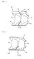
- Figs. 10(a) and (b) are perspective views respectively of a segmented stationary blade unit in the prior art and show state of occurrence of cracks at same time.
- numeral 1a, 1b designates a stationary blade
- numeral 22 designates an outer shroud
- numeral 23 designates an inner shroud.
- Two stationary blades 1a, 1b are fixed in a shroud unit of the outer shroud 22 and the inner shroud 23 so as to form a segment.
- the stationary blades 1a, 1b When the stationary blades 1a, 1b are so constructed in one unit, the stationary blades 1a, 1b and the outer and inner shrouds 22, 23 are mutually restrained so that unreasonable force occurs due to thermal stress and cracks. are liable to occur in an inner side portion P3 of the stationary blade 1a and in a portion S1 of the inner shroud 23, as shown in Fig. 10 (a), and in both end portions P1, P2 of the stationary blade 1a and in a portion S2 of the inner shroud 23, as shown in Fig. 10(b).
- US-A-4 492 517 discloses a gas turbine stationary blade unit with the features of the preamble portion of claim 1.
- US-A-4 015 910 discloses a gas turbine stationary blade unit where both the inner and the outer shrouds are divided and connected by flanges and bolts.
- US-A-5 591 003 discloses a turbine nozzle support structure where only the outer shroud is divided into plural shroud segments.
- a large number of stationary blades are attached to an integrated inner shroud and supported at the outer shroud in that the same is divided into a corresponding number of shroud segments that are connected by pins.
- the present invention provides a gas turbine stationary blade unit as defined in claim 1.
- a preferred embodiment is defined in dependent claim 2.
- the inner and outer shrouds are divided respectively and the divided and mutually adjacent shrouds are connected by the pins, having larger thermal expansion coefficient than the shrouds, inserted in the pinholes provided in the faces of divided portion and are jointed by bolts as fastening members via the flanges formed by the fitting plates being provided along the faces of divided portion and thus the jointed gas turbine stationary blade unit is constructed, hence, by virtue of the divided shrouds of the jointed blade unit, the rigidity of the shrouds is lowered and the temperature distribution is softened and the thermal stress at the blade end portions is mitigated. Further, by virtue of the jointed structure, relative movement between the mutually adjacent shrouds is prevented so that an integrated behavior therebetween is formed and a strong jointed blade unit is obtained.
- FIG. 1 is a perspective view of a gas turbine stationary blade unit of a first example and, as shown there, an outer shroud and an inner shroud are constructed respectively to be divided at a central portion thereof and jointed together by bolts.
- numeral 1a, 1b designates a stationary blade and numeral 2a, 2b designates a divided outer shroud, which fixes the stationary blade 1a, 1b, respectively.
- Numeral 3a, 3b designates a likewise divided inner shroud, which fixes the stationary blade 1a, 1b, respectively.
- the divided portion is a mid portion between the two stationary blades 1a, 1b, as shown in the figure, and there are provided flanges 4a, 4b (not shown) at the divided portions of the divided outer shrouds 2a, 2b, which flanges are jointed together by bolts.
- flanges 5a, 5b are provided at the divided portions of the divided inner shrouds.
- Fig. 2 is a perspective view of a gas turbine stationary blade unit of a second example. While in the first example, both the outer shroud and the inner shroud are divided, only the inner shroud is divided in the second example.
- numeral 1a, 1b designates a stationary blade and numeral 12 designates an outer shroud, which, being not divided, fixes the stationary blade 1a, 1b, respectively.
- Numeral 13a, 13b designates a divided inner shroud and, like in Fig. 1, there are provided flanges 15a, 15b, which are jointed together by bolts.
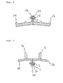
- Fig. 3 is a perspective view of the gas turbine stationary blade unit of the first example of Fig. 1 and shows state of bolt joint at the divided portion of the outer shroud.
- flanges 4a, 4b are provided at divided end portions of the divided outer shrouds 2a, 2b, and boltholes 7 are bored therein so that both the flanges 4a, 4b are jointed together by bolts, that is, the divided portions are jointed together again by bolts.
- flanges 5a, 5b are provided at the divided portions, like in the divided outer shrouds 2a, 2b, and jointed together by bolts.
- Fig. 4 is a cross sectional view taken on line A-A of Fig. 3.
- flanges 4a, 4b are provided to the divided outer shrouds 2a, 2b and boltholes 7 are bored in both of the flanges 4a, 4b so that the flanges 4a, 4b are jointed together by bolts and nuts 6.
- Fig. 5 is a cross sectional view taken on line B-B of Fig. 3.
- flanges 5a, 5b are provided to the divided inner shrouds 3a, 3b so as to project therefrom toward an inner side thereof (toward a rotor side), and like in the divided outer shrouds 2a, 2b, boltholes 7 are bored and the flanges 5a, 5b are jointed together by bolts and nuts 6.
- same flange construction is employed.
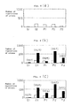
- Fig. 6 is a view of life assessment of crack occurring portions in gas turbine second stage stationary blade units in the prior art and the first and second examples as described above, wherein Fig. 6 (a) shows case of the prior art shown in Fig. 10 where no shroud is divided, Fig. 6(b) shows case of the second example shown in Fig. 2 where only the inner shroud is divided and Fig. 6(c) shows case of the first examples shown in Fig. 1 where both the outer and inner shrouds are divided.
- bar graphs are shown, wherein the crack occurring portions S1, S2, P1, P2 and P3 shown in Figs. 10(a) and (b) are taken on the horizontal axis and number of repetitions of stress is taken on the vertical axis.
- Figs. 6(b) and (c) the number of repetitions of the stress of the second embodiment and the first embodiment, respectively, are shown in black bars and, in comparison thereof, the number of repetitions of the stress of the prior art one is shown in white bars with respect to each of the crack occurring portions, and magnifications of the black bars to the respective white bars are shown in parenthesis.
- life endurance at S2 and P2 becomes 3.9 times and 5.7 times, respectively, of the prior art one and at P3 also, it becomes 8.1 times, hence it is found that the life up to the crack occurrence has elongated remarkably.
- life endurance becomes 3.9 times at S2, 6.7 times at P2 and 11.1 times at P3 and the life up to the crack occurrence has elongated more than the case where the one shroud only is. divided.
- the stationary blade unit is constructed such that both the outer shroud and the inner shroud are divided or only the inner shroud is divided and flanges 4a, 4b and 5a, 5b or 15a, 15b are provided to the divided portions and are jointed together by the bolts and nuts 6, thereby same function as that of the segmented structure consisting of two stationary blades is maintained as it is and moreover frequency of crack occurrence due to the local stress concentration can be lessened greatly.
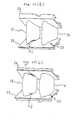
- Fig. 7 is a perspective view of an assembly unit of gas turbine stationary blades of the embodiment
- Fig. 8 is an explanatory view showing one divided portion of the assembly unit of Fig. 7 being divided into two parts
- Fig. 9 is an explanatory view showing details of support pins, fitting plates, etc. in a flange portion of the assembly unit of Fig. 7.
- an inner shroud 101 and an outer shroud 102 are divided into two parts, respectively, at a face of divided portion 109 which extends substantially in an axial direction of turbine, so that the assembly unit is divided into two shroud portions, that is, a portion jointing a stationary blade 103 and a portion jointing a stationary blade 104 which is adjacent to the stationary blade 103.
- pinholes 111 are bored extending in a tangential direction of turbine rotation, so that both pinholes 111 bored in the respective faces of divided portion 109 of the two shroud portions are connected to each other.
- Support pins 106 are inserted into the pinholes 111 to thereby connect the divided two shroud portions.
- the support pins 106 are made of hastelloy material of which thermal expansion coefficient corresponds to 16 to 20 ⁇ 10 -6 /°C and the inner shroud 101 and the outer shroud 102 are made of nickel base heat resistant alloy of which thermal expansion coefficient corresponds to 12 to 16 ⁇ 10 -6 /°C.
- seal grooves 112 which connect to each other in the respective faces of divided portion 109 of the mutually adjacent shroud portions, and seal plates 108 are fitted in the seal grooves 112, thus sealing ability at the faces of divided portion 109 is ensured.
- fitting plates are fixed by welding 110 to form flanges 105 and the respective flanges 105 of the mutually adjacent shroud portions are jointed together by bolts 107 as fastening means.
- the inner shroud 101 is divided into the inner shroud 101 portion of the blade 103 and the inner shroud 101 portion of the blade 104
- the outer shroud 102 is divided into the outer shroud 102 portion of the blade 103 and the outer shroud 102 portion of the blade 104
- the inner shroud 101 portions respectively of the blade 103 and the blade 104 as well as the outer shroud 102 portions respectively of the blade 103 and the blade 104 are jointed by fitting the support pins 106 in the pinholes 111 in the faces of divided portion 109.
- the flanges 105 fixed by welding on the inner and outer sides of the respective faces of divided portion 109, are jointed together by the bolts 107.
- a jointed blade unit consisting of the blade 103 and the blade 104 is constructed.
- the inner shroud 101 and the outer shroud 102 are divided, respectively, as mentioned above, hence the rigidity of the shrouds lowers, the temperature distribution becomes softened, deformation of the shrouds of warp or the like becomes smaller and forces acting on the blades become smaller, thereby alleviation of the thermal stress can be attained.
- the seal plates 108 which ensure the sealing between these faces.
- the pinholes 111 and the support pins 106 which have larger thermal expansion coefficient than the shrouds are inserted therein, hence, due to difference in the thermal elongation between the material of the support pins 106 and the material of the shrouds in which the pinholes 111 are bored, there acts surface pressure between the support pins 106 and the pinholes 111, which prevents relative displacement between the support pins 106 and the shrouds so that an integrated behavior therebetween is formed, thus the burden of the bolts 107 which joint the flanges 105 is mitigated remarkably and soundness of this jointed blade unit is enhanced greatly.
Landscapes
- Engineering & Computer Science (AREA)
- Mechanical Engineering (AREA)
- General Engineering & Computer Science (AREA)
- Turbine Rotor Nozzle Sealing (AREA)
Description
Claims (2)
- A gas turbine stationary blade unit built in a segment such that two stationary blades (103,104) arranged around a turbine rotor are fixed at their respective end portions to an outer shroud and an inner shroud and said outer and said inner shroud or only said inner shroud are/is divided between said two stationary blades (103,104) into adjacent shroud parts (101,102),
wherein flanges (105) are provided to so divided end portions of said shroud parts (101,102) to be jointed together by bolts (107),
wherein adjacent divided shroud parts (101,102) are connected to form a jointed blade unit such that pinholes (111) extending in a turbine rotation tangential direction are provided in respective faces of said divided shroud parts (101,102) extending in a turbine axial direction, and pins (106) are inserted into said pinholes (111) so as to connect the divided and mutually adjacent shroud parts (101,102), characterized in that said pins have a thermal expansion coefficient that is larger than that of the shroud parts (101,102). - The gas turbine stationary blade unit as claimed in claim 1, wherein seal grooves (112) are provided in said respective faces of said adjacent shroud parts (101,102) so as to connect to each other and a seal plate (108) is fitted in the seal grooves (112).
Applications Claiming Priority (6)
| Application Number | Priority Date | Filing Date | Title |
|---|---|---|---|
| JP252098/97 | 1997-09-17 | ||
| JP25209897A JPH1193609A (en) | 1997-09-17 | 1997-09-17 | Gas turbine stationery blade |
| JP25209897 | 1997-09-17 | ||
| JP289821/97 | 1997-10-22 | ||
| JP28982197A JPH11125102A (en) | 1997-10-22 | 1997-10-22 | Gas turbine stator blade |
| JP28982197 | 1997-10-22 |
Publications (3)
| Publication Number | Publication Date |
|---|---|
| EP0903467A2 EP0903467A2 (en) | 1999-03-24 |
| EP0903467A3 EP0903467A3 (en) | 2000-07-12 |
| EP0903467B1 true EP0903467B1 (en) | 2004-07-07 |
Family
ID=26540545
Family Applications (1)
| Application Number | Title | Priority Date | Filing Date |
|---|---|---|---|
| EP98117271A Expired - Lifetime EP0903467B1 (en) | 1997-09-17 | 1998-09-11 | Paired stator vanes |
Country Status (4)
| Country | Link |
|---|---|
| US (1) | US6050776A (en) |
| EP (1) | EP0903467B1 (en) |
| CA (1) | CA2246969C (en) |
| DE (1) | DE69824925T2 (en) |
Families Citing this family (33)
| Publication number | Priority date | Publication date | Assignee | Title |
|---|---|---|---|---|
| CA2231986A1 (en) * | 1997-01-10 | 1999-09-12 | Masahito Kataoka | Stationary blade of integrated segment construction and manufacturing method therefor |
| US6343912B1 (en) * | 1999-12-07 | 2002-02-05 | General Electric Company | Gas turbine or jet engine stator vane frame |
| JP3782637B2 (en) | 2000-03-08 | 2006-06-07 | 三菱重工業株式会社 | Gas turbine cooling vane |
| DE10051223A1 (en) | 2000-10-16 | 2002-04-25 | Alstom Switzerland Ltd | Connectable stator elements |
| JP4508482B2 (en) * | 2001-07-11 | 2010-07-21 | 三菱重工業株式会社 | Gas turbine stationary blade |
| US7651319B2 (en) * | 2002-02-22 | 2010-01-26 | Drs Power Technology Inc. | Compressor stator vane |
| US7101150B2 (en) * | 2004-05-11 | 2006-09-05 | Power Systems Mfg, Llc | Fastened vane assembly |
| US7229245B2 (en) * | 2004-07-14 | 2007-06-12 | Power Systems Mfg., Llc | Vane platform rail configuration for reduced airfoil stress |
| EP1707743A1 (en) * | 2005-03-18 | 2006-10-04 | Siemens Aktiengesellschaft | Segment with minimum two blades, turbine element and method to mount a segment |
| FR2902843A1 (en) | 2006-06-23 | 2007-12-28 | Snecma Sa | COMPRESSOR RECTIFIER AREA OR TURBOMACHINE DISTRIBUTOR SECTOR |
| US7837435B2 (en) * | 2007-05-04 | 2010-11-23 | Power System Mfg., Llc | Stator damper shim |
| US8220150B2 (en) | 2007-05-22 | 2012-07-17 | United Technologies Corporation | Split vane cluster repair method |
| US8511982B2 (en) * | 2008-11-24 | 2013-08-20 | Alstom Technology Ltd. | Compressor vane diaphragm |
| US8371810B2 (en) | 2009-03-26 | 2013-02-12 | General Electric Company | Duct member based nozzle for turbine |
| ITTO20090522A1 (en) * | 2009-07-13 | 2011-01-14 | Avio Spa | TURBOMACCHINA WITH IMPELLER WITH BALLED SEGMENTS |
| US11563389B2 (en) * | 2010-07-30 | 2023-01-24 | Danfoss Customised Power Electronics | Method for starting a single-phase induction motor |
| US8894365B2 (en) * | 2011-06-29 | 2014-11-25 | United Technologies Corporation | Flowpath insert and assembly |
| US20130011265A1 (en) * | 2011-07-05 | 2013-01-10 | Alstom Technology Ltd. | Chevron platform turbine vane |
| US8834109B2 (en) * | 2011-08-03 | 2014-09-16 | United Technologies Corporation | Vane assembly for a gas turbine engine |
| US9127568B2 (en) * | 2012-01-04 | 2015-09-08 | General Electric Company | Turbine casing |
| WO2015023324A2 (en) | 2013-04-12 | 2015-02-19 | United Technologies Corporation | Stator vane platform with flanges |
| JP5717904B1 (en) * | 2014-08-04 | 2015-05-13 | 三菱日立パワーシステムズ株式会社 | Stator blade, gas turbine, split ring, stator blade remodeling method, and split ring remodeling method |
| US20180112546A1 (en) * | 2015-03-17 | 2018-04-26 | SIEMENS AKTIENGESELLSCHAFTü | Stator vane dampening system usable within a turbine engine |
| US9777594B2 (en) | 2015-04-15 | 2017-10-03 | Siemens Energy, Inc. | Energy damping system for gas turbine engine stationary vane |
| FR3051014B1 (en) * | 2016-05-09 | 2018-05-18 | Safran Aircraft Engines | TURBOMACHINE ASSEMBLY COMPRISING A DISTRIBUTOR, A TURBOMACHINE STRUCTURE ELEMENT, AND A FIXING DEVICE |
| DE102016113912A1 (en) * | 2016-07-28 | 2018-02-01 | Man Diesel & Turbo Se | Guide vane arrangement of a turbomachine |
| KR101937586B1 (en) * | 2017-09-12 | 2019-01-10 | 두산중공업 주식회사 | Vane of turbine, turbine and gas turbine comprising it |
| US11066944B2 (en) * | 2019-02-08 | 2021-07-20 | Pratt & Whitney Canada Corp | Compressor shroud with shroud segments |
| US11092022B2 (en) * | 2019-11-04 | 2021-08-17 | Raytheon Technologies Corporation | Vane with chevron face |
| CN112326433B (en) * | 2020-11-13 | 2021-09-14 | 东北大学 | Static blade adjusting mechanism stress-strain test bed considering temperature influence |
| CN117062968A (en) * | 2021-03-23 | 2023-11-14 | 三菱重工业株式会社 | Gas turbine stator vane assembly, stationary member segment and gas turbine stator vane assembly manufacturing method |
| US11512596B2 (en) | 2021-03-25 | 2022-11-29 | Raytheon Technologies Corporation | Vane arc segment with flange having step |
| JP7591977B2 (en) | 2021-05-31 | 2024-11-29 | 三菱重工業株式会社 | Stationary vane segment, gas turbine, and method for manufacturing stationary vane segment |
Family Cites Families (5)
| Publication number | Priority date | Publication date | Assignee | Title |
|---|---|---|---|---|
| US4015910A (en) * | 1976-03-09 | 1977-04-05 | The United States Of America As Represented By The Secretary Of The Air Force | Bolted paired vanes for turbine |
| US4492517A (en) * | 1983-01-06 | 1985-01-08 | General Electric Company | Segmented inlet nozzle for gas turbine, and methods of installation |
| US4720236A (en) * | 1984-12-21 | 1988-01-19 | United Technologies Corporation | Coolable stator assembly for a gas turbine engine |
| JPH03213602A (en) * | 1990-01-08 | 1991-09-19 | General Electric Co <Ge> | Self cooling type joint connecting structure to connect contact segment of gas turbine engine |
| US5441385A (en) * | 1993-12-13 | 1995-08-15 | Solar Turbines Incorporated | Turbine nozzle/nozzle support structure |
-
1998
- 1998-09-11 EP EP98117271A patent/EP0903467B1/en not_active Expired - Lifetime
- 1998-09-11 DE DE69824925T patent/DE69824925T2/en not_active Expired - Lifetime
- 1998-09-14 US US09/152,797 patent/US6050776A/en not_active Expired - Lifetime
- 1998-09-14 CA CA002246969A patent/CA2246969C/en not_active Expired - Lifetime
Also Published As
| Publication number | Publication date |
|---|---|
| EP0903467A3 (en) | 2000-07-12 |
| US6050776A (en) | 2000-04-18 |
| CA2246969A1 (en) | 1999-03-17 |
| CA2246969C (en) | 2002-06-11 |
| DE69824925T2 (en) | 2005-08-25 |
| DE69824925D1 (en) | 2004-08-12 |
| EP0903467A2 (en) | 1999-03-24 |
Similar Documents
| Publication | Publication Date | Title |
|---|---|---|
| EP0903467B1 (en) | Paired stator vanes | |
| EP0384166B1 (en) | Compressor diaphragm assembly | |
| US6471213B1 (en) | Seal structure for gas turbine | |
| JP4130581B2 (en) | Auxiliary seal for string hinge seal in gas turbine | |
| US4492517A (en) | Segmented inlet nozzle for gas turbine, and methods of installation | |
| US3975114A (en) | Seal arrangement for turbine diaphragms and the like | |
| EP1106784B1 (en) | Turbine stator vane frame | |
| JP4268800B2 (en) | Auxiliary seal for string hinge seal in gas turbine | |
| US20090191053A1 (en) | Diaphragm and blades for turbomachinery | |
| US6971844B2 (en) | Horizontal joint sealing system for steam turbine diaphragm assemblies | |
| JPH07111124B2 (en) | Nozzle seal device | |
| US20090191050A1 (en) | Sealing band having bendable tang with anti-rotation in a turbine and associated methods | |
| CA1283609C (en) | Thermal distortion isolation system for turbine blade rings | |
| EP1132576B1 (en) | Turbine shroud comprising an apparatus for minimizing thermal gradients and method for assembling a gas turbine engine including such a shroud | |
| US6719295B2 (en) | Supplemental seal for the chordal hinge seals in a gas turbine | |
| EP1323957B1 (en) | Composite tubular woven seal for gas turbine nozzle and shroud interface | |
| EP1323892B1 (en) | Turbine with a supplemental seal for the chordal hinge seal and method of installation | |
| EP1219783A2 (en) | Stator vane for an axial flow turbine | |
| EP1387042B1 (en) | Steam turbine packing casing horizontal joint seals and methods of forming the seals | |
| EP1751401A2 (en) | Heat shield for gas turbine engine | |
| JPH10159503A (en) | Car cabin sealing device | |
| US5104288A (en) | Dual plane bolted joint for separately-supported segmental stationary turbine blade assemblies | |
| JP4436273B2 (en) | Turbine partition plate and turbine provided with the same | |
| EP0949404A1 (en) | Segmented cascade made from individual vanes which are bolted together | |
| Care | Hoyland et al. |
Legal Events
| Date | Code | Title | Description |
|---|---|---|---|
| PUAI | Public reference made under article 153(3) epc to a published international application that has entered the european phase |
Free format text: ORIGINAL CODE: 0009012 |
|
| 17P | Request for examination filed |
Effective date: 19981008 |
|
| AK | Designated contracting states |
Kind code of ref document: A2 Designated state(s): CH DE FR GB IT LI |
|
| AX | Request for extension of the european patent |
Free format text: AL;LT;LV;MK;RO;SI |
|
| PUAL | Search report despatched |
Free format text: ORIGINAL CODE: 0009013 |
|
| AK | Designated contracting states |
Kind code of ref document: A3 Designated state(s): AT BE CH CY DE DK ES FI FR GB GR IE IT LI LU MC NL PT SE |
|
| AX | Request for extension of the european patent |
Free format text: AL;LT;LV;MK;RO;SI |
|
| AKX | Designation fees paid |
Free format text: CH DE FR GB IT LI |
|
| 17Q | First examination report despatched |
Effective date: 20020425 |
|
| GRAP | Despatch of communication of intention to grant a patent |
Free format text: ORIGINAL CODE: EPIDOSNIGR1 |
|
| GRAS | Grant fee paid |
Free format text: ORIGINAL CODE: EPIDOSNIGR3 |
|
| GRAA | (expected) grant |
Free format text: ORIGINAL CODE: 0009210 |
|
| AK | Designated contracting states |
Kind code of ref document: B1 Designated state(s): CH DE FR GB IT LI |
|
| PG25 | Lapsed in a contracting state [announced via postgrant information from national office to epo] |
Ref country code: LI Free format text: LAPSE BECAUSE OF FAILURE TO SUBMIT A TRANSLATION OF THE DESCRIPTION OR TO PAY THE FEE WITHIN THE PRESCRIBED TIME-LIMIT Effective date: 20040707 Ref country code: IT Free format text: LAPSE BECAUSE OF FAILURE TO SUBMIT A TRANSLATION OF THE DESCRIPTION OR TO PAY THE FEE WITHIN THE PRESCRIBED TIME-LIMIT;WARNING: LAPSES OF ITALIAN PATENTS WITH EFFECTIVE DATE BEFORE 2007 MAY HAVE OCCURRED AT ANY TIME BEFORE 2007. THE CORRECT EFFECTIVE DATE MAY BE DIFFERENT FROM THE ONE RECORDED. Effective date: 20040707 Ref country code: FR Free format text: LAPSE BECAUSE OF FAILURE TO SUBMIT A TRANSLATION OF THE DESCRIPTION OR TO PAY THE FEE WITHIN THE PRESCRIBED TIME-LIMIT Effective date: 20040707 Ref country code: CH Free format text: LAPSE BECAUSE OF FAILURE TO SUBMIT A TRANSLATION OF THE DESCRIPTION OR TO PAY THE FEE WITHIN THE PRESCRIBED TIME-LIMIT Effective date: 20040707 |
|
| REG | Reference to a national code |
Ref country code: GB Ref legal event code: FG4D |
|
| REG | Reference to a national code |
Ref country code: CH Ref legal event code: EP |
|
| REF | Corresponds to: |
Ref document number: 69824925 Country of ref document: DE Date of ref document: 20040812 Kind code of ref document: P |
|
| PG25 | Lapsed in a contracting state [announced via postgrant information from national office to epo] |
Ref country code: GB Free format text: LAPSE BECAUSE OF NON-PAYMENT OF DUE FEES Effective date: 20041007 |
|
| REG | Reference to a national code |
Ref country code: CH Ref legal event code: PL |
|
| PLBE | No opposition filed within time limit |
Free format text: ORIGINAL CODE: 0009261 |
|
| STAA | Information on the status of an ep patent application or granted ep patent |
Free format text: STATUS: NO OPPOSITION FILED WITHIN TIME LIMIT |
|
| GBPC | Gb: european patent ceased through non-payment of renewal fee |
Effective date: 20041007 |
|
| 26N | No opposition filed |
Effective date: 20050408 |
|
| EN | Fr: translation not filed | ||
| PGFP | Annual fee paid to national office [announced via postgrant information from national office to epo] |
Ref country code: DE Payment date: 20170905 Year of fee payment: 20 |
|
| REG | Reference to a national code |
Ref country code: DE Ref legal event code: R071 Ref document number: 69824925 Country of ref document: DE |