EP1237596B1 - Seringues, tubulure de seringue et systemes de transfert de fluide - Google Patents
Seringues, tubulure de seringue et systemes de transfert de fluide Download PDFInfo
- Publication number
- EP1237596B1 EP1237596B1 EP00980979A EP00980979A EP1237596B1 EP 1237596 B1 EP1237596 B1 EP 1237596B1 EP 00980979 A EP00980979 A EP 00980979A EP 00980979 A EP00980979 A EP 00980979A EP 1237596 B1 EP1237596 B1 EP 1237596B1
- Authority
- EP
- European Patent Office
- Prior art keywords
- tube
- syringe
- fluid
- connector
- distal end
- Prior art date
- Legal status (The legal status is an assumption and is not a legal conclusion. Google has not performed a legal analysis and makes no representation as to the accuracy of the status listed.)
- Expired - Lifetime
Links
Images


Classifications
-
- A—HUMAN NECESSITIES
- A61—MEDICAL OR VETERINARY SCIENCE; HYGIENE
- A61M—DEVICES FOR INTRODUCING MEDIA INTO, OR ONTO, THE BODY; DEVICES FOR TRANSDUCING BODY MEDIA OR FOR TAKING MEDIA FROM THE BODY; DEVICES FOR PRODUCING OR ENDING SLEEP OR STUPOR
- A61M5/00—Devices for bringing media into the body in a subcutaneous, intra-vascular or intramuscular way; Accessories therefor, e.g. filling or cleaning devices, arm-rests
- A61M5/14—Infusion devices, e.g. infusing by gravity; Blood infusion; Accessories therefor
- A61M5/142—Pressure infusion, e.g. using pumps
- A61M5/145—Pressure infusion, e.g. using pumps using pressurised reservoirs, e.g. pressurised by means of pistons
- A61M5/1452—Pressure infusion, e.g. using pumps using pressurised reservoirs, e.g. pressurised by means of pistons pressurised by means of pistons
- A61M5/14546—Front-loading type injectors
-
- A—HUMAN NECESSITIES
- A61—MEDICAL OR VETERINARY SCIENCE; HYGIENE
- A61M—DEVICES FOR INTRODUCING MEDIA INTO, OR ONTO, THE BODY; DEVICES FOR TRANSDUCING BODY MEDIA OR FOR TAKING MEDIA FROM THE BODY; DEVICES FOR PRODUCING OR ENDING SLEEP OR STUPOR
- A61M5/00—Devices for bringing media into the body in a subcutaneous, intra-vascular or intramuscular way; Accessories therefor, e.g. filling or cleaning devices, arm-rests
- A61M5/14—Infusion devices, e.g. infusing by gravity; Blood infusion; Accessories therefor
- A61M2005/1401—Functional features
- A61M2005/1403—Flushing or purging
-
- A—HUMAN NECESSITIES
- A61—MEDICAL OR VETERINARY SCIENCE; HYGIENE
- A61M—DEVICES FOR INTRODUCING MEDIA INTO, OR ONTO, THE BODY; DEVICES FOR TRANSDUCING BODY MEDIA OR FOR TAKING MEDIA FROM THE BODY; DEVICES FOR PRODUCING OR ENDING SLEEP OR STUPOR
- A61M5/00—Devices for bringing media into the body in a subcutaneous, intra-vascular or intramuscular way; Accessories therefor, e.g. filling or cleaning devices, arm-rests
- A61M5/36—Devices for bringing media into the body in a subcutaneous, intra-vascular or intramuscular way; Accessories therefor, e.g. filling or cleaning devices, arm-rests with means for eliminating or preventing injection or infusion of air into body
- A61M5/38—Devices for bringing media into the body in a subcutaneous, intra-vascular or intramuscular way; Accessories therefor, e.g. filling or cleaning devices, arm-rests with means for eliminating or preventing injection or infusion of air into body using hydrophilic or hydrophobic filters
- A61M5/385—Devices for bringing media into the body in a subcutaneous, intra-vascular or intramuscular way; Accessories therefor, e.g. filling or cleaning devices, arm-rests with means for eliminating or preventing injection or infusion of air into body using hydrophilic or hydrophobic filters using hydrophobic filters
Definitions
- the present invention relates generally to syringes for use with injectors and, more particularly, to syringes, syringe tubing and fluid transfer systems having features that improve the ease of use and efficiency of loading fluid in and ejecting fluid from the syringes.
- U.S. Patent No. 4,006.736 discloses an apparatus for injecting fluid into the vascular system of a human being or an animal.
- U.S. Patent No. 4,677,980 discloses an angiographic injector and syringe wherein the drive member of the injector can be connected to, or disconnected from, the syringe plunger at any point along the travel path of the plunger via a releasable mechanism requiring rotation of the syringe plunger relative to the piston.
- a front-loading syringe and injector system is disclosed in U.S. Patent No. 5,383,858.
- the syringes disclosed in U.S. Patent No. 5,383,858 can be securely front-loaded directly and accurately on the injector or on a pressure jacket attached to the injector, thereby facilitating the loading-unloading operation as compared to prior systems.
- a user To load syringes with contrast fluid, a user typically connects a fill tube to the front nozzle or discharge outlet of the syringe and places the other end of the tube in a bottle or bag of contrast medium or other fluid.
- the plunger of the syringe is retracted (usually by means of the injector piston) to aspirate the contrast into the syringe until the desired amount is loaded into the syringe.
- the fill tube is then typically discarded. Often, contrast or other fluid contained in the fill tube may drip therefrom onto the floor or the injector.
- a connector tube is connected to the discharge outlet of the syringe and the connecting tube is primed (typically by advancing the plunger in the syringe) to eject air from the syringe and the connector tube (i.e., to prevent air from being injected into the patient). While this technique is entirely effective in purging air from the tubing connected to the syringe, it is undesirable to have liquids dispensed from the end of the tube. Often, the liquids dispensed from the end of the tube foul the exterior surface of the tubing or fall onto the floor. When dealing with contrast media. this is particularly undesirable because the media is very sticky and has a tendency to migrate to whatever surface the operator touches after purging the tube.
- the patient end of the connector tube is connected to, for example, a catheter. in a patient.
- the patient end of the connector tube should be maintained in a sterile condition.
- the present invention provides syringes, syringe tubing and a fluid transfer system that reduces the amount of time and vigilance necessary to load the syringe with fluid, such as contrast fluid, to connect the syringe to a patient and to prime the syringe and connector tube assembly.
- the present invention provides a purge tube that is designed to minimize leakage of contrast medium or other fluid therefrom.
- the present invention provides a syringe and connector tube assembly operable to maintain the sterility of the connector tube for subsequent connection to a patient.
- a syringe in a first aspect, includes a body and a plunger disposed therein.
- the body includes a nozzle formed therein and a latch connected thereto or integrally formed thereon for holding a second end of a fill tube.
- the first end of the fill tube is preferably pre-connected to the nozzle.
- a plastic or other sheath is removably disposed around the fill tube between the first and second ends to maintain the fill tube in a clean and/or sterile condition prior to use for filling / loading the syringe with contrast.
- the diameter of the syringe nozzle may be enlarged to provide for increased volumetric fluid flow (and thereby faster fluid filling / loading) into the syringe.
- the internal diameter of the syringe may be increased from 0.1 inches to approximately 0.2 to 0.25 inches.
- the enlarged syringe nozzle may also decrease the formation of air bubbles, which typically occurs during syringe filling, thereby resulting in less air needing to be expelled from the syringe and the connector tubing prior to injection and decreased risk of an inadvertent air injection into a patient.
- the syringe is packaged with the first end of the fill tube pre-connected to the nozzle and the second end held in the latch.
- the sheath preferably covers the fill tube.
- the second end of the fill tube is removed from the latch and the sheath is removed from the fill tube and discarded.
- the second end of the fill tube is then placed in a contrast or other fluid container.
- the plunger of the syringe is retracted to fill the syringe with the fluid in the container. After a sufficient amount of the fluid is aspirated into the syringe, the fill tube may then be disconnected from the syringe and, preferably, discarded.
- a syringe in a second aspect, includes a body and a plunger disposed therein.
- the body includes a nozzle formed therein and at least one hub member connected thereto or integrally formed thereon for holding an end of a connector tube.
- the at least one hub member comprises two hub members disposed on the syringe body.
- the connector tube includes two ends, each end being connected to a respective hub member to retain the connector tube in contact with the syringe.
- the syringe and the connector tube are packaged in a pre-connected condition for ease of use by the customer.
- one end of the connector tube is removed from a hub member and connected to the nozzle of the syringe.
- the second end of the connector tube is removed from the other hub member and held. preferably over a refuse or other container (i.e., to collect any fluid ejected from the connector tube during the priming operation), while the syringe and connector tube is primed to remove air therefrom.
- the second end of the connector tube is replaced on the hub member on the syringe to maintain it in a sterile condition and/or an "out of the way" location until the second or patient end of the connector tube is connected to the patient.
- the connector tube may include one or more tethered caps to prevent the caps from being dropped on the floor or misplaced.
- the caps are used to close the open ends of the connector tube to, for example. prevent dust or other contaminants from entering the connector tube. After the syringe is filled and/or primed, a cap may be placed on the open, patient end of the connector tube to maintain sterility.
- the caps are tethered to the connector tube by a plastic or other member connected between each of the caps and the connector tube.
- a fluid transfer system in a third aspect, includes a syringe. a fluid container and a transfer device for transferring fluid. such as contrast, from the container to the syringe to fill same.
- the transfer device includes a spike for puncturing the seal of the fluid container, a container holder for holding the fluid container on the spike, a valve for allowing fluid to enter the syringe and a syringe support member for aligning the syringe nozzle with the valve.
- the spike of the transfer device is used to pierce the seal of the fluid container.
- the syringe support member of the transfer device is then placed over the nozzle of the syringe.
- the luer tip of the syringe nozzle engages the valve of the transfer device, thereby allowing the contents of the fluid container to flow into the syringe.
- the piston of the injector retracts the plunger of the syringe.
- the container holder functions to maintain the fluid container in contact with the spike and the fluid transfer device as the fluid is transferred from the fluid container to the syringe.
- the syringe support member maintains the nozzle of the syringe aligned and engaged with the valve, which is preferably a check valve.
- the transfer system is disposable.
- a syringe in a fourth aspect, includes a body and a plunger disposed therein.
- the body includes a nozzle formed therein.
- Flexible inlet tubing may be pre-connected or permanently connected to the nozzle of the syringe (or provided separately) to facilitate filling of the syringe prior to a medical procedure.
- the flexible tubing may remain attached to the nozzle of the syringe after filling thereof to reduce waste and the opportunity for contrast or other fluid from dripping from the syringe nozzle or the inlet tubing.
- the present invention provides a purge tube that can be connected to the end of a connector tube that delivers contrast media or other fluid to a patient.
- the purge tube may minimize or eliminate the discharge of contrast media from the end of the connector tube that delivers the media to the patient when the syringe and connector tube assembly is purged.
- the purge tube may collect any discharged liquid from the end of the connector tube that delivers the contrast media to the patient. The purge tube may then be removed from the connector tube and discarded to minimize or eliminate contamination of other surfaces by the liquid captured thereby.
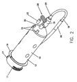
- a syringe 10 includes a body portion 12 and a plunger (not shown) movably disposed therein.
- the body portion 12 defines a nozzle or discharge outlet 16 at the front end thereof for discharging fluid contained within the syringe 10 to a patient and a latch or retention member 24 preferably disposed on a rearward end thereof.
- the body portion 12 further includes at least two mounting flanges 17 and a sealing flange 19 for securely mounting the syringe on the front of an injector (not shown), as disclosed in U.S. Patent No. 5,383,858, the contents of which are hereby incorporated by reference.
- a fill tube 18 includes a first end 20 removably connected to the nozzle 16 of the syringe 10 and a second end 22 removably connected to the latch 24 on the body 12 of the syringe.
- the syringe 10 is preferably packaged in a container (not shown) with the first end 20 of the fill tube 18 pre-connected to the luer tip (not shown) of the nozzle 16 and the second end 22 pre-connected to the latch 24. In that manner. the operator does not have to connect the fill tube 18 to the syringe 10 before filling the syringe with fluid. which is convenient and saves operator time.
- the second end 22 of the fill tube 18 is disconnected from the latch 24 and the sheath 26 is removed from the fill tube 18 (via the free second end 22).
- the second end 22 of the fill tube 18 may then be placed in a fluid container (not shown), such as a contrast container. to fill / load the syringe 10 with fluid.
- the fluid is aspirated into the syringe 10 by retracting the plunger within the syringe 10, preferably by means of the injector piston (not shown).
- the first end 20 of the fill tube 18 can be removed from the nozzle 16 of the syringe 10, and the fill tube 18 discarded.
- a connector tube 28 may be pre-connected to the syringe 10.
- the connector tube 28 includes a first end 30 for connection to the nozzle 16 of the syringe 10 and a second or patient end 32 for connection to a patient (not shown).
- the syringe preferably includes two hub members 34 connected to or formed on the body portion 12 of the syringe.
- the ends 30, 32 of the connector tube 28 are removably connected to a respective hub member 34 on the syringe 10.
- the syringe 10 is preferably packaged with the ends 30, 32 of the connector tube 28 connected to the hub members 34 on the syringe 10.
- the first end 30 of the connector tube 28 is connected to the nozzle 16 of the syringe 10.
- the syringe 10 and the connector tube 28 are then primed to remove air therefrom by advancing the plunger within the syringe 10.
- the air contained within the syringe 10, along with possibly a small amount of fluid, 10 is ejected from the syringe 10 and the second end 32 of the connector tube 28.
- the second end 32 of the tube 28 is reconnected to a hub member 34 until the operator is ready to connect the second end 32 to the patient.
- the second end 32 may be connected to or draped over the latch 24 on the syringe 10.
- the second end 32 of the connector tube 28 may be removed from the patient and reconnected to a hub member 34 to prevent fluid spillage.
- the syringe 10 and connector tube 28 can be disposed of as a unit.
- the connector tube 28 may also include tethered caps 36 for each end 30, 32 thereof.
- the caps 36 may be used to close the open ends 30, 32 of the connector tube 28 to prevent dust and other contaminants from contaminating the connector tube 28 and to prevent fluid from leaking therefrom.
- a cap 36 may be placed over the open, patient end 32 of the connector tube 287 to maintain sterility prior to injection.
- the caps 36 are tethered to the connector tube 28 by means of tethers 38 disposed between the connector tube 28 and the caps 36.
- the tethers 38 may be formed of plastic or any other suitable material.
- a fluid transfer system 40 includes a syringe 42, a fluid container 44 and a transfer device 46 for transferring fluid, such as contrast, from the container 44 to the syringe 42 to fill it.
- the syringe 42 may contain the same features as discussed above with respect to the syringe 10 shown in Figures 1 and 2.
- the transfer device 46 includes a conventional spike 48 for puncturing the seal of the fluid container 44, a container holder or cup 50 for holding the fluid container 44 on the spike 48, a valve (not shown), such as a check valve, for allowing fluid to enter the syringe 42 and a syringe support member or sleeve 54 for holding the syringe 42 in relationship to the transfer device 46.
- a valve such as a check valve
- the plunger (not shown) is advanced to expel air from the syringe 42.
- the syringe 42 is then ready to be filled with fluid.
- the transfer device 46 may then be inserted onto the fluid container 44 such that the spike 48 pierces the seal of the fluid container 44.
- the syringe support member 54 of the transfer device 46 may then be placed over the nozzle of the syringe 42.
- the luer tip 56 of the syringe 42 engages and actuates the valve to open a passage for fluid to flow from the container 44 to the syringe 42.
- the injector piston retracts the plunger (not shown) of the syringe 42.
- the container holder 50 and the syringe support member 54 are designed to impart rigidity to the system and to maintain the syringe 42 and the container 44 in contact with the transfer device 46.
- the transfer system 46 is disposable.
- the syringe 100 includes a cylindrical body 112 and a frusto-conical forward end 114 that transitions into a discharge end 116.
- a flexible inlet tube 118 is connected to the discharge end 116.
- the flexible tube 118 contains a flexible (or corrugated) section 120 disposed between two smooth (or non-corrugated) sections 122, 124.
- Flexible tubing 118 may be composed of any suitable polymeric material so long as the material is flexible, durable. and suitable for medical use.
- flexible tubing 118 is illustrated with two smooth sections 122, 124 connected to one another by a corrugated section 120, other alternative constructions are contemplated within the scope of the present invention.
- the flexible tube may include one corrugated section and one smooth (non-corrugated) section.
- the flexible tube may not include any corrugated sections at all. but instead, may incorporate some other alternative flexible section or sections to accomplish the same objective.
- Flexible tubing 118 may be releasably connected to discharge or dispensing end 116 of syringe 110 or it may be permanently attached thereto. Similarly, flexible tubing 118 may be supplied with syringe 110 or it may be supplied separately and used with syringe 110. As can be readily appreciated, the flexible nature of inlet tube 118 allows it to be easily maneuvered for use with fluid bags or bottles to fill the syringe 110.
- a luer lock 126 is provided at the end of flexible tubing 118 opposite to the end connected to dispensing end 116 of syringe 110.
- a low-pressure connector tubing (“LPCT”) may be connected directly to luer lock 126 for connection to the patient.
- Figure 6 illustrates another embodiment of the present invention, which is specifically directed at the filling of syringe 110 from a bottle of contrast medium.
- a tube extension 128 is illustrated that releasably connects to luer lock 126.
- the extension tubing 128 is inserted into the bottle of contrast media for filling syringe 110.
- extension tubing 128 is removed from the bottle, disconnected from luer lock 126, and discarded. After purging, syringe 110 may then be connected to the patient.
- tubing extension 128, which is usually covered with contrast media after syringe 110 is filled, may be discarded to reduce contamination of equipment with contrast media that may remain thereon.
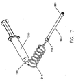
- FIG. 7 illustrates a syringe 210 with a discharge end 212.
- Discharge end 212 is usually provided with a luer lock so that a tube 214, such as a low-pressure connector tubing (or "LPCT”), may be connected thereto.
- LPCT low-pressure connector tubing
- connector tube 124 includes a luer lock 216 at a distal end.
- a purging tube 218 is removably connected to the luer lock 216 of the connector tube 214.
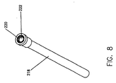
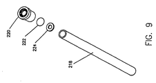
- Purging tube 218, which is shown in detail in Figure 8. has a vented cap 220 at the distal end thereof.
- a flow preventor 222 between purging tube 218 and vented cap 220 are disposed two additional elements, a flow preventor 222 and a seal (or spacer) 224. Seal 224 is disposed between purging tube 218 and flow preventor 222.
- Flow preventor 222 may be any suitable material (including paper) that inhibits the flow of contrast media. but allows air to pass therethrough and out of the end of purging tube 218.
- the vented cap 220 in a preferred embodiment, provides a support structure for the flow preventor 222 and allows air to pass therethrough from the flow preventor 222 to the atmosphere.
- flow preventor 222 is made of Goretex®, which is the trade name of a vapor-breathable fabric made by W.L. Gore and Associates.
- a syringe 210 After a syringe 210 is filled with a fluid, such as a contrast media, the air remaining in the LPCT 214 and the syringe 210 should be purged (e.g., by advancing the syringe plunger) before the LPCT 214 is connected to a patient.
- Purging tube 218 is provided with a sufficiently large interior volume to collect that discharged media.
- the purging tube 218 is adapted to contain approximately 3ml of fluid.
- the purge tube 218 is preferably pre-connected to the distal end of the LPCT 214.
- the vented cap 220 allows air to be discharged from the purge tube 218 and the flow preventor 222 inhibits leakage of contrast media from the distal end of purging tube 218 during the purging operation.
- flow preventor 222 does inhibit the flow of fluid therethrough, it will not prevent fluid flow if a sufficient volume of fluid is discharged into the purge tube 218. Therefore, during the purging operation, an operator should be careful not to discharge into the purge tube 218 more fluid than the fluid volume capacity of the purge tube 218.
- the distal end of the purge tube 218 is preferably held in an elevated position (i.e., opposite from the ground) to further prevent fluid from being discharged from the purge tube 218.
- the purging operation could be conducted with the distal end of the purge tube 218 held in any orientation.
- the purge tube 218 contains the fluid discharged from the syringe 210 and the connector tubing 214.
- the proximal end of the purge tube 218 is preferably elevated prior to or immediately after being disconnected from the connector tube 214. Thereafter, the purge tube 218 is preferably discarded and the connector tube 214 is connected to a catheter in a patient for an injection procedure.
- Purging tube 218 offers at least one further advantage.
- purging tube 218 it is possible to design an injector that has an automatic purge feature. See, for example, the auto prime feature described in PCT International Application No. PCT/US00/31991, filed on November 21, 2000.
- the injector (not shown) may have a button that the practitioner may push to clear air from syringe 210 and the LPCT 214.
- the injector Upon actuation of the auto purge feature, the injector would advance the plunger in the syringe by a predetermined amount.
- the auto purge feature should not exceed the interior volume of the purging tube 218.
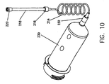
- FIG 10 illustrates the purging tube 218 of the present invention in use with a syringe 230 having a discharge end 232.
- Syringe 230 may be of the type typically used for the injection of contrast media into a patient for vascular imaging, for example. While syringe 230 differs from syringe 210 shown in Figure 7, in all other respects the use and function of purging tube 218 is the same as described above.
- the vented cap 220 and the flow preventor 222 may be positioned at a location between the proximal and distal ends of the purge tube 218.
- the fluid When fluid is discharged into the purge tube 218 past the vented cap 220 and the flow preventor 222 (i.e., to the distal side thereof) during the purging operation, the fluid will cooperate with the flow preventor 222 to prevent the fluid from leaking from the proximal and distal ends of the purge tube 218 after the purge tube 218 is disconnected from the connector tube 214.
- This alternate design may reduce the need for the operator to elevate the proximal end of the purge tube 218 prior to or immediately after it is disconnected from the connector tube 218, as discussed above with respect to the preferred embodiment.
- the vented cap 220 and flow preventor 222 may be replaced with a one-way check valve (not shown) that is biased in a closed position. During the purging operation, the check valve would be forced open to allow air to pass therethrough. After the purging operation is completed, the check valve will close and, when the purge tube 218 is disconnected from the LPCT 214, operate to prevent fluid from leaking from the proximal and distal ends of the purge tube 218.
- tube is not limiting and should be construed to include all suitable types of structures and containers for retaining the discharged fluid from the syringe and the LPCT 214.
Landscapes
- Health & Medical Sciences (AREA)
- Vascular Medicine (AREA)
- Engineering & Computer Science (AREA)
- Anesthesiology (AREA)
- Biomedical Technology (AREA)
- Heart & Thoracic Surgery (AREA)
- Hematology (AREA)
- Life Sciences & Earth Sciences (AREA)
- Animal Behavior & Ethology (AREA)
- General Health & Medical Sciences (AREA)
- Public Health (AREA)
- Veterinary Medicine (AREA)
- Infusion, Injection, And Reservoir Apparatuses (AREA)
Claims (13)
- Assemblage de seringue comprenant :caractérisé parun corps de seringue (210, 230) définissant une extrémité d'évacuation (212, 232) ;un piston disposé de manière mobile à l'intérieur du corps de la seringue ; etun tube de raccordement (214) comprenant une extrémité distale et une première extrémité reliée à l'extrémité d'évacuation du corps de la seringue ;
un tube (218) adapté pour être relié à l'extrémité distale du tube de raccordement (214) pour recueillir le liquide expulsé du corps de la seringue et du tube de raccordement durant une opération de purge, dans lequel le tube (218) comprend :un embout de purge (220) disposé entre une extrémité distale et une extrémité proximale du tube ; etun élément de blocage du débit (222) associé de manière à fonctionner avec l'embout de purge (220), l'élément de blocage du débit pouvant fonctionner de manière à permettre à l'air de passer à travers celui-ci et d'empêcher sensiblement la sortie du liquide du tube et l'embout de purge (220) étant adapté pour permettre à l'air de passer à travers celui-ci à partir de l'élément de blocage du débit vers l'atmosphère. - Assemblage de seringue selon la revendication 1, dans lequel l'embout de purge (220) est disposé au niveau d'une extrémité distale du tube et l'élément de blocage du débit (222) est disposé entre l'embout de purge et le tube.
- Assemblage de seringue selon la revendication 1, dans lequel l'extrémité distale du tube de raccordement comprend un raccordement Luer.
- Assemblage de seringue selon la revendication 1, dans lequel l'extrémité distale du tube de raccordement peut être reliée au cathéter d'un patient.
- Assemblage de seringue selon la revendication 1, dans lequel le tube est pré-relié au tube de raccordement.
- Assemblage de seringue selon la revendication 1, dans lequel le liquide purgé à partir de la seringue est retenu à l'intérieur du tube.
- Assemblage de seringue selon la revendication 6, dans lequel le tube est adapté pour contenir approximativement 3 ml de liquide.
- Assemblage de seringue selon la revendication 2, comprenant en outre un joint (224) disposé entre l'extrémité distale du tube et l'élément de blocage du débit (222) pour empêcher en outre que le liquide ne sorte du tube.
- Assemblage de seringue selon la revendication 1, dans lequel le tube comprend en outre un clapet antiretour.
- Procédé pour purger l'air à partir d'un assemblage de seringue selon l'une quelconque des revendications 1 à 9, comprenant :le raccordement du tube (218) à l'extrémité distale du tube de raccordement, le tube fonctionnant pour recueillir le liquide expulsé du corps de la seringue et du tube de raccordement durant une opération de purge ;le fait d'avancer le piston pour purger l'air du corps de la seringue et du tube de raccordement ; etle fait de recueillir le liquide expulsé du corps de la seringue et du tube de raccordement dans le tube.
- Procédé selon la revendication 10, comprenant en outre :la déconnexion du tube (218) du tube de raccordement ; etla mise au rebut du tube (218).
- Procédé selon la revendication 10, comprenant en outre le raccordement de l'extrémité distale du tube de raccordement au cathéter d'un patient.
- Procédé selon la revendication 10, comprenant en outre l'élévation de l'extrémité distale du tube de purge pour empêcher que le liquide ne fuisse de celui-ci.
Applications Claiming Priority (7)
| Application Number | Priority Date | Filing Date | Title |
|---|---|---|---|
| US16941399P | 1999-12-07 | 1999-12-07 | |
| US169413P | 1999-12-07 | ||
| US22954800P | 2000-09-05 | 2000-09-05 | |
| US22954900P | 2000-09-05 | 2000-09-05 | |
| US229548P | 2000-09-05 | ||
| US229549P | 2000-09-05 | ||
| PCT/US2000/033009 WO2001041835A2 (fr) | 1999-12-07 | 2000-12-06 | Seringues, tubulure de seringue et systemes de transfert de fluide |
Publications (2)
| Publication Number | Publication Date |
|---|---|
| EP1237596A2 EP1237596A2 (fr) | 2002-09-11 |
| EP1237596B1 true EP1237596B1 (fr) | 2004-06-16 |
Family
ID=27389649
Family Applications (1)
| Application Number | Title | Priority Date | Filing Date |
|---|---|---|---|
| EP00980979A Expired - Lifetime EP1237596B1 (fr) | 1999-12-07 | 2000-12-06 | Seringues, tubulure de seringue et systemes de transfert de fluide |
Country Status (7)
| Country | Link |
|---|---|
| US (1) | US6733477B2 (fr) |
| EP (1) | EP1237596B1 (fr) |
| JP (1) | JP2003516192A (fr) |
| CN (1) | CN1174780C (fr) |
| AU (1) | AU1816701A (fr) |
| DE (1) | DE60011670T2 (fr) |
| WO (1) | WO2001041835A2 (fr) |
Families Citing this family (93)
| Publication number | Priority date | Publication date | Assignee | Title |
|---|---|---|---|---|
| US8082018B2 (en) * | 1995-04-20 | 2011-12-20 | Acist Medical Systems, Inc. | System and method for multiple injection procedures on heart vessels |
| US6656157B1 (en) * | 1995-04-20 | 2003-12-02 | Acist Medical Systems, Inc. | Infinitely refillable syringe |
| US7267666B1 (en) * | 1995-04-20 | 2007-09-11 | Acist Medical Systems, Inc. | Angiographic injector system with multiple processor redundancy |
| US6099502A (en) * | 1995-04-20 | 2000-08-08 | Acist Medical Systems, Inc. | Dual port syringe |
| US20030028145A1 (en) * | 1995-04-20 | 2003-02-06 | Duchon Douglas J. | Angiographic injector system with multiple processor redundancy |
| ATE386562T1 (de) * | 1997-11-07 | 2008-03-15 | Acist Medical Sys Inc | Angiographie-spritze mit mehrfachredundanten prozessoren |
| AU4185600A (en) * | 1999-04-01 | 2000-10-23 | Acist Medical Systems, Inc. | An integrated medical information management and medical device control system and method |
| US6958053B1 (en) * | 1999-11-24 | 2005-10-25 | Medrad, Inc. | Injector providing drive member advancement and engagement with syringe plunger, and method of connecting a syringe to an injector |
| US6669679B1 (en) | 2000-01-07 | 2003-12-30 | Acist Medical Systems, Inc. | Anti-recoil catheter |
| US6652489B2 (en) | 2000-02-07 | 2003-11-25 | Medrad, Inc. | Front-loading medical injector and syringes, syringe interfaces, syringe adapters and syringe plungers for use therewith |
| US6626862B1 (en) * | 2000-04-04 | 2003-09-30 | Acist Medical Systems, Inc. | Fluid management and component detection system |
| US6673048B1 (en) * | 2000-05-24 | 2004-01-06 | Acist Medical Systems, Inc. | Pressure sleeve assembly |
| AUPQ867900A0 (en) | 2000-07-10 | 2000-08-03 | Medrad, Inc. | Medical injector system |
| ATE551085T1 (de) * | 2000-07-20 | 2012-04-15 | Acist Medical Sys Inc | SPRITZENSTÖßEL-SPERRMECHANISMUS |
| US8909325B2 (en) | 2000-08-21 | 2014-12-09 | Biosensors International Group, Ltd. | Radioactive emission detector equipped with a position tracking system and utilization thereof with medical systems and in medical procedures |
| US8489176B1 (en) | 2000-08-21 | 2013-07-16 | Spectrum Dynamics Llc | Radioactive emission detector equipped with a position tracking system and utilization thereof with medical systems and in medical procedures |
| US8565860B2 (en) | 2000-08-21 | 2013-10-22 | Biosensors International Group, Ltd. | Radioactive emission detector equipped with a position tracking system |
| WO2002064194A1 (fr) * | 2001-02-14 | 2002-08-22 | Acist Medical Systems, Inc. | Systeme injecteur de fluide |
| WO2002064195A2 (fr) * | 2001-02-14 | 2002-08-22 | Acist Medical Systems, Inc. | Systeme de regulation de fluide d'un catheter |
| US6511457B2 (en) * | 2001-05-04 | 2003-01-28 | Garey Thompson | Airless syringe |
| US7308300B2 (en) * | 2001-05-30 | 2007-12-11 | Acist Medical Systems, Inc. | Medical injection system |
| EP1455642A4 (fr) * | 2001-12-07 | 2006-12-27 | Acist Medical Sys Inc | Dispositifs de mesure de basses pressions dans des environnements sous hautes pressions |
| US6880808B2 (en) | 2002-05-03 | 2005-04-19 | Acist Medical Systems, Inc. | Gamma-stable high pressure stopcock |
| US7534872B2 (en) * | 2002-09-27 | 2009-05-19 | Syngen, Inc. | Compositions and methods for the use of FMOC derivatives in DNA/RNA synthesis |
| US7703483B2 (en) * | 2004-06-04 | 2010-04-27 | Acist Medical Systems, Inc. | Peristaltic syringe filling station |
| US7666169B2 (en) | 2003-11-25 | 2010-02-23 | Medrad, Inc. | Syringe and syringe plungers for use with medical injectors |
| USD1031029S1 (en) | 2003-11-25 | 2024-06-11 | Bayer Healthcare Llc | Syringe plunger |
| US7621892B2 (en) * | 2003-12-31 | 2009-11-24 | Mallinckrodt Inc. | Contrast container holder and method to fill syringes |
| US8586932B2 (en) | 2004-11-09 | 2013-11-19 | Spectrum Dynamics Llc | System and method for radioactive emission measurement |
| US9040016B2 (en) | 2004-01-13 | 2015-05-26 | Biosensors International Group, Ltd. | Diagnostic kit and methods for radioimaging myocardial perfusion |
| WO2006051531A2 (fr) | 2004-11-09 | 2006-05-18 | Spectrum Dynamics Llc | Radio-imagerie |
| US8571881B2 (en) | 2004-11-09 | 2013-10-29 | Spectrum Dynamics, Llc | Radiopharmaceutical dispensing, administration, and imaging |
| US7968851B2 (en) | 2004-01-13 | 2011-06-28 | Spectrum Dynamics Llc | Dynamic spect camera |
| WO2007010534A2 (fr) | 2005-07-19 | 2007-01-25 | Spectrum Dynamics Llc | Protocoles d'imagerie |
| US9470801B2 (en) | 2004-01-13 | 2016-10-18 | Spectrum Dynamics Llc | Gating with anatomically varying durations |
| US7176466B2 (en) | 2004-01-13 | 2007-02-13 | Spectrum Dynamics Llc | Multi-dimensional image reconstruction |
| EP1778957A4 (fr) | 2004-06-01 | 2015-12-23 | Biosensors Int Group Ltd | Optimisation de la mesure d'emissions radioactives dans des structures corporelles specifiques |
| US8423125B2 (en) | 2004-11-09 | 2013-04-16 | Spectrum Dynamics Llc | Radioimaging |
| US9943274B2 (en) | 2004-11-09 | 2018-04-17 | Spectrum Dynamics Medical Limited | Radioimaging using low dose isotope |
| US8615405B2 (en) | 2004-11-09 | 2013-12-24 | Biosensors International Group, Ltd. | Imaging system customization using data from radiopharmaceutical-associated data carrier |
| US9316743B2 (en) | 2004-11-09 | 2016-04-19 | Biosensors International Group, Ltd. | System and method for radioactive emission measurement |
| WO2008059489A2 (fr) | 2006-11-13 | 2008-05-22 | Spectrum Dynamics Llc | Application à la radioimagerie de nouvelles formules de téboroxime |
| US8837793B2 (en) | 2005-07-19 | 2014-09-16 | Biosensors International Group, Ltd. | Reconstruction stabilizer and active vision |
| WO2007076463A2 (fr) * | 2005-12-27 | 2007-07-05 | Acist Medical Systems, Inc. | Dispositif de gonflement de ballonnet |
| US7813841B2 (en) * | 2006-03-10 | 2010-10-12 | Ottawa Heart Institute Research Corporation | Rubidium elution system control |
| US8926569B2 (en) | 2006-03-15 | 2015-01-06 | Bayer Medical Care Inc. | Plunger covers and plungers for use in syringes and methods of fabricating plunger covers and plungers for use in syringes |
| US8894974B2 (en) | 2006-05-11 | 2014-11-25 | Spectrum Dynamics Llc | Radiopharmaceuticals for diagnosis and therapy |
| US9275451B2 (en) | 2006-12-20 | 2016-03-01 | Biosensors International Group, Ltd. | Method, a system, and an apparatus for using and processing multidimensional data |
| USD847985S1 (en) | 2007-03-14 | 2019-05-07 | Bayer Healthcare Llc | Syringe plunger cover |
| USD1002840S1 (en) | 2007-03-14 | 2023-10-24 | Bayer Healthcare Llc | Syringe plunger |
| USD942005S1 (en) | 2007-03-14 | 2022-01-25 | Bayer Healthcare Llc | Orange syringe plunger cover |
| US8521253B2 (en) | 2007-10-29 | 2013-08-27 | Spectrum Dynamics Llc | Prostate imaging |
| US20090118628A1 (en) * | 2007-11-01 | 2009-05-07 | Triage Wireless, Inc. | System for measuring blood pressure featuring a blood pressure cuff comprising size information |
| ES2430045T3 (es) | 2007-12-19 | 2013-11-18 | Sanofi-Aventis Deutschland Gmbh | Dispositivo de jeringuilla de dos cámaras con membrana permeable a gases |
| US8177749B2 (en) | 2008-05-20 | 2012-05-15 | Avant Medical Corp. | Cassette for a hidden injection needle |
| US8052645B2 (en) | 2008-07-23 | 2011-11-08 | Avant Medical Corp. | System and method for an injection using a syringe needle |
| AU2009249027C1 (en) | 2008-05-20 | 2015-01-22 | Avant Medical Corp. | Autoinjector system |
| US8343098B2 (en) | 2009-06-29 | 2013-01-01 | Acist Medical Systems, Inc. | Method and system for removing air from a flow path of a fluid injection device |
| US8338788B2 (en) | 2009-07-29 | 2012-12-25 | Spectrum Dynamics Llc | Method and system of optimized volumetric imaging |
| CA3145238A1 (fr) | 2011-04-20 | 2012-10-26 | Amgen Inc. | Appareil auto-injecteur |
| CA2849486C (fr) | 2011-09-21 | 2017-12-12 | Bayer Medical Care Inc. | Pompe multi-fluide continue, systeme et procede d'entrainement et d'actionnement |
| CN102526838B (zh) * | 2011-12-31 | 2013-06-12 | 宁波市鄞州云帆工程咨询有限公司 | 真空排气式颈静脉注射器 |
| USD898908S1 (en) | 2012-04-20 | 2020-10-13 | Amgen Inc. | Pharmaceutical product cassette for an injection device |
| USD808010S1 (en) | 2012-04-20 | 2018-01-16 | Amgen Inc. | Injection device |
| CN104379065B (zh) | 2012-05-25 | 2018-07-13 | 阿西斯特医疗系统有限公司 | 流体流量测量系统和方法 |
| US9174003B2 (en) | 2012-09-28 | 2015-11-03 | Bayer Medical Care Inc. | Quick release plunger |
| EP2968760B1 (fr) | 2013-03-15 | 2024-01-03 | Amgen Inc. | Cartouche à médicament, auto-injecteur et système d'auto-injection |
| WO2014143815A2 (fr) | 2013-03-15 | 2014-09-18 | Amgen Inc. | Boîte à médicament, autoinjecteur et système d'autoinjecteur |
| US10201690B2 (en) * | 2013-06-19 | 2019-02-12 | Robert Nutter | Wound injector apparatus |
| US10806852B2 (en) | 2014-03-19 | 2020-10-20 | Bayer Healthcare Llc | System for syringe engagement to an injector |
| RU2709546C2 (ru) | 2014-10-28 | 2019-12-18 | БАЙЕР ХелсКер ЛЛСи | Самоориентирующийся кожух высокого давления и механизм стыковки кожуха высокого давления и инъектора |
| KR20170076744A (ko) | 2014-10-28 | 2017-07-04 | 바이엘 헬쓰케어 엘엘씨 | 자기 배향 압력 자켓 및 압력 자켓 대 주입기 인터페이스 |
| US9199033B1 (en) | 2014-10-28 | 2015-12-01 | Bayer Healthcare Llc | Self-orienting syringe and syringe interface |
| NO2689315T3 (fr) | 2014-10-28 | 2018-04-14 | ||
| WO2016112163A1 (fr) | 2015-01-09 | 2016-07-14 | Bayer Healthcare Llc | Système multiple de distribution de fluide avec ensemble jetable à usages multiples et caractéristiques de celui-ci |
| US9480797B1 (en) | 2015-10-28 | 2016-11-01 | Bayer Healthcare Llc | System and method for syringe plunger engagement with an injector |
| WO2017083622A1 (fr) | 2015-11-13 | 2017-05-18 | Bayer Healthcare Llc | Ensemble seringue emboitée |
| US10898638B2 (en) | 2016-03-03 | 2021-01-26 | Bayer Healthcare Llc | System and method for improved fluid delivery in multi-fluid injector systems |
| EP3538182A1 (fr) * | 2016-11-14 | 2019-09-18 | Bayer Healthcare LLC | Procédés et systèmes de vérification du contenu d'une seringue utilisée pour l'administration de fluide médical |
| FI3565619T3 (fi) | 2017-01-06 | 2023-10-16 | Bayer Healthcare Llc | Ruiskun mäntä, jossa on dynaaminen tiiviste |
| JP7317724B2 (ja) | 2017-08-31 | 2023-07-31 | バイエル・ヘルスケア・エルエルシー | 液注入器システムの容積補償システムおよび方法 |
| WO2019046260A1 (fr) | 2017-08-31 | 2019-03-07 | Bayer Healthcare Llc | Procédé de commande de pression dynamique dans un système d'injecteur de fluide |
| EP3675931B1 (fr) | 2017-08-31 | 2021-08-11 | Bayer Healthcare LLC | Système et procédé d'étalonnage de pression d'injecteur |
| AU2018323442B2 (en) | 2017-08-31 | 2024-06-27 | Bayer Healthcare Llc | Fluid path impedance assessment for improving fluid delivery performance |
| US11786652B2 (en) | 2017-08-31 | 2023-10-17 | Bayer Healthcare Llc | System and method for drive member position and fluid injector system mechanical calibration |
| US11191893B2 (en) | 2018-01-31 | 2021-12-07 | Bayer Healthcare Llc | System and method for syringe engagement with injector |
| DK3758777T3 (da) | 2018-02-27 | 2023-02-27 | Bayer Healthcare Llc | Sprøjtestempelindgrebsmekanisme |
| EP3797399A1 (fr) | 2018-05-23 | 2021-03-31 | ACIST Medical Systems, Inc. | Mesure d'un écoulement à l'aide de données d'image |
| US11529507B2 (en) * | 2018-08-31 | 2022-12-20 | Carefusion 303, Inc. | Intravenous priming cap |
| US10758287B2 (en) | 2018-09-13 | 2020-09-01 | Warsaw Orthopedic, Inc. | Bone material mixing and dispensing devices and methods |
| US11654272B2 (en) * | 2019-09-20 | 2023-05-23 | Carefusion 303, Inc. | One-time priming IV infusion extension set |
| JP2023530475A (ja) | 2020-06-18 | 2023-07-18 | バイエル・ヘルスケア・エルエルシー | 注入器とのシリンジプランジャ係合のためのシステムおよび方法 |
| US11633534B2 (en) | 2020-08-18 | 2023-04-25 | Acist Medical Systems, Inc. | Angiogram injections using electrocardiographic synchronization |
Family Cites Families (21)
| Publication number | Priority date | Publication date | Assignee | Title |
|---|---|---|---|---|
| US4006736A (en) | 1974-11-27 | 1977-02-08 | Medrad, Inc. | Angiographic injector |
| US4226236A (en) * | 1979-05-07 | 1980-10-07 | Abbott Laboratories | Prefilled, vented two-compartment syringe |
| DE3576915D1 (de) | 1984-06-06 | 1990-05-10 | Medrad Inc | Angiographie-injektor und mit diesem verwendbare angiograhie-spritze. |
| US4684363A (en) * | 1984-10-31 | 1987-08-04 | American Hospital Supply Corporation | Rapidly inflatable balloon catheter and method |
| US4793351A (en) * | 1987-06-15 | 1988-12-27 | Mansfield Scientific, Inc. | Multi-lumen balloon catheter |
| US5383848A (en) | 1990-04-12 | 1995-01-24 | Gensia, Inc. | Iontophoretic administration of drugs |
| US5176698A (en) * | 1991-01-09 | 1993-01-05 | Scimed Life Systems, Inc. | Vented dilatation cathether and method for venting |
| US5300031A (en) | 1991-06-07 | 1994-04-05 | Liebel-Flarsheim Company | Apparatus for injecting fluid into animals and disposable front loadable syringe therefor |
| US5356375A (en) | 1992-04-06 | 1994-10-18 | Namic U.S.A. Corporation | Positive pressure fluid delivery and waste removal system |
| US5383858B1 (en) | 1992-08-17 | 1996-10-29 | Medrad Inc | Front-loading medical injector and syringe for use therewith |
| US5439452A (en) | 1994-01-31 | 1995-08-08 | Children's Medical Ventures, Inc. | Limit stop valve infusion device |
| US5447496A (en) * | 1994-04-18 | 1995-09-05 | Bove; Rick L. | Method for inplanting a selected liquid into the colon |
| FR2723002B1 (fr) * | 1994-07-26 | 1996-09-06 | Hospal Ind | Dispositif et procede pour preparer un liquide de traitement par filtration |
| US6190354B1 (en) * | 1994-09-16 | 2001-02-20 | Scimed Life Systems, Inc. | Balloon catheter with improved pressure source |
| DE19601214A1 (de) * | 1995-02-20 | 1996-08-22 | Lang Volker | Vorrichtung zur Abnahme von Blut |
| IT235830Y1 (it) | 1995-04-06 | 2000-07-18 | Borla Ind | "raccordo luer-lock con cappuccio di protezione per linee medicali diinfusione-trasfusione." |
| CA2216944C (fr) | 1995-04-20 | 2007-02-27 | Invasatec, Inc. | Injecteur autopurgeur pour angiographie |
| DE19633530A1 (de) * | 1996-08-20 | 1998-02-26 | Claus H Dr Ing Backes | Medizinisches Hochdruckinjektionssystem |
| US5741227A (en) | 1997-04-11 | 1998-04-21 | Sealfon; Andrew I. | Method of sterile preparation of IV pump syringe |
| DE20023614U1 (de) | 1999-11-24 | 2005-05-19 | Medrad, Inc. | Von vorne zu ladender medizinischer Injektor und Spritzen, Spritzenanschlussstücke, Spritzenadapter und Spritzenkolben zur Verwendung damit |
| US6652489B2 (en) * | 2000-02-07 | 2003-11-25 | Medrad, Inc. | Front-loading medical injector and syringes, syringe interfaces, syringe adapters and syringe plungers for use therewith |
-
2000
- 2000-12-06 AU AU18167/01A patent/AU1816701A/en not_active Abandoned
- 2000-12-06 WO PCT/US2000/033009 patent/WO2001041835A2/fr active IP Right Grant
- 2000-12-06 EP EP00980979A patent/EP1237596B1/fr not_active Expired - Lifetime
- 2000-12-06 US US09/731,108 patent/US6733477B2/en not_active Expired - Lifetime
- 2000-12-06 DE DE60011670T patent/DE60011670T2/de not_active Expired - Fee Related
- 2000-12-06 JP JP2001543179A patent/JP2003516192A/ja active Pending
- 2000-12-06 CN CNB008168091A patent/CN1174780C/zh not_active Expired - Fee Related
Also Published As
| Publication number | Publication date |
|---|---|
| US6733477B2 (en) | 2004-05-11 |
| DE60011670T2 (de) | 2004-10-21 |
| US20020068905A1 (en) | 2002-06-06 |
| CN1407905A (zh) | 2003-04-02 |
| CN1174780C (zh) | 2004-11-10 |
| AU1816701A (en) | 2001-06-18 |
| EP1237596A2 (fr) | 2002-09-11 |
| WO2001041835A3 (fr) | 2002-01-03 |
| DE60011670D1 (de) | 2004-07-22 |
| JP2003516192A (ja) | 2003-05-13 |
| WO2001041835A2 (fr) | 2001-06-14 |
Similar Documents
| Publication | Publication Date | Title |
|---|---|---|
| EP1237596B1 (fr) | Seringues, tubulure de seringue et systemes de transfert de fluide | |
| JP5312990B2 (ja) | 血管造影剤注入器サブアッセンブリ | |
| EP0790842B1 (fr) | Appareil d'injection de colorant pour radiographie | |
| JP4270409B2 (ja) | 限定逆流環流弁 | |
| US6972001B2 (en) | Fluid delivery system having pump systems, check valves and a removable patient interface | |
| JP6647043B2 (ja) | 充填済みの使い捨て注射装置 | |
| KR101751719B1 (ko) | 재사용 가능한 자동-주사기 | |
| CA2937901C (fr) | Systeme jetable multidose | |
| JPH08504354A (ja) | 制限吸引のための挿入装置 | |
| JPH08504352A (ja) | ピストン注射器の後方移動を妨げる機構 | |
| KR20230047387A (ko) | 혈관 조영술 주사기의 피처 | |
| US20030176838A1 (en) | Syringes, syringe tubing and fluid transfer systems | |
| US6083204A (en) | Method and apparatus for gravity-fed intravenous infusion | |
| US20210260275A1 (en) | Multi-use drug delivery device for drugs with insufficinet level of preservatives | |
| WO2024086160A1 (fr) | Ensemble de libération de pression pour ensemble de tubes d'injecteur de fluide | |
| CA2204501A1 (fr) | Appareil et procede d'injection de colorant pour radiographie |
Legal Events
| Date | Code | Title | Description |
|---|---|---|---|
| PUAI | Public reference made under article 153(3) epc to a published international application that has entered the european phase |
Free format text: ORIGINAL CODE: 0009012 |
|
| 17P | Request for examination filed |
Effective date: 20020708 |
|
| AK | Designated contracting states |
Kind code of ref document: A2 Designated state(s): AT BE CH CY DE DK ES FI FR GB GR IE IT LI LU MC NL PT SE TR |
|
| AX | Request for extension of the european patent |
Free format text: AL;LT;LV;MK;RO;SI |
|
| GRAH | Despatch of communication of intention to grant a patent |
Free format text: ORIGINAL CODE: EPIDOS IGRA |
|
| GRAS | Grant fee paid |
Free format text: ORIGINAL CODE: EPIDOSNIGR3 |
|
| GRAA | (expected) grant |
Free format text: ORIGINAL CODE: 0009210 |
|
| AK | Designated contracting states |
Kind code of ref document: B1 Designated state(s): DE FR IT NL |
|
| REF | Corresponds to: |
Ref document number: 60011670 Country of ref document: DE Date of ref document: 20040722 Kind code of ref document: P |
|
| REG | Reference to a national code |
Ref country code: IE Ref legal event code: FG4D |
|
| RAP2 | Party data changed (patent owner data changed or rights of a patent transferred) |
Owner name: MEDRAD, INC. |
|
| LTIE | Lt: invalidation of european patent or patent extension |
Effective date: 20040616 |
|
| PGFP | Annual fee paid to national office [announced via postgrant information from national office to epo] |
Ref country code: FR Payment date: 20041201 Year of fee payment: 5 |
|
| NLT2 | Nl: modifications (of names), taken from the european patent patent bulletin |
Owner name: MEDRAD, INC. |
|
| ET | Fr: translation filed | ||
| PLBE | No opposition filed within time limit |
Free format text: ORIGINAL CODE: 0009261 |
|
| STAA | Information on the status of an ep patent application or granted ep patent |
Free format text: STATUS: NO OPPOSITION FILED WITHIN TIME LIMIT |
|
| 26N | No opposition filed |
Effective date: 20050317 |
|
| PG25 | Lapsed in a contracting state [announced via postgrant information from national office to epo] |
Ref country code: IT Free format text: LAPSE BECAUSE OF NON-PAYMENT OF DUE FEES Effective date: 20051206 |
|
| PG25 | Lapsed in a contracting state [announced via postgrant information from national office to epo] |
Ref country code: FR Free format text: LAPSE BECAUSE OF NON-PAYMENT OF DUE FEES Effective date: 20060831 |
|
| REG | Reference to a national code |
Ref country code: FR Ref legal event code: ST Effective date: 20060831 |
|
| PGFP | Annual fee paid to national office [announced via postgrant information from national office to epo] |
Ref country code: NL Payment date: 20071223 Year of fee payment: 8 |
|
| PGFP | Annual fee paid to national office [announced via postgrant information from national office to epo] |
Ref country code: DE Payment date: 20080131 Year of fee payment: 8 |
|
| NLV4 | Nl: lapsed or anulled due to non-payment of the annual fee |
Effective date: 20090701 |
|
| PG25 | Lapsed in a contracting state [announced via postgrant information from national office to epo] |
Ref country code: DE Free format text: LAPSE BECAUSE OF NON-PAYMENT OF DUE FEES Effective date: 20090701 |
|
| PG25 | Lapsed in a contracting state [announced via postgrant information from national office to epo] |
Ref country code: NL Free format text: LAPSE BECAUSE OF NON-PAYMENT OF DUE FEES Effective date: 20090701 |