EP1237502B1 - Dispositif d'administration a fluage par ballonnet et modele de greffe endovasculaire permettant le deploiement facile - Google Patents
Dispositif d'administration a fluage par ballonnet et modele de greffe endovasculaire permettant le deploiement facile Download PDFInfo
- Publication number
- EP1237502B1 EP1237502B1 EP00963638A EP00963638A EP1237502B1 EP 1237502 B1 EP1237502 B1 EP 1237502B1 EP 00963638 A EP00963638 A EP 00963638A EP 00963638 A EP00963638 A EP 00963638A EP 1237502 B1 EP1237502 B1 EP 1237502B1
- Authority
- EP
- European Patent Office
- Prior art keywords
- prosthesis
- sheath
- polymeric material
- delivery system
- delivery
- Prior art date
- Legal status (The legal status is an assumption and is not a legal conclusion. Google has not performed a legal analysis and makes no representation as to the accuracy of the status listed.)
- Expired - Lifetime
Links
Images


Classifications
-
- A—HUMAN NECESSITIES
- A61—MEDICAL OR VETERINARY SCIENCE; HYGIENE
- A61F—FILTERS IMPLANTABLE INTO BLOOD VESSELS; PROSTHESES; DEVICES PROVIDING PATENCY TO, OR PREVENTING COLLAPSING OF, TUBULAR STRUCTURES OF THE BODY, e.g. STENTS; ORTHOPAEDIC, NURSING OR CONTRACEPTIVE DEVICES; FOMENTATION; TREATMENT OR PROTECTION OF EYES OR EARS; BANDAGES, DRESSINGS OR ABSORBENT PADS; FIRST-AID KITS
- A61F2/00—Filters implantable into blood vessels; Prostheses, i.e. artificial substitutes or replacements for parts of the body; Appliances for connecting them with the body; Devices providing patency to, or preventing collapsing of, tubular structures of the body, e.g. stents
- A61F2/02—Prostheses implantable into the body
- A61F2/04—Hollow or tubular parts of organs, e.g. bladders, tracheae, bronchi or bile ducts
- A61F2/06—Blood vessels
- A61F2/07—Stent-grafts
-
- A—HUMAN NECESSITIES
- A61—MEDICAL OR VETERINARY SCIENCE; HYGIENE
- A61F—FILTERS IMPLANTABLE INTO BLOOD VESSELS; PROSTHESES; DEVICES PROVIDING PATENCY TO, OR PREVENTING COLLAPSING OF, TUBULAR STRUCTURES OF THE BODY, e.g. STENTS; ORTHOPAEDIC, NURSING OR CONTRACEPTIVE DEVICES; FOMENTATION; TREATMENT OR PROTECTION OF EYES OR EARS; BANDAGES, DRESSINGS OR ABSORBENT PADS; FIRST-AID KITS
- A61F2/00—Filters implantable into blood vessels; Prostheses, i.e. artificial substitutes or replacements for parts of the body; Appliances for connecting them with the body; Devices providing patency to, or preventing collapsing of, tubular structures of the body, e.g. stents
- A61F2/95—Instruments specially adapted for placement or removal of stents or stent-grafts
- A61F2/962—Instruments specially adapted for placement or removal of stents or stent-grafts having an outer sleeve
- A61F2/97—Instruments specially adapted for placement or removal of stents or stent-grafts having an outer sleeve the outer sleeve being splittable
-
- A—HUMAN NECESSITIES
- A61—MEDICAL OR VETERINARY SCIENCE; HYGIENE
- A61F—FILTERS IMPLANTABLE INTO BLOOD VESSELS; PROSTHESES; DEVICES PROVIDING PATENCY TO, OR PREVENTING COLLAPSING OF, TUBULAR STRUCTURES OF THE BODY, e.g. STENTS; ORTHOPAEDIC, NURSING OR CONTRACEPTIVE DEVICES; FOMENTATION; TREATMENT OR PROTECTION OF EYES OR EARS; BANDAGES, DRESSINGS OR ABSORBENT PADS; FIRST-AID KITS
- A61F2/00—Filters implantable into blood vessels; Prostheses, i.e. artificial substitutes or replacements for parts of the body; Appliances for connecting them with the body; Devices providing patency to, or preventing collapsing of, tubular structures of the body, e.g. stents
- A61F2/82—Devices providing patency to, or preventing collapsing of, tubular structures of the body, e.g. stents
- A61F2/86—Stents in a form characterised by the wire-like elements; Stents in the form characterised by a net-like or mesh-like structure
- A61F2/89—Stents in a form characterised by the wire-like elements; Stents in the form characterised by a net-like or mesh-like structure the wire-like elements comprising two or more adjacent rings flexibly connected by separate members
-
- A—HUMAN NECESSITIES
- A61—MEDICAL OR VETERINARY SCIENCE; HYGIENE
- A61F—FILTERS IMPLANTABLE INTO BLOOD VESSELS; PROSTHESES; DEVICES PROVIDING PATENCY TO, OR PREVENTING COLLAPSING OF, TUBULAR STRUCTURES OF THE BODY, e.g. STENTS; ORTHOPAEDIC, NURSING OR CONTRACEPTIVE DEVICES; FOMENTATION; TREATMENT OR PROTECTION OF EYES OR EARS; BANDAGES, DRESSINGS OR ABSORBENT PADS; FIRST-AID KITS
- A61F2/00—Filters implantable into blood vessels; Prostheses, i.e. artificial substitutes or replacements for parts of the body; Appliances for connecting them with the body; Devices providing patency to, or preventing collapsing of, tubular structures of the body, e.g. stents
- A61F2/02—Prostheses implantable into the body
- A61F2/04—Hollow or tubular parts of organs, e.g. bladders, tracheae, bronchi or bile ducts
- A61F2/06—Blood vessels
- A61F2/07—Stent-grafts
- A61F2002/072—Encapsulated stents, e.g. wire or whole stent embedded in lining
-
- A—HUMAN NECESSITIES
- A61—MEDICAL OR VETERINARY SCIENCE; HYGIENE
- A61F—FILTERS IMPLANTABLE INTO BLOOD VESSELS; PROSTHESES; DEVICES PROVIDING PATENCY TO, OR PREVENTING COLLAPSING OF, TUBULAR STRUCTURES OF THE BODY, e.g. STENTS; ORTHOPAEDIC, NURSING OR CONTRACEPTIVE DEVICES; FOMENTATION; TREATMENT OR PROTECTION OF EYES OR EARS; BANDAGES, DRESSINGS OR ABSORBENT PADS; FIRST-AID KITS
- A61F2/00—Filters implantable into blood vessels; Prostheses, i.e. artificial substitutes or replacements for parts of the body; Appliances for connecting them with the body; Devices providing patency to, or preventing collapsing of, tubular structures of the body, e.g. stents
- A61F2/02—Prostheses implantable into the body
- A61F2/04—Hollow or tubular parts of organs, e.g. bladders, tracheae, bronchi or bile ducts
- A61F2/06—Blood vessels
- A61F2/07—Stent-grafts
- A61F2002/075—Stent-grafts the stent being loosely attached to the graft material, e.g. by stitching
-
- A—HUMAN NECESSITIES
- A61—MEDICAL OR VETERINARY SCIENCE; HYGIENE
- A61F—FILTERS IMPLANTABLE INTO BLOOD VESSELS; PROSTHESES; DEVICES PROVIDING PATENCY TO, OR PREVENTING COLLAPSING OF, TUBULAR STRUCTURES OF THE BODY, e.g. STENTS; ORTHOPAEDIC, NURSING OR CONTRACEPTIVE DEVICES; FOMENTATION; TREATMENT OR PROTECTION OF EYES OR EARS; BANDAGES, DRESSINGS OR ABSORBENT PADS; FIRST-AID KITS
- A61F2/00—Filters implantable into blood vessels; Prostheses, i.e. artificial substitutes or replacements for parts of the body; Appliances for connecting them with the body; Devices providing patency to, or preventing collapsing of, tubular structures of the body, e.g. stents
- A61F2/95—Instruments specially adapted for placement or removal of stents or stent-grafts
- A61F2002/9505—Instruments specially adapted for placement or removal of stents or stent-grafts having retaining means other than an outer sleeve, e.g. male-female connector between stent and instrument
- A61F2002/9511—Instruments specially adapted for placement or removal of stents or stent-grafts having retaining means other than an outer sleeve, e.g. male-female connector between stent and instrument the retaining means being filaments or wires
-
- A—HUMAN NECESSITIES
- A61—MEDICAL OR VETERINARY SCIENCE; HYGIENE
- A61F—FILTERS IMPLANTABLE INTO BLOOD VESSELS; PROSTHESES; DEVICES PROVIDING PATENCY TO, OR PREVENTING COLLAPSING OF, TUBULAR STRUCTURES OF THE BODY, e.g. STENTS; ORTHOPAEDIC, NURSING OR CONTRACEPTIVE DEVICES; FOMENTATION; TREATMENT OR PROTECTION OF EYES OR EARS; BANDAGES, DRESSINGS OR ABSORBENT PADS; FIRST-AID KITS
- A61F2/00—Filters implantable into blood vessels; Prostheses, i.e. artificial substitutes or replacements for parts of the body; Appliances for connecting them with the body; Devices providing patency to, or preventing collapsing of, tubular structures of the body, e.g. stents
- A61F2/95—Instruments specially adapted for placement or removal of stents or stent-grafts
- A61F2/958—Inflatable balloons for placing stents or stent-grafts
- A61F2002/9583—Means for holding the stent on the balloon, e.g. using protrusions, adhesives or an outer sleeve
-
- A—HUMAN NECESSITIES
- A61—MEDICAL OR VETERINARY SCIENCE; HYGIENE
- A61F—FILTERS IMPLANTABLE INTO BLOOD VESSELS; PROSTHESES; DEVICES PROVIDING PATENCY TO, OR PREVENTING COLLAPSING OF, TUBULAR STRUCTURES OF THE BODY, e.g. STENTS; ORTHOPAEDIC, NURSING OR CONTRACEPTIVE DEVICES; FOMENTATION; TREATMENT OR PROTECTION OF EYES OR EARS; BANDAGES, DRESSINGS OR ABSORBENT PADS; FIRST-AID KITS
- A61F2210/00—Particular material properties of prostheses classified in groups A61F2/00 - A61F2/26 or A61F2/82 or A61F9/00 or A61F11/00 or subgroups thereof
- A61F2210/0004—Particular material properties of prostheses classified in groups A61F2/00 - A61F2/26 or A61F2/82 or A61F9/00 or A61F11/00 or subgroups thereof bioabsorbable
-
- A—HUMAN NECESSITIES
- A61—MEDICAL OR VETERINARY SCIENCE; HYGIENE
- A61F—FILTERS IMPLANTABLE INTO BLOOD VESSELS; PROSTHESES; DEVICES PROVIDING PATENCY TO, OR PREVENTING COLLAPSING OF, TUBULAR STRUCTURES OF THE BODY, e.g. STENTS; ORTHOPAEDIC, NURSING OR CONTRACEPTIVE DEVICES; FOMENTATION; TREATMENT OR PROTECTION OF EYES OR EARS; BANDAGES, DRESSINGS OR ABSORBENT PADS; FIRST-AID KITS
- A61F2230/00—Geometry of prostheses classified in groups A61F2/00 - A61F2/26 or A61F2/82 or A61F9/00 or A61F11/00 or subgroups thereof
- A61F2230/0002—Two-dimensional shapes, e.g. cross-sections
- A61F2230/0028—Shapes in the form of latin or greek characters
- A61F2230/005—Rosette-shaped, e.g. star-shaped
-
- A—HUMAN NECESSITIES
- A61—MEDICAL OR VETERINARY SCIENCE; HYGIENE
- A61F—FILTERS IMPLANTABLE INTO BLOOD VESSELS; PROSTHESES; DEVICES PROVIDING PATENCY TO, OR PREVENTING COLLAPSING OF, TUBULAR STRUCTURES OF THE BODY, e.g. STENTS; ORTHOPAEDIC, NURSING OR CONTRACEPTIVE DEVICES; FOMENTATION; TREATMENT OR PROTECTION OF EYES OR EARS; BANDAGES, DRESSINGS OR ABSORBENT PADS; FIRST-AID KITS
- A61F2250/00—Special features of prostheses classified in groups A61F2/00 - A61F2/26 or A61F2/82 or A61F9/00 or A61F11/00 or subgroups thereof
- A61F2250/0014—Special features of prostheses classified in groups A61F2/00 - A61F2/26 or A61F2/82 or A61F9/00 or A61F11/00 or subgroups thereof having different values of a given property or geometrical feature, e.g. mechanical property or material property, at different locations within the same prosthesis
- A61F2250/0018—Special features of prostheses classified in groups A61F2/00 - A61F2/26 or A61F2/82 or A61F9/00 or A61F11/00 or subgroups thereof having different values of a given property or geometrical feature, e.g. mechanical property or material property, at different locations within the same prosthesis differing in elasticity, stiffness or compressibility
-
- A—HUMAN NECESSITIES
- A61—MEDICAL OR VETERINARY SCIENCE; HYGIENE
- A61F—FILTERS IMPLANTABLE INTO BLOOD VESSELS; PROSTHESES; DEVICES PROVIDING PATENCY TO, OR PREVENTING COLLAPSING OF, TUBULAR STRUCTURES OF THE BODY, e.g. STENTS; ORTHOPAEDIC, NURSING OR CONTRACEPTIVE DEVICES; FOMENTATION; TREATMENT OR PROTECTION OF EYES OR EARS; BANDAGES, DRESSINGS OR ABSORBENT PADS; FIRST-AID KITS
- A61F2250/00—Special features of prostheses classified in groups A61F2/00 - A61F2/26 or A61F2/82 or A61F9/00 or A61F11/00 or subgroups thereof
- A61F2250/0058—Additional features; Implant or prostheses properties not otherwise provided for
- A61F2250/0071—Additional features; Implant or prostheses properties not otherwise provided for breakable or frangible
Definitions
- the present invention relates generally to an endoluminal prosthesis delivery system according to the preamble of claim 1.
- Endoluminal prostheses are typically used to repair, replace, or otherwise correct a diseased or damaged blood vessel.
- An artery or vein may be diseased in a variety of ways.
- the prosthesis may therefore be used to prevent or treat a wide variety of defects such as stenosis of the vessel, thrombosis, occlusion, or an aneurysm.
- a stent is a generally longitudinal tubular device which is useful to open and support various lumens in the body.
- stents may be used in the vascular system, urogenital tract and bile duct, as well as in a variety of other applications in the body.
- Endovascular stents have become widely used for the treament of stenosis, strictures, and aneurysms in various blood vessels. These devices are implanted within the vessel to open and/or reinforce collapsing or partially occluded sections of the vessel.
- Stents are generally open ended and are radially expandable between a generally unexpanded insertion diameter and an expanded implantation diameter which is greater than the unexpanded insertion diameter. Stents are often flexible in configuration, which allows them to be inserted through and conform to tortuous pathways in the blood vessel. The stent is generally inserted in a radially compressed state and expanded either through a self-expanding mechanism, or through the use of balloon catheters.
- a graft is another type of endoluminal prosthesis which is used to repair and replace various body vessels. Whereas a stent provides structural support to hold a damaged vessel open, a graft provides an artificial lumen through which blood may flow. Grafts are tubular devices which may be formed of a variety of materials, including textile and non-textile materials. Grafts also generally have an unexpanded insertion diameter and an expanded implantation diameter which is greater than the unexpanded diameter.
- delivery systems for delivering such prostheses intraluminally.
- These delivery systems generally include catheters with the prosthesis removably mounted to the distal end of the catheter. Quite often a catheter, introducer sheath, or other similar retaining means, is disposed over the prosthesis to removably support the prosthesis on the catheter. Once the prosthesis is situated in the target site in the lumen, the catheter is removed from the prosthesis.
- the catheter typically retains and delivers the prostheses in a radially contracted state in its unexpanded insertion diameter, and removal of the catheter sheath allows expansion to the expanded implantation diameter.
- catheter movement can disturb or move the introducer sheath at the wound site where the catheter is inserted into the vessel, thereby resulting in premature deployment of the prosthesis.
- tortuous anatomy the added friction caused by rubbing the outer catheter against the vessel can make delivery and deployment of the prosthesis difficult.
- the translation of control movements from the proximal to the distal end of the catheter is imprecise, jerky and in some instances impossible due to the increased friction caused by tortuosity.
- delivery of the sheathed prosthesis can create trauma to the endothelium. over the entire length of the catheter.
- EP-A-839506 discloses a composite stent with a restraint sleeve restricting the maximum transverse dimension.
- the stent When the stent is appropriately positioned in the lumen it is expanded into contact with the internal surface of the lumen by means of an inflatable balloon. During this procedure the restraint sleeve is expanded plastically. The fact that the restraint sleeve does not have to be removed prior to deployment of the stent constitutes a significant advantage of this system.
- the present invention may be used in a method of implanting an endoluminal prosthesis comprising loading a tubular endoluminal prosthesis in a reduced diameter in a compressed condition within a delivery sheath, said prosthesis being radially expandable under a first radially expansive force and a second radially expansive force greater than said first radially expansive force, said delivery sheath having a yield strength sufficient to retain said prosthesis in reduced diameter; intraluminally delivering said prosthesis to an implantation site wherein said second radially expansive force of said prosthesis is activated, said second radially expansive force being sufficient to surpass said yield strength of said delivery sheath.
- a radially expansive force may be applied to the prosthesis by a balloon catheter, said radially expansive force being sufficient to surpass said yield strength of said delivery sheath.
- the present invention provides a system for delivery of an expandable prosthesis to a target site.
- the delivery system may include a catheter having an expandable balloon.
- the endoluminal prosthesis is supported over the balloon by a catheter sheath.
- the present invention provides a catheter sheath which has a yield strength greater than a first expansive force exhibited by the endoluminal prosthesis, but less than a second expansive force of either the balloon or of the prosthesis so as to retain the prosthesis in a collapsed condition during delivery and to provide for deployment of the expandable prosthesis upon application of the expansive force from the balloon without removal of the sheath.
- prostheses may be employed in the present invention.
- a stent, vascular graft, stent covered with a graft, or other stent/graft combinations may be employed.
- the prosthesis may be self-expanding, or expandable by other expansion mechanisms, such as balloon expansion.
- the second radially expansive force may be a result of the self-expansion of the prosthesis. and a balloon catheter will not be necessary.
- the term radially expansive force as used in this disclosure refers to the force which may be applied to the tubular prosthesis and/or delivery sheath to provide for circumferential expansion. It could be equal to zero.
- stents which may be employed include, without limitation, self-expanding stents and balloon expandable stents.
- the configuration of the stent may also be chosen from a host of geometries.
- the stents may be capable of radially expanding, as well as contracting, and in this sense can best be described as radially distensible or deformable.
- Self-expanding stents include those that have a spring-like action which causes the stent to radially expand, or stents which expand due to memory properties of the stent material for a particular configuration at a certain temperature.
- Nitinol is one material which has the ability to perform well while both in spring-like mode, as well as in a memory mode based on temperature.
- Other materials are of course contemplated, such as stainless steel, platinum, gold, titanium, and other biocompatible metals, as well as polymeric stents.
- Endovascular grafts may also be used in the present invention.
- endovascular grafts may be used alone or in conjunction with a stent.
- a stent may have an outer tubular cover, inner tubular cover, or both.
- Many other variations of the stent/graft combination, as well as other types of prostheses may also be used with the present invention.
- the delivery system 1 of the present invention includes a delivery catheter 3 having an expandable balloon 2 at one end.
- catheter 3 may be used in delivering a balloon-expandable prosthesis 4.
- the endoluminal prosthesis 4 shown in Figures 1 and 2 is a composite stent/graft device which includes a radially distensible stent 8 with an exterior cover 10, and an interior cover 12.
- prosthesis 4 is expandable from a non-expanded or collapsed delivery configuration to an expanded deployed configuration.
- Prosthesis 4 is radially distensible upon an expansive force. The expansive force may be applied by expansion of balloon 2 or may be derived from self-expansion of the prosthesis itself.
- Delivery catheter sheath 6 is an elongate thin walled tube which surrounds the prosthesis 4 and supports the prosthesis over balloon catheter 2. Sheath 6 retains prosthesis 4 in a non-expanded state during catheter delivery. Such retention of the prosthesis is provided by constructing sheath 6 to have a yield strength which is greater than a first expansive force required to expand prosthesis 4 from its collapsed configuration to its expanded configuration. The yield strength of catheter sheath 6 is therefore sufficiently strong to retain prosthesis 4 in a contracted state on balloon 2 during delivery of the prosthesis.
- the elongate tube forming delivery cathetef sheath 6 may be formed from an extruded tube shown in Figure 1, or from an extruded sheet formed into a tube, as shown in Figure 2.
- catheter sheath 6 While the yield strength of catheter sheath 6 is sufficient to retain prosthesis 4 in a non-expanded configuration during delivery of the prosthesis, the yield strength is sufficiently less than a second expansive force which is applied to prosthesis 4 in order to deploy the prosthesis. This second expansive force is typically derived from the expansion of balloon catheter 2. Catheter sheath 6 is therefore formed in order to provide the yield strength which is sufficient to maintain the prosthesis in a collapsed delivery condition, yet is inelastically expanded upon application of a greater force so as to permit deployment of the prosthesis. A variety of sheath constructions are contemplated within the present invention so that the appropriate yield strength may be imparted to the sheath. More particularly, a material is selected with the desirous yield. strength properties.
- sheath 6 may also be constructed with tubular walls with a particularly thin cross-section appropriate to impart the desirous yield strength. Still further, weak points in the tube may be deliberately introduced to give pre-determined yield points within sheath 6. Sheath 6 is typically formed of a polymeric material by extrusion and stretching techniques commonly known in the art.
- Standard extrusion techniques such as those discussed in U.S. Patent Nos.3,953,566, 3,962.153 and 4,187,390 may be employed.
- Prosthesis 4 is loaded within delivery sheath 6 in a reduced delivery diameter.
- sheath 6 has a yield strength sufficient to retain prosthesis 4 in this reduced diameter.
- An unexpanded balloon catheter is then inserted within prosthesis 4.
- delivery catheter 3 includes an expandable balloon 2 for supporting said prosthesis and is expandable under a radially expansive force.
- the prosthesis 4, sheath 6, and balloon catheter 2 are delivered intraluminally to the implantation site, however, in a contracted state.
- a radially expansive force is applied to balloon catheter 2. This radially expansive force is applied by inflating balloon 2 with a fluid as is well known in the catheter art.
- the applied radially expansive force supplied by balloon expansion is sufficient to surpass the yield strength of sheath 6. This causes the sheath 6 to expand allowing the prosthesis to expand to its expanded position. Sheath 6 therefore allows expansion and implantation of prosthesis 4 with the application of this radially expansive force by its thin tubular walls expanding past their yield strength.
- the initial inelasticity of sheath 6 during delivery allows successful implantation of prosthesis 4.
- the appropriate yield strength of the delivery sheath may be provided in a number of ways. In Figures 1 and 2, the thin walled polymeric material forms the sheath itself and provides the appropriate yield strength.
- yield strength refers to the stress level at which the material can no longer elastically resist permanent deformation. After a material has been stretched beyond a certain point, the material remains fixed in its stretched condition. This type of stretching causes the material to either undergo inelastic strain, commonly referred to as plastic deformation, or it may cause the material to fracture. Often, the material undergoes first inelastic strain, then fracture. In any case, delivery sheath 6 is inelastically expanded and is no longer able to radially restrain prosthesis 4.
- sheath 6 may remain implanted with prosthesis 4 or it may be removed. If it is desired to remain implanted with the prosthesis, sheath 6 may be constructed of material of sufficiently biocompatible properties so it will not interfere with assimilation of the prosthesis in vivo. Such biological assimilation and incorporation includes endothelialization, and other adaptive measures taken by the body in response to the implant.
- Polytetrafluoroethylene is an example of a polymeric material with a microporous structure to allow biologic assimilation.
- the delivery sheath 14 is a tubular body formed of two different polymeric materials.
- Sheath 14 includes a plurality of longitudinally extending segments 16 formed of a first polymeric material intermittently embedded within tubular body 18 of a second polymeric material.
- the first and second polymeric materials of the sheath as well as their shape and construction may be varied according to the desired properties of yield strength in relation to each other.
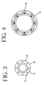
- delivery sheath 17 can be a tube having a circumference and a longitudinal axis, and comprising a first polymeric material and a second polymeric material.
- Said first polymeric material comprises circumferential segments 19 intermittently embedded within said second polymeric material 21 (which is formed into a tubular body) and disposed transverse to said longitudinal axis.
- Circumferential segments 19 may be a continuous helix wrapped circumferentially around said sheath, or segments 19 may be intermittently independent ring segments, each forming a continuous loop circumferentially around said sheath 17.
- first polymeric material 16 (or 19) has a yield or tensile strength greater than that of second polymeric material 18 (or 21). In this embodiment a radially expansive force applied to the sheath will cause the sheath to stretch at the preselected areas occupied by the second polymeric material 18 (or 21). Accordingly, first polymeric material 16 (or 19) will provide strength to the sheath, and prevent axial expansion of the graft.
- first polymeric material 16 (19) possesses a tensile strength less than that of polymeric material 18 (21).
- a radially expansive force applied to the sheath will cause the sheath to stretch at segmented areas of polymeric material 16 (19).
- Second polymeric material 18 (21), in which first polymeric material 16 (19) is embedded will provide structural integrity and strength while the sheath stretches in the preselected areas of longitudinal segments.
- the first polymeric material 16 because it is of lesser tensile strength, provides the yielding area for the sheath.
- the first and second polymeric material may be formed of a variety of material.
- various grades and durometers of the same base resin or composite assemblies of different base resins, as well as any number of combinations or alloys of materials may be used as either material in the sheath.
- Some materials which may be used in the sheath include, but are not limited to nylon (polyamide), polyurethane (PU), polyimide (PI).
- the combination of materials comprising delivery sheath 14 or 17 in Figures 3, 4 and 4A, and their corresponding tensile strengths therefore, provides catheter delivery sheath 14 and 17 with a yield strength greater than a first radially expansive force of prosthesis 15. Similar to the sheath described above in Figures 1 and 2, the yield strength of sheath 14 and 17 is less than that of a second radially expansive force which is either applied by a self-expansion mechanism of the prosthesis, or by the expansion of the balloon to said catheter. Similarly. application of the second expansive force deploys the prosthesis within the lumen. After deployment, catheter sheath 14 may remain implanted within the lumen, or may subsequently be withdrawn.
- a preferred method of making catheter sheath 14 is by co-extrusion of the two polymeric materials together by the above mentioned extrusion techniques.
- a delivery system comprising an endoluminal prosthesis 20, and a catheter delivery sheath 22 is shown.
- Delivery sheath 22 of Figure 4 is comprised of polymeric strips circumferentially wrapped around said prosthesis transversely to a longitudinal axis of said prosthesis.
- Polymeric strips 24 possess a first end 26 and a second end 28.
- First end 26 and second end 28 may abut or overlap to form a circumferential loop around a longitudinal axis of the prosthesis and meet at a selected area of the sheath.
- First end 26 and second end 28 may be adhered together at their meeting point, may be adhesively adhered together at their meeting point, may be adhered to the prosthesis at their meeting point, or may be adhesively adhered to the prosthesis at the meeting point.
- adhered is used to refer to any means of securing components together without the use of an adhesive. Some examples include, thermal bonding, sintering, or, fastening through other mechanical means. Adhesives which may be used vary depend on what type of polymeric material is used as the polymeric strip.
- the polymeric strip may be formed of polytetrafluoroethylene (PTFE), ePTFE, polyurethane, fluorinated ethylene propylene (FEP), polyether ether ketone, polyimide, nylon (polyamide), polybutylene terephthalate as well as other thermoplastic elastomers.
- PTFE polytetrafluoroethylene
- ePTFE polyurethane
- FEP fluorinated ethylene propylene
- polyether ether ketone polyimide
- nylon polyamide
- polybutylene terephthalate polybutylene terephthalate
- Some adhesives which may be used include FEP, polyurethane adhesives, silicones, cryanoacryl
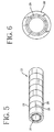
- the delivery system shown in Figures 5 and 6 comprises a prosthesis 20, said prosthesis being radially expandable under a first radially expansive force and a second radially expansive force.
- a balloon catheter 2 as shown in Figure 1 may be expanded to supply said second radially expansive force, said second radially expansive force being greater than said first expansive force of said prosthesis.
- Catheter sheath 22 of Figures 5 and 6 possesses a yield strength which is greater than the first expansive force of said prosthesis, and less than said second expansive force of the balloon catheter.
- delivery sheath 22 of Figure 5 allows implantation of the prosthesis, as the yield strength of delivery sheath 22 is less than the second expansive force.
- the application of the second expansive force therefore effectively deploys the prosthesis, as it surpasses the yield strength of the sheath, and the prosthesis is expanded to its active radius.
- the yield strength of sheath 22 is provided by its configuration, particularly the area where ends 26 and 28 of the polymeric strips meet.
- the seam where the strips meet each other may provide an area of decreased strength, depending on how the ends are adhered to each other, or to the prosthesis. These weak points provide "break-away" points which allow deployment of the prosthesis without movement of the exterior sheath.
- an area of decreased tensile strength can be constructed into a delivery sheath in a number of ways.
- notches can be engineered into any of the sheaths disclosed in the present invention.
- the term notches, as used herein, means an area of decreased tensile strength in a sheath.
- Notches are typically longitudinally extending slits in the delivery sheath.
- a delivery sheath includes a plurality of longitudinally aligned slits.
- a notch can be engineered into a sheath in a number of different ways, including simply cutting away a section of a sheath.
- Notches can be further lined up along a longitudinal axis of a delivery sheath to provide a line of decreased resistance in the delivery sheath. Such a line provides a line in the sheath for a controlled expansion of the sheath similar to a line of perforation.
- a notch can be anywhere from 1 to 400 millimeters long, preferably in the range of 5 to 10 millimeters.
- Notches can be on either a luminal or exterior surface of a tubular sheath.
- the aligned notches can be in the range of 1 to 400 millimeters long.
- Figure 6 shows a cross-section of such a delivery system after an expansive deformation has taken place.
- the polymeric strips comprising delivery sheath may be formed of PTFE, ePTFE, FEP, PEEK, PI, nylon, polyurethane, PE, PBT, and other thermoplastic elastomers, not mentioned.
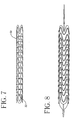
- Figure 7 shows a perspective of the delivery system of the present invention wherein the delivery sheath is comprised of polymeric strips 30, and said polymeric strips are comprised of a thin suture.
- Polymeric strips comprising the delivery sheath may be formed of such a suture, but also may be formed of a yam, ribbon, or thread.
- Polymeric strips, 30 may have a predetermined section of decreased tensile strength 32, which upon expansion of the prosthesis, yields to allow implantation of the prosthesis.
- Figure 8 is a perspective showing an expanded prosthesis with polymeric strips allowing implantation in such a manner.
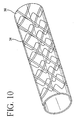
- Figure 9 shows a perspective of the delivery system of the present invention wherein the delivery sheath is comprised of polymeric strips 34 wound helically in a continuous band around, through, or within stent/graft prosthesis 36.
- the continuous winding is shown with a tape-like polymeric winding, but other forms are contemplated within the present invention.
- the continuous helical winding may be with a thin suture, yarn, ribbon, or thread.
- the predetermined yield strength of the delivery sheath may be achieved as a result of the material used, the thinness of the material, or with a predetermined section of decreased tensile strength which may be manufactured into the sheath.
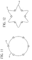
- a prosthesis, stent 38 is shown in cross-section in Figure 11 in its expanded state a with a tubular cover 40.
- Tubular cover 40 is integrally associated with stent 38.
- Tubular structure 40 is placed circumferentially on the exterior surface of stent 38 in its expanded state, where it is held taught by the expanded stent.
- Tubular cover 40 may also be placed circumferentially on the interior of stent 38, or on both sides.
- the stent may be on a mandrel.
- the stent is then collapsed, and reduced in diameter to its compressed condition as shown in Figure 12. This leaves areas of slack 42 in tubular cover 40 as seen in the cross-section in Figure 12.
- tubular cover 40 The selected portions of slack 42 of tubular cover 40 are then wrapped around stent 38 folded over itself as seen in the cross-section shown in Figure 13. Tubular cover 40 is then adhered to itself at selected areas 44 of the cover.
- the adhesion may take place by any means discussed above, including adhesively adhering, sintering, thermal adhesion, or adhesion by other mechanical means.
- the tubular cover may be comprised of a number of polymeric materials, including but not limited to a polymer selected from the group consisting of PTFE, ePTFE, nylon, polyurethane, polyimide, polyether ether ketone. fluorinated ethylene propylene, and polybutylene terephthalate.
- tubular cover 40 is integrally associated with the prosthesis, and a reduced profile is created for the delivery system. which provides for easier, and more efficient delivery of the prosthesis.
- the selected areas of adhesion 44 provide for an area of decreased tensile strength with respect to the tubular cover.
- a balloon catheter is inserted within the stent 38, and expansion of the balloon catheter ruptures the tubular cover 40 at areas of adhesion 44.
- tubular cover 40 is bio-compatible or biodegradable and may be assimilated within the body, and remains implanted with stent 38.
- a sheath may be comprised of bio-absorbable materials.
- bio-absorbable as used in this disclosure is synonymous with biodegradable, meaning the ability to be degraded by processes involving biological conditions, such as those present in the bodies of humans or other animals. More specifically, this term indicates the physical or chemical breaking down of the polymer into smaller units which are preferably innocuous, non-toxic and are readily eliminated or metabolized by the body.
- bio-absorbable materials which may be used include polymers, copolymers, block polymers, and mixtures thereof.
- Bio-absorbable polymers and polymer classes include, but are not limited to the following: poly(glycolic acid) (PGA), poly(lactic acid) (PLA); polydioxanes, polyoxalates, poly( ⁇ -esters), polyanhydrides, polyacetates, polycaprolactones, poly(orthoesters), polyamino acids, polyurethanes, polycarbonates, polyiminocarbonates, polyamides, poly(alkyl cyanoacrylates), and mixtures and copolymers thereof.
- PGA poly(glycolic acid)
- PLA poly(lactic acid)
- polyanhydrides polyacetates
- polycaprolactones poly(orthoesters)
- polyamino acids polyurethanes
- polycarbonates polyiminocarbonates
- polyamides poly(alkyl cyanoacrylates
- Additional useful polymers include, stereopolymers of L- and D-lactic acid, copolymers of bis(p-carboxyphenoxy) proprionic acid and sebacic acid, sebacic acid copolymers, copolymers of caprolactone, poly(lactic acid)/poly(glycoclic acid)/polyethyleneglycol copolymers, copolymers of polyurethane and poly(lactic acid), copolymers of ⁇ -amino acids, copolymers of ⁇ -amino acids and caproic acid, copolymers of ⁇ -benzyl glutamate and polyethylene glycol, copolymers of succinate and poly(glycols), polyphosphazene, polyhydroxy-alkanoates and mixtures thereof. Binary and ternary systems are contemplated.
Landscapes
- Health & Medical Sciences (AREA)
- Engineering & Computer Science (AREA)
- Biomedical Technology (AREA)
- Cardiology (AREA)
- Oral & Maxillofacial Surgery (AREA)
- Transplantation (AREA)
- Heart & Thoracic Surgery (AREA)
- Vascular Medicine (AREA)
- Life Sciences & Earth Sciences (AREA)
- Animal Behavior & Ethology (AREA)
- General Health & Medical Sciences (AREA)
- Public Health (AREA)
- Veterinary Medicine (AREA)
- Gastroenterology & Hepatology (AREA)
- Pulmonology (AREA)
- Materials For Medical Uses (AREA)
- Prostheses (AREA)
- Media Introduction/Drainage Providing Device (AREA)
Abstract
Claims (7)
- Un système de pose de prothèse endoluminale comprenant une prothèse endoluminale tubulaire (4, 20) ayant une surface luminale et une surface extérieure opposée, où ladite prothèse est radialement expansible entre une position compressée par une première force expansive radiale et par une deuxième force expansive radiale qui est plus grande que ladite première force expansive ; et une gaine de pose (6, 14, 17, 22) maintenant ladite prothèse dans ladite condition compressée, où ladite gaine de pose possède une limite élastique qui est plus grande que ladite première force expansive de ladite prothèse, et plus petite que ladite seconde force expansive, caractérisé en ce que ladite gaine de pose comprend une pluralité de segments (16, 19), formés à partir d'une première matière polymérique, qui sont intégrés de façon intermittente dans un corps tubulaire (18, 21) d'une seconde matière polymérique.
- Un système de pose de prothèse endoluminale selon la revendication 1, caractérisé en ce que le corps tubulaire (18) a un axe d'extension longitudinal et la première matière polymérique comprend des segments d'extension longitudinaux (16) intégrés dans ledit corps de la seconde matière polymérique et s'étirant parallèlement au dit axe longitudinal.
- Un système de pose de prothèse endoluminale selon la revendication 1, caractérisé en ce que ledit corps tubulaire (21) a une circonférence et un axe longitudinal, où ladite première matière polymérique comprend des segments circonférentiels (19) qui sont intégrés de façon intermittente dans ladite seconde matière polymérique et disposés transversalement au dit axe longitudinal.
- Un système de pose de prothèse endoluminale selon l'une quelconque des revendications précédentes, caractérisé en ce que ladite première matière polymérique possède une première résistance à la traction et ladite seconde matière polymérique possède une seconde résistance à la traction plus grande que ladite première résistance à la traction.
- Un système de pose de prothèse endoluminale selon l'une quelconque des revendications précédentes, caractérisé en ce que ladite première matière polymérique possède une première résistance à la traction et ladite seconde matière polymérique possède une seconde résistance à la traction plus petite que ladite première résistance à la traction.
- Un système de pose de prothèse endoluminale selon l'une quelconque des revendications précédentes, caractérisé en ce que ladite gaine de pose (6, 14, 17, 22) est une couverture tubulaire intégralement associée avec ladite prothèse (4, 20), où ladite couverture tubulaire adhère à elle-même en des zones sélectionnées avec une force à la traction diminuée.
- Un système de pose de prothèse endoluminale selon l'une quelconque des revendications précédentes, caractérisé en ce que ladite gaine de pose inclut en plus des fentes longitudinalement alignées.
Applications Claiming Priority (3)
| Application Number | Priority Date | Filing Date | Title |
|---|---|---|---|
| US09/409,620 US6533806B1 (en) | 1999-10-01 | 1999-10-01 | Balloon yielded delivery system and endovascular graft design for easy deployment |
| US409620 | 1999-10-01 | ||
| PCT/US2000/025720 WO2001024733A1 (fr) | 1999-10-01 | 2000-09-20 | Dispositif d'administration a fluage par ballonnet et modele de greffe endovasculaire permettant le deploiement facile |
Publications (2)
| Publication Number | Publication Date |
|---|---|
| EP1237502A1 EP1237502A1 (fr) | 2002-09-11 |
| EP1237502B1 true EP1237502B1 (fr) | 2005-04-06 |
Family
ID=23621285
Family Applications (1)
| Application Number | Title | Priority Date | Filing Date |
|---|---|---|---|
| EP00963638A Expired - Lifetime EP1237502B1 (fr) | 1999-10-01 | 2000-09-20 | Dispositif d'administration a fluage par ballonnet et modele de greffe endovasculaire permettant le deploiement facile |
Country Status (6)
| Country | Link |
|---|---|
| US (2) | US6533806B1 (fr) |
| EP (1) | EP1237502B1 (fr) |
| AU (1) | AU4026601A (fr) |
| CA (1) | CA2383501C (fr) |
| DE (1) | DE60019332T2 (fr) |
| WO (1) | WO2001024733A1 (fr) |
Families Citing this family (106)
| Publication number | Priority date | Publication date | Assignee | Title |
|---|---|---|---|---|
| DK63894A (da) * | 1994-06-06 | 1996-01-08 | Meadox Medicals Inc | Kateter med stent samt fremgangsmåde til fremstilling af et sådant kateter med stent |
| US6312458B1 (en) * | 2000-01-19 | 2001-11-06 | Scimed Life Systems, Inc. | Tubular structure/stent/stent securement member |
| US6602280B2 (en) * | 2000-02-02 | 2003-08-05 | Trivascular, Inc. | Delivery system and method for expandable intracorporeal device |
| US20030050684A1 (en) * | 2001-09-10 | 2003-03-13 | Abrams Robert M. | Internal restraint for delivery of self-expanding stents |
| US6899727B2 (en) | 2001-01-22 | 2005-05-31 | Gore Enterprise Holdings, Inc. | Deployment system for intraluminal devices |
| US6733521B2 (en) | 2001-04-11 | 2004-05-11 | Trivascular, Inc. | Delivery system and method for endovascular graft |
| US6761733B2 (en) | 2001-04-11 | 2004-07-13 | Trivascular, Inc. | Delivery system and method for bifurcated endovascular graft |
| US20040138734A1 (en) * | 2001-04-11 | 2004-07-15 | Trivascular, Inc. | Delivery system and method for bifurcated graft |
| US6951570B2 (en) * | 2001-07-02 | 2005-10-04 | Rubicon Medical, Inc. | Methods, systems, and devices for deploying a filter from a filter device |
| US20100016943A1 (en) | 2001-12-20 | 2010-01-21 | Trivascular2, Inc. | Method of delivering advanced endovascular graft |
| US6946173B2 (en) * | 2002-03-21 | 2005-09-20 | Advanced Cardiovascular Systems, Inc. | Catheter balloon formed of ePTFE and a diene polymer |
| US20030181810A1 (en) * | 2002-03-25 | 2003-09-25 | Murphy Kieran P. | Kit for image guided surgical procedures |
| US9375203B2 (en) | 2002-03-25 | 2016-06-28 | Kieran Murphy Llc | Biopsy needle |
| US7927368B2 (en) | 2002-03-25 | 2011-04-19 | Kieran Murphy Llc | Device viewable under an imaging beam |
| US20030204248A1 (en) * | 2002-03-25 | 2003-10-30 | Murphy Kieran P. | Device viewable under an imaging beam |
| US7198636B2 (en) * | 2003-01-17 | 2007-04-03 | Gore Enterprise Holdings, Inc. | Deployment system for an endoluminal device |
| US20060058866A1 (en) * | 2003-01-17 | 2006-03-16 | Cully Edward H | Deployment system for an expandable device |
| AU2007237298B2 (en) * | 2003-01-17 | 2010-07-01 | W. L. Gore & Associates, Inc. | Deployment system for an endoluminal device |
| US7753945B2 (en) * | 2003-01-17 | 2010-07-13 | Gore Enterprise Holdings, Inc. | Deployment system for an endoluminal device |
| US20050049672A1 (en) * | 2003-03-24 | 2005-03-03 | Murphy Kieran P. | Stent delivery system and method using a balloon for a self-expandable stent |
| US7060038B2 (en) * | 2003-04-24 | 2006-06-13 | Medtronic Vascular, Inc. | Device for delivering a sensor to the endovascular system and method of use |
| US8318078B2 (en) * | 2003-06-23 | 2012-11-27 | Boston Scientific Scimed, Inc. | Asymmetric stent delivery system with proximal edge protection and method of manufacture thereof |
| US9198786B2 (en) | 2003-09-03 | 2015-12-01 | Bolton Medical, Inc. | Lumen repair device with capture structure |
| US11259945B2 (en) | 2003-09-03 | 2022-03-01 | Bolton Medical, Inc. | Dual capture device for stent graft delivery system and method for capturing a stent graft |
| US20080264102A1 (en) | 2004-02-23 | 2008-10-30 | Bolton Medical, Inc. | Sheath Capture Device for Stent Graft Delivery System and Method for Operating Same |
| US20070198078A1 (en) | 2003-09-03 | 2007-08-23 | Bolton Medical, Inc. | Delivery system and method for self-centering a Proximal end of a stent graft |
| US8500792B2 (en) | 2003-09-03 | 2013-08-06 | Bolton Medical, Inc. | Dual capture device for stent graft delivery system and method for capturing a stent graft |
| US7763063B2 (en) | 2003-09-03 | 2010-07-27 | Bolton Medical, Inc. | Self-aligning stent graft delivery system, kit, and method |
| US8292943B2 (en) | 2003-09-03 | 2012-10-23 | Bolton Medical, Inc. | Stent graft with longitudinal support member |
| US11596537B2 (en) | 2003-09-03 | 2023-03-07 | Bolton Medical, Inc. | Delivery system and method for self-centering a proximal end of a stent graft |
| US8157855B2 (en) * | 2003-12-05 | 2012-04-17 | Boston Scientific Scimed, Inc. | Detachable segment stent |
| US20050278011A1 (en) * | 2004-06-10 | 2005-12-15 | Peckham John E | Stent delivery system |
| US8308789B2 (en) * | 2004-07-16 | 2012-11-13 | W. L. Gore & Associates, Inc. | Deployment system for intraluminal devices |
| US7765670B2 (en) * | 2004-08-13 | 2010-08-03 | Boston Scientific Scimed, Inc. | Method to simultaneously load and cover self expanding stents |
| US7691137B2 (en) * | 2004-09-28 | 2010-04-06 | Boston Scientific Scimed, Inc. | Rotatable sheath, assembly and method of manufacture of same |
| US20060074478A1 (en) * | 2004-09-28 | 2006-04-06 | Feller Frederick Iii | Thin film medical device and delivery system |
| ATE458458T1 (de) * | 2006-03-24 | 2010-03-15 | Cordis Corp | Splitschleusenfreisetzungssystem für selbstexpandierende stents |
| EP2049050A1 (fr) * | 2006-08-08 | 2009-04-22 | Medlogics Device Corporation | Dispositifs, systemes & procedes d'acheminement de stent |
| US8066755B2 (en) | 2007-09-26 | 2011-11-29 | Trivascular, Inc. | System and method of pivoted stent deployment |
| US8663309B2 (en) | 2007-09-26 | 2014-03-04 | Trivascular, Inc. | Asymmetric stent apparatus and method |
| US8226701B2 (en) | 2007-09-26 | 2012-07-24 | Trivascular, Inc. | Stent and delivery system for deployment thereof |
| AU2008308474B2 (en) | 2007-10-04 | 2014-07-24 | Trivascular, Inc. | Modular vascular graft for low profile percutaneous delivery |
| US8083789B2 (en) | 2007-11-16 | 2011-12-27 | Trivascular, Inc. | Securement assembly and method for expandable endovascular device |
| US8328861B2 (en) | 2007-11-16 | 2012-12-11 | Trivascular, Inc. | Delivery system and method for bifurcated graft |
| DE102008021066A1 (de) * | 2008-04-26 | 2009-10-29 | Biotronik Vi Patent Ag | Stentbefestigungssystem |
| JP5484458B2 (ja) | 2008-06-30 | 2014-05-07 | ボルトン メディカル インコーポレイテッド | 腹部大動脈瘤システム |
| AU2010223953B2 (en) * | 2009-03-13 | 2014-05-01 | Bolton Medical, Inc. | System and method for deploying an endoluminal prosthesis at a surgical site |
| US8870950B2 (en) | 2009-12-08 | 2014-10-28 | Mitral Tech Ltd. | Rotation-based anchoring of an implant |
| US20110224785A1 (en) | 2010-03-10 | 2011-09-15 | Hacohen Gil | Prosthetic mitral valve with tissue anchors |
| US9763657B2 (en) | 2010-07-21 | 2017-09-19 | Mitraltech Ltd. | Techniques for percutaneous mitral valve replacement and sealing |
| US11653910B2 (en) | 2010-07-21 | 2023-05-23 | Cardiovalve Ltd. | Helical anchor implantation |
| US10111767B2 (en) | 2010-10-29 | 2018-10-30 | Abbott Cardiovascular Systems Inc. | Sheaths used in polymer scaffold delivery systems |
| US10617514B2 (en) | 2010-12-22 | 2020-04-14 | W. L. Gore & Associates, Inc. | Biased endoluminal device |
| US10166128B2 (en) | 2011-01-14 | 2019-01-01 | W. L. Gore & Associates. Inc. | Lattice |
| US8414528B2 (en) | 2011-05-27 | 2013-04-09 | Abbott Cardiovascular Systems Inc. | Polymer scaffold sheaths |
| US8852257B2 (en) | 2011-06-21 | 2014-10-07 | Abbott Cardiovascular Systems Inc. | Sheaths used with polymer scaffold |
| US8852272B2 (en) | 2011-08-05 | 2014-10-07 | Mitraltech Ltd. | Techniques for percutaneous mitral valve replacement and sealing |
| WO2013021374A2 (fr) | 2011-08-05 | 2013-02-14 | Mitraltech Ltd. | Techniques pour le remplacement et la fixation percutanés d'une valvule mitrale |
| US20140324164A1 (en) * | 2011-08-05 | 2014-10-30 | Mitraltech Ltd. | Techniques for percutaneous mitral valve replacement and sealing |
| EP3417813B1 (fr) | 2011-08-05 | 2020-05-13 | Cardiovalve Ltd | Remplacement percutané d'une valvule mitrale |
| US10213329B2 (en) | 2011-08-12 | 2019-02-26 | W. L. Gore & Associates, Inc. | Evertable sheath devices, systems, and methods |
| US8992595B2 (en) | 2012-04-04 | 2015-03-31 | Trivascular, Inc. | Durable stent graft with tapered struts and stable delivery methods and devices |
| US9498363B2 (en) | 2012-04-06 | 2016-11-22 | Trivascular, Inc. | Delivery catheter for endovascular device |
| BR112014025430A2 (pt) | 2012-04-12 | 2020-03-10 | Bolton Medical, Inc. | Dispositivo de envio protético vascular e método de uso |
| JP2014090969A (ja) * | 2012-11-06 | 2014-05-19 | Kyoto Medical Planning Ltd | ステント供給装置 |
| US8628571B1 (en) | 2012-11-13 | 2014-01-14 | Mitraltech Ltd. | Percutaneously-deliverable mechanical valve |
| US9072590B2 (en) | 2012-12-07 | 2015-07-07 | Abbott Cardiovascular Systems Inc. | Sheaths reducing recoil and loss of retention for polymer scaffolds crimped to balloons |
| US9907641B2 (en) | 2014-01-10 | 2018-03-06 | W. L. Gore & Associates, Inc. | Implantable intraluminal device |
| EP2948103B1 (fr) | 2013-01-24 | 2022-12-07 | Cardiovalve Ltd | Valves prothétiques à ancrage ventriculaire |
| US9763819B1 (en) | 2013-03-05 | 2017-09-19 | W. L. Gore & Associates, Inc. | Tapered sleeve |
| US9439751B2 (en) | 2013-03-15 | 2016-09-13 | Bolton Medical, Inc. | Hemostasis valve and delivery systems |
| EP2991718B1 (fr) | 2013-05-03 | 2019-11-13 | C.R. Bard, Inc. | Gaine protectrice pouvant être pelée |
| US9675483B2 (en) | 2013-06-21 | 2017-06-13 | Abbott Cardiovascular Systems Inc. | Protective sheath assembly for a polymer scaffold |
| US9788983B2 (en) | 2013-06-21 | 2017-10-17 | Abbott Cardiovascular Systems Inc. | Removable sheath assembly for a polymer scaffold |
| US10098771B2 (en) | 2013-09-25 | 2018-10-16 | Abbott Cardiovascular Systems Inc. | Clip sheath for a polymer scaffold |
| US9913958B2 (en) | 2014-02-28 | 2018-03-13 | Abbott Cardiovascular Systems Inc. | Protective sheaths for medical devices |
| US10966850B2 (en) | 2014-03-06 | 2021-04-06 | W. L. Gore & Associates, Inc. | Implantable medical device constraint and deployment apparatus |
| US9364361B2 (en) | 2014-03-13 | 2016-06-14 | Abbott Cardiovascular Systems Inc. | Striped sheaths for medical devices |
| EP3174502B1 (fr) | 2014-07-30 | 2022-04-06 | Cardiovalve Ltd | Appareil d'implantation de prothèse valvulaire articulable |
| EP3253333B1 (fr) | 2015-02-05 | 2024-04-03 | Cardiovalve Ltd | Valve prothétique avec cadres coulissant axialement |
| US9974651B2 (en) | 2015-02-05 | 2018-05-22 | Mitral Tech Ltd. | Prosthetic valve with axially-sliding frames |
| EP4327787A3 (fr) | 2015-05-27 | 2024-05-08 | TriVascular, Inc. | Déploiement de prothèse endoluminale assisté par ballonnet |
| US10531866B2 (en) | 2016-02-16 | 2020-01-14 | Cardiovalve Ltd. | Techniques for providing a replacement valve and transseptal communication |
| JP7248430B2 (ja) | 2016-04-21 | 2023-03-29 | ダブリュ.エル.ゴア アンド アソシエイツ,インコーポレイティド | 直径を調節可能な内部人工器官ならびに関連したシステムおよび方法 |
| US20190231525A1 (en) | 2016-08-01 | 2019-08-01 | Mitraltech Ltd. | Minimally-invasive delivery systems |
| CN109789018B (zh) | 2016-08-10 | 2022-04-26 | 卡迪尔维尔福股份有限公司 | 具有同轴框架的人工瓣膜 |
| USD800908S1 (en) | 2016-08-10 | 2017-10-24 | Mitraltech Ltd. | Prosthetic valve element |
| CN108295359B (zh) * | 2016-12-30 | 2021-05-07 | 先健科技(深圳)有限公司 | 载药器械及其制备方法 |
| EP3576672B1 (fr) | 2017-01-31 | 2026-05-06 | W. L. Gore & Associates, Inc. | Éléments de stent pré-contraints |
| US10888421B2 (en) | 2017-09-19 | 2021-01-12 | Cardiovalve Ltd. | Prosthetic heart valve with pouch |
| US11793633B2 (en) | 2017-08-03 | 2023-10-24 | Cardiovalve Ltd. | Prosthetic heart valve |
| US12064347B2 (en) | 2017-08-03 | 2024-08-20 | Cardiovalve Ltd. | Prosthetic heart valve |
| US10575948B2 (en) | 2017-08-03 | 2020-03-03 | Cardiovalve Ltd. | Prosthetic heart valve |
| US10537426B2 (en) | 2017-08-03 | 2020-01-21 | Cardiovalve Ltd. | Prosthetic heart valve |
| US11246704B2 (en) | 2017-08-03 | 2022-02-15 | Cardiovalve Ltd. | Prosthetic heart valve |
| US12458493B2 (en) | 2017-09-19 | 2025-11-04 | Cardiovalve Ltd. | Prosthetic heart valve and delivery systems and methods |
| ES2960532T3 (es) | 2017-10-11 | 2024-03-05 | Gore & Ass | Aparato de restricción y despliegue de dispositivos médicos implantables |
| GB201720803D0 (en) | 2017-12-13 | 2018-01-24 | Mitraltech Ltd | Prosthetic Valve and delivery tool therefor |
| GB201800399D0 (en) | 2018-01-10 | 2018-02-21 | Mitraltech Ltd | Temperature-control during crimping of an implant |
| WO2019159062A1 (fr) | 2018-02-13 | 2019-08-22 | Murphy Kieran P | Système d'administration pour administrer une forme retard à un site cible sous guidage d'image, et méthodes et utilisations de celui-ci |
| US11389627B1 (en) | 2018-10-02 | 2022-07-19 | Lutonix Inc. | Balloon protectors, balloon-catheter assemblies, and methods thereof |
| US12521225B2 (en) | 2019-01-31 | 2026-01-13 | Becton, Dickinson And Company | Mixed-frame intraluminal prosthesis and methods thereof |
| US11752020B2 (en) * | 2019-06-19 | 2023-09-12 | Michael J. Spearman | Tool for placement of degradable ostial stent |
| EP4171449B1 (fr) | 2020-06-24 | 2026-03-04 | Bolton Medical, Inc. | Composant anti-retour pour dispositif de pose de prothèse vasculaire |
| WO2022079708A1 (fr) * | 2020-10-14 | 2022-04-21 | Stomtop Ltd. | Dispositifs de stomie |
| US12357459B2 (en) | 2020-12-03 | 2025-07-15 | Cardiovalve Ltd. | Transluminal delivery system |
Family Cites Families (53)
| Publication number | Priority date | Publication date | Assignee | Title |
|---|---|---|---|---|
| US2810424A (en) * | 1953-03-20 | 1957-10-22 | Aetna Standard Eng Co | Method and apparatus for making reinforced plastic tubing |
| US3508297A (en) * | 1968-01-10 | 1970-04-28 | Ind Des Silicones Soc | Apparatus for continuous production of reinforced conduit |
| US3962153A (en) | 1970-05-21 | 1976-06-08 | W. L. Gore & Associates, Inc. | Very highly stretched polytetrafluoroethylene and process therefor |
| CA962021A (en) | 1970-05-21 | 1975-02-04 | Robert W. Gore | Porous products and process therefor |
| US3905853A (en) * | 1970-05-21 | 1975-09-16 | Creators Ltd | Reinforced plastics tubes |
| US5693083A (en) | 1983-12-09 | 1997-12-02 | Endovascular Technologies, Inc. | Thoracic graft and delivery catheter |
| US5104399A (en) | 1986-12-10 | 1992-04-14 | Endovascular Technologies, Inc. | Artificial graft and implantation method |
| US4738666A (en) * | 1985-06-11 | 1988-04-19 | Genus Catheter Technologies, Inc. | Variable diameter catheter |
| WO1990001969A1 (fr) | 1988-08-24 | 1990-03-08 | Slepian Marvin J | Etancheification a l'aide d'un polymere biodegradable de la surface interieure d'une lumiere d'un organe |
| US5234425A (en) | 1989-03-03 | 1993-08-10 | Thomas J. Fogarty | Variable diameter sheath method and apparatus for use in body passages |
| JP2545981B2 (ja) * | 1989-05-09 | 1996-10-23 | 東レ株式会社 | バルーン付カテーテル |
| US5116318A (en) | 1989-06-06 | 1992-05-26 | Cordis Corporation | Dilatation balloon within an elastic sleeve |
| US5078720A (en) | 1990-05-02 | 1992-01-07 | American Medical Systems, Inc. | Stent placement instrument and method |
| US5199951A (en) | 1990-05-17 | 1993-04-06 | Wayne State University | Method of drug application in a transporting medium to an arterial wall injured during angioplasty |
| US5360443A (en) | 1990-06-11 | 1994-11-01 | Barone Hector D | Aortic graft for repairing an abdominal aortic aneurysm |
| US5190058A (en) | 1991-05-22 | 1993-03-02 | Medtronic, Inc. | Method of using a temporary stent catheter |
| US5372600A (en) | 1991-10-31 | 1994-12-13 | Instent Inc. | Stent delivery systems |
| US5316023A (en) | 1992-01-08 | 1994-05-31 | Expandable Grafts Partnership | Method for bilateral intra-aortic bypass |
| DE59208138D1 (de) | 1992-10-12 | 1997-04-10 | Schneider Europ Ag | Katheter mit einer Gefässstütze |
| US5409495A (en) | 1993-08-24 | 1995-04-25 | Advanced Cardiovascular Systems, Inc. | Apparatus for uniformly implanting a stent |
| US5571135A (en) | 1993-10-22 | 1996-11-05 | Scimed Life Systems Inc. | Stent delivery apparatus and method |
| US5562617A (en) | 1994-01-18 | 1996-10-08 | Finch, Jr.; Charles D. | Implantable vascular device |
| US5403341A (en) * | 1994-01-24 | 1995-04-04 | Solar; Ronald J. | Parallel flow endovascular stent and deployment apparatus therefore |
| US5453090A (en) | 1994-03-01 | 1995-09-26 | Cordis Corporation | Method of stent delivery through an elongate softenable sheath |
| US5665114A (en) * | 1994-08-12 | 1997-09-09 | Meadox Medicals, Inc. | Tubular expanded polytetrafluoroethylene implantable prostheses |
| US5639276A (en) | 1994-09-23 | 1997-06-17 | Rapid Development Systems, Inc. | Device for use in right ventricular placement and method for using same |
| US5637113A (en) * | 1994-12-13 | 1997-06-10 | Advanced Cardiovascular Systems, Inc. | Polymer film for wrapping a stent structure |
| AU719980B2 (en) * | 1995-02-22 | 2000-05-18 | Menlo Care, Inc. | Covered expanding mesh stent |
| US6264684B1 (en) | 1995-03-10 | 2001-07-24 | Impra, Inc., A Subsidiary Of C.R. Bard, Inc. | Helically supported graft |
| US5647857A (en) | 1995-03-16 | 1997-07-15 | Endotex Interventional Systems, Inc. | Protective intraluminal sheath |
| US5807398A (en) | 1995-04-28 | 1998-09-15 | Shaknovich; Alexander | Shuttle stent delivery catheter |
| US5702373A (en) * | 1995-08-31 | 1997-12-30 | Target Therapeutics, Inc. | Composite super-elastic alloy braid reinforced catheter |
| US5534007A (en) | 1995-05-18 | 1996-07-09 | Scimed Life Systems, Inc. | Stent deployment catheter with collapsible sheath |
| US5591195A (en) * | 1995-10-30 | 1997-01-07 | Taheri; Syde | Apparatus and method for engrafting a blood vessel |
| FR2742994B1 (fr) | 1995-12-28 | 1998-04-03 | Sgro Jean-Claude | Ensemble de traitement chirurgical d'une lumiere intracorporelle |
| US5843158A (en) | 1996-01-05 | 1998-12-01 | Medtronic, Inc. | Limited expansion endoluminal prostheses and methods for their use |
| US5690643A (en) | 1996-02-20 | 1997-11-25 | Leocor, Incorporated | Stent delivery system |
| US5630830A (en) | 1996-04-10 | 1997-05-20 | Medtronic, Inc. | Device and method for mounting stents on delivery systems |
| US5669932A (en) | 1996-05-29 | 1997-09-23 | Isostent, Inc. | Means for accurately positioning an expandable stent |
| US5709701A (en) | 1996-05-30 | 1998-01-20 | Parodi; Juan C. | Apparatus for implanting a prothesis within a body passageway |
| US5843161A (en) | 1996-06-26 | 1998-12-01 | Cordis Corporation | Endoprosthesis assembly for percutaneous deployment and method of deploying same |
| US5980530A (en) * | 1996-08-23 | 1999-11-09 | Scimed Life Systems Inc | Stent delivery system |
| US6254628B1 (en) * | 1996-12-09 | 2001-07-03 | Micro Therapeutics, Inc. | Intracranial stent |
| US5824046A (en) * | 1996-09-27 | 1998-10-20 | Scimed Life Systems, Inc. | Covered stent |
| US6086610A (en) * | 1996-10-22 | 2000-07-11 | Nitinol Devices & Components | Composite self expanding stent device having a restraining element |
| EP1014887B1 (fr) | 1996-12-10 | 2006-04-19 | Purdue Research Foundation | Stent a trombogenicite reduite |
| US5792144A (en) | 1997-03-31 | 1998-08-11 | Cathco, Inc. | Stent delivery catheter system |
| US6015432A (en) * | 1998-02-25 | 2000-01-18 | Cordis Corporation | Wire reinforced vascular prosthesis |
| US6520983B1 (en) * | 1998-03-31 | 2003-02-18 | Scimed Life Systems, Inc. | Stent delivery system |
| US6306163B1 (en) * | 1998-08-04 | 2001-10-23 | Advanced Cardiovascular Systems, Inc. | Assembly for collecting emboli and method of use |
| US6350277B1 (en) | 1999-01-15 | 2002-02-26 | Scimed Life Systems, Inc. | Stents with temporary retaining bands |
| US6331186B1 (en) * | 1999-03-22 | 2001-12-18 | Scimed Life Systems, Inc. | End sleeve coating for stent delivery |
| US6432130B1 (en) | 2000-04-20 | 2002-08-13 | Scimed Life Systems, Inc. | Fully sheathed balloon expandable stent delivery system |
-
1999
- 1999-10-01 US US09/409,620 patent/US6533806B1/en not_active Expired - Lifetime
-
2000
- 2000-09-20 AU AU40266/01A patent/AU4026601A/en not_active Abandoned
- 2000-09-20 CA CA002383501A patent/CA2383501C/fr not_active Expired - Fee Related
- 2000-09-20 DE DE60019332T patent/DE60019332T2/de not_active Expired - Lifetime
- 2000-09-20 WO PCT/US2000/025720 patent/WO2001024733A1/fr not_active Ceased
- 2000-09-20 EP EP00963638A patent/EP1237502B1/fr not_active Expired - Lifetime
-
2002
- 2002-09-23 US US10/253,558 patent/US8048138B2/en not_active Expired - Fee Related
Also Published As
| Publication number | Publication date |
|---|---|
| EP1237502A1 (fr) | 2002-09-11 |
| CA2383501C (fr) | 2009-05-26 |
| AU4026601A (en) | 2001-05-10 |
| US20030028237A1 (en) | 2003-02-06 |
| WO2001024733A1 (fr) | 2001-04-12 |
| DE60019332T2 (de) | 2006-03-09 |
| US6533806B1 (en) | 2003-03-18 |
| US8048138B2 (en) | 2011-11-01 |
| CA2383501A1 (fr) | 2001-04-12 |
| DE60019332D1 (de) | 2005-05-12 |
Similar Documents
| Publication | Publication Date | Title |
|---|---|---|
| EP1237502B1 (fr) | Dispositif d'administration a fluage par ballonnet et modele de greffe endovasculaire permettant le deploiement facile | |
| EP1251798B1 (fr) | Extenseur-endoprothese comportant un element de fixation helicoidal | |
| EP2059198B1 (fr) | Stents avec raccords et éléments de stabilisation biodégradables | |
| EP2282705B1 (fr) | Dispositif médical déployable contrôlé et procédé de fabrication de celui-ci | |
| US5779732A (en) | Method and apparatus for implanting a film with an exandable stent | |
| JP4584832B2 (ja) | ステント供給装置 | |
| US20040044395A1 (en) | Elephant trunk thoracic endograft and delivery system | |
| JP2005510260A (ja) | 制御膨張式ステント | |
| JP2005533557A (ja) | 管腔内拡張システム | |
| EP1420721A1 (fr) | Extenseur hybride pouvant se dilater sous l'effet d'un ballonnet ou automatiquement | |
| US7556643B2 (en) | Graft inside stent | |
| WO1996027347A1 (fr) | Greffe intraluminale composite | |
| EP0836449A1 (fr) | Greffe prosthetique et procede de reparation d'un anevrisme | |
| JP2025019210A (ja) | デバイス展開機能を備えたデリバリーシステム及び関連方法 |
Legal Events
| Date | Code | Title | Description |
|---|---|---|---|
| PUAI | Public reference made under article 153(3) epc to a published international application that has entered the european phase |
Free format text: ORIGINAL CODE: 0009012 |
|
| 17P | Request for examination filed |
Effective date: 20020502 |
|
| AK | Designated contracting states |
Kind code of ref document: A1 Designated state(s): AT BE CH CY DE DK ES FI FR GB GR IE IT LI LU MC NL PT SE |
|
| AX | Request for extension of the european patent |
Free format text: AL;LT;LV;MK;RO;SI |
|
| 17Q | First examination report despatched |
Effective date: 20040305 |
|
| RBV | Designated contracting states (corrected) |
Designated state(s): DE FR GB IE IT |
|
| GRAP | Despatch of communication of intention to grant a patent |
Free format text: ORIGINAL CODE: EPIDOSNIGR1 |
|
| GRAS | Grant fee paid |
Free format text: ORIGINAL CODE: EPIDOSNIGR3 |
|
| GRAA | (expected) grant |
Free format text: ORIGINAL CODE: 0009210 |
|
| AK | Designated contracting states |
Kind code of ref document: B1 Designated state(s): DE FR GB IE IT |
|
| PG25 | Lapsed in a contracting state [announced via postgrant information from national office to epo] |
Ref country code: IT Free format text: LAPSE BECAUSE OF FAILURE TO SUBMIT A TRANSLATION OF THE DESCRIPTION OR TO PAY THE FEE WITHIN THE PRESCRIBED TIME-LIMIT;WARNING: LAPSES OF ITALIAN PATENTS WITH EFFECTIVE DATE BEFORE 2007 MAY HAVE OCCURRED AT ANY TIME BEFORE 2007. THE CORRECT EFFECTIVE DATE MAY BE DIFFERENT FROM THE ONE RECORDED. Effective date: 20050406 |
|
| REG | Reference to a national code |
Ref country code: GB Ref legal event code: FG4D |
|
| REG | Reference to a national code |
Ref country code: IE Ref legal event code: FG4D |
|
| REF | Corresponds to: |
Ref document number: 60019332 Country of ref document: DE Date of ref document: 20050512 Kind code of ref document: P |
|
| PLBE | No opposition filed within time limit |
Free format text: ORIGINAL CODE: 0009261 |
|
| STAA | Information on the status of an ep patent application or granted ep patent |
Free format text: STATUS: NO OPPOSITION FILED WITHIN TIME LIMIT |
|
| 26N | No opposition filed |
Effective date: 20060110 |
|
| ET | Fr: translation filed | ||
| PGFP | Annual fee paid to national office [announced via postgrant information from national office to epo] |
Ref country code: IE Payment date: 20100816 Year of fee payment: 11 |
|
| PGFP | Annual fee paid to national office [announced via postgrant information from national office to epo] |
Ref country code: FR Payment date: 20100920 Year of fee payment: 11 |
|
| PGFP | Annual fee paid to national office [announced via postgrant information from national office to epo] |
Ref country code: GB Payment date: 20100809 Year of fee payment: 11 |
|
| PGFP | Annual fee paid to national office [announced via postgrant information from national office to epo] |
Ref country code: DE Payment date: 20100930 Year of fee payment: 11 |
|
| GBPC | Gb: european patent ceased through non-payment of renewal fee |
Effective date: 20110920 |
|
| REG | Reference to a national code |
Ref country code: IE Ref legal event code: MM4A |
|
| REG | Reference to a national code |
Ref country code: FR Ref legal event code: ST Effective date: 20120531 |
|
| REG | Reference to a national code |
Ref country code: DE Ref legal event code: R119 Ref document number: 60019332 Country of ref document: DE Effective date: 20120403 |
|
| PG25 | Lapsed in a contracting state [announced via postgrant information from national office to epo] |
Ref country code: DE Free format text: LAPSE BECAUSE OF NON-PAYMENT OF DUE FEES Effective date: 20120403 Ref country code: IE Free format text: LAPSE BECAUSE OF NON-PAYMENT OF DUE FEES Effective date: 20110920 |
|
| PG25 | Lapsed in a contracting state [announced via postgrant information from national office to epo] |
Ref country code: GB Free format text: LAPSE BECAUSE OF NON-PAYMENT OF DUE FEES Effective date: 20110920 Ref country code: FR Free format text: LAPSE BECAUSE OF NON-PAYMENT OF DUE FEES Effective date: 20110930 |