EP1237305A2 - Source de lumière à longueurs d'ondes multiples - Google Patents
Source de lumière à longueurs d'ondes multiples Download PDFInfo
- Publication number
- EP1237305A2 EP1237305A2 EP02004672A EP02004672A EP1237305A2 EP 1237305 A2 EP1237305 A2 EP 1237305A2 EP 02004672 A EP02004672 A EP 02004672A EP 02004672 A EP02004672 A EP 02004672A EP 1237305 A2 EP1237305 A2 EP 1237305A2
- Authority
- EP
- European Patent Office
- Prior art keywords
- wavelength
- shifting
- output
- optical
- devices
- Prior art date
- Legal status (The legal status is an assumption and is not a legal conclusion. Google has not performed a legal analysis and makes no representation as to the accuracy of the status listed.)
- Granted
Links
- 230000003287 optical effect Effects 0.000 claims abstract description 122
- 238000004891 communication Methods 0.000 claims abstract description 24
- 239000000835 fiber Substances 0.000 claims description 40
- 239000000463 material Substances 0.000 claims description 31
- 238000000034 method Methods 0.000 claims description 28
- 230000008859 change Effects 0.000 claims description 14
- 239000013307 optical fiber Substances 0.000 claims description 13
- 230000005540 biological transmission Effects 0.000 claims description 9
- 238000010899 nucleation Methods 0.000 claims description 9
- 230000004044 response Effects 0.000 claims description 9
- 230000006903 response to temperature Effects 0.000 claims description 5
- 230000003247 decreasing effect Effects 0.000 claims description 4
- 230000008878 coupling Effects 0.000 claims description 2
- 238000010168 coupling process Methods 0.000 claims description 2
- 238000005859 coupling reaction Methods 0.000 claims description 2
- 239000006185 dispersion Substances 0.000 claims description 2
- 230000007423 decrease Effects 0.000 description 7
- 230000003595 spectral effect Effects 0.000 description 7
- VYPSYNLAJGMNEJ-UHFFFAOYSA-N silicon dioxide Inorganic materials O=[Si]=O VYPSYNLAJGMNEJ-UHFFFAOYSA-N 0.000 description 6
- 230000000694 effects Effects 0.000 description 5
- 239000013590 bulk material Substances 0.000 description 4
- 239000011521 glass Substances 0.000 description 4
- 230000008569 process Effects 0.000 description 4
- 230000001902 propagating effect Effects 0.000 description 4
- 238000001228 spectrum Methods 0.000 description 4
- 238000013461 design Methods 0.000 description 3
- 239000002657 fibrous material Substances 0.000 description 3
- 230000000644 propagated effect Effects 0.000 description 3
- 238000010521 absorption reaction Methods 0.000 description 2
- YBMRDBCBODYGJE-UHFFFAOYSA-N germanium dioxide Chemical compound O=[Ge]=O YBMRDBCBODYGJE-UHFFFAOYSA-N 0.000 description 2
- 239000007788 liquid Substances 0.000 description 2
- 239000000203 mixture Substances 0.000 description 2
- 239000010453 quartz Substances 0.000 description 2
- 239000000377 silicon dioxide Substances 0.000 description 2
- 230000002269 spontaneous effect Effects 0.000 description 2
- 238000005253 cladding Methods 0.000 description 1
- 239000013078 crystal Substances 0.000 description 1
- 239000003344 environmental pollutant Substances 0.000 description 1
- 238000001914 filtration Methods 0.000 description 1
- 239000007789 gas Substances 0.000 description 1
- 230000007257 malfunction Effects 0.000 description 1
- 238000004519 manufacturing process Methods 0.000 description 1
- 238000005259 measurement Methods 0.000 description 1
- 230000007246 mechanism Effects 0.000 description 1
- 238000012544 monitoring process Methods 0.000 description 1
- 231100000719 pollutant Toxicity 0.000 description 1
- 230000003252 repetitive effect Effects 0.000 description 1
- 238000000926 separation method Methods 0.000 description 1
- 239000007787 solid Substances 0.000 description 1
- 230000006641 stabilisation Effects 0.000 description 1
- 238000011105 stabilization Methods 0.000 description 1
- 239000000126 substance Substances 0.000 description 1
- 238000004804 winding Methods 0.000 description 1
Images

Classifications
-
- G—PHYSICS
- G02—OPTICS
- G02B—OPTICAL ELEMENTS, SYSTEMS OR APPARATUS
- G02B6/00—Light guides; Structural details of arrangements comprising light guides and other optical elements, e.g. couplings
- G02B6/24—Coupling light guides
- G02B6/26—Optical coupling means
- G02B6/28—Optical coupling means having data bus means, i.e. plural waveguides interconnected and providing an inherently bidirectional system by mixing and splitting signals
- G02B6/293—Optical coupling means having data bus means, i.e. plural waveguides interconnected and providing an inherently bidirectional system by mixing and splitting signals with wavelength selective means
- G02B6/29304—Optical coupling means having data bus means, i.e. plural waveguides interconnected and providing an inherently bidirectional system by mixing and splitting signals with wavelength selective means operating by diffraction, e.g. grating
- G02B6/29305—Optical coupling means having data bus means, i.e. plural waveguides interconnected and providing an inherently bidirectional system by mixing and splitting signals with wavelength selective means operating by diffraction, e.g. grating as bulk element, i.e. free space arrangement external to a light guide
- G02B6/2931—Diffractive element operating in reflection
-
- G—PHYSICS
- G02—OPTICS
- G02B—OPTICAL ELEMENTS, SYSTEMS OR APPARATUS
- G02B6/00—Light guides; Structural details of arrangements comprising light guides and other optical elements, e.g. couplings
- G02B6/24—Coupling light guides
- G02B6/26—Optical coupling means
- G02B6/28—Optical coupling means having data bus means, i.e. plural waveguides interconnected and providing an inherently bidirectional system by mixing and splitting signals
- G02B6/293—Optical coupling means having data bus means, i.e. plural waveguides interconnected and providing an inherently bidirectional system by mixing and splitting signals with wavelength selective means
- G02B6/29304—Optical coupling means having data bus means, i.e. plural waveguides interconnected and providing an inherently bidirectional system by mixing and splitting signals with wavelength selective means operating by diffraction, e.g. grating
- G02B6/29305—Optical coupling means having data bus means, i.e. plural waveguides interconnected and providing an inherently bidirectional system by mixing and splitting signals with wavelength selective means operating by diffraction, e.g. grating as bulk element, i.e. free space arrangement external to a light guide
- G02B6/29313—Optical coupling means having data bus means, i.e. plural waveguides interconnected and providing an inherently bidirectional system by mixing and splitting signals with wavelength selective means operating by diffraction, e.g. grating as bulk element, i.e. free space arrangement external to a light guide characterised by means for controlling the position or direction of light incident to or leaving the diffractive element, e.g. for varying the wavelength response
- G02B6/29314—Optical coupling means having data bus means, i.e. plural waveguides interconnected and providing an inherently bidirectional system by mixing and splitting signals with wavelength selective means operating by diffraction, e.g. grating as bulk element, i.e. free space arrangement external to a light guide characterised by means for controlling the position or direction of light incident to or leaving the diffractive element, e.g. for varying the wavelength response by moving or modifying the diffractive element, e.g. deforming
-
- G—PHYSICS
- G02—OPTICS
- G02F—OPTICAL DEVICES OR ARRANGEMENTS FOR THE CONTROL OF LIGHT BY MODIFICATION OF THE OPTICAL PROPERTIES OF THE MEDIA OF THE ELEMENTS INVOLVED THEREIN; NON-LINEAR OPTICS; FREQUENCY-CHANGING OF LIGHT; OPTICAL LOGIC ELEMENTS; OPTICAL ANALOGUE/DIGITAL CONVERTERS
- G02F2/00—Demodulating light; Transferring the modulation of modulated light; Frequency-changing of light
- G02F2/02—Frequency-changing of light, e.g. by quantum counters
-
- H—ELECTRICITY
- H04—ELECTRIC COMMUNICATION TECHNIQUE
- H04B—TRANSMISSION
- H04B10/00—Transmission systems employing electromagnetic waves other than radio-waves, e.g. infrared, visible or ultraviolet light, or employing corpuscular radiation, e.g. quantum communication
- H04B10/50—Transmitters
- H04B10/501—Structural aspects
- H04B10/506—Multiwavelength transmitters
-
- H—ELECTRICITY
- H04—ELECTRIC COMMUNICATION TECHNIQUE
- H04B—TRANSMISSION
- H04B10/00—Transmission systems employing electromagnetic waves other than radio-waves, e.g. infrared, visible or ultraviolet light, or employing corpuscular radiation, e.g. quantum communication
- H04B10/50—Transmitters
- H04B10/564—Power control
-
- H—ELECTRICITY
- H04—ELECTRIC COMMUNICATION TECHNIQUE
- H04B—TRANSMISSION
- H04B10/00—Transmission systems employing electromagnetic waves other than radio-waves, e.g. infrared, visible or ultraviolet light, or employing corpuscular radiation, e.g. quantum communication
- H04B10/50—Transmitters
- H04B10/572—Wavelength control
-
- G—PHYSICS
- G02—OPTICS
- G02F—OPTICAL DEVICES OR ARRANGEMENTS FOR THE CONTROL OF LIGHT BY MODIFICATION OF THE OPTICAL PROPERTIES OF THE MEDIA OF THE ELEMENTS INVOLVED THEREIN; NON-LINEAR OPTICS; FREQUENCY-CHANGING OF LIGHT; OPTICAL LOGIC ELEMENTS; OPTICAL ANALOGUE/DIGITAL CONVERTERS
- G02F2203/00—Function characteristic
- G02F2203/56—Frequency comb synthesizer
Definitions
- the present invention relates to optical systems generally operating with many wavelengths, and to optical systems used, for example, in communication systems.
- DWDM Dense Wavelength Division and Multiplexing
- DIAL Differential Absorption Lidar
- the measurement is performed by transmitting beams having a multitude of closely spaced wavelengths, and afterwards detecting the backscattered beams.
- one of the beams, having a specific wavelength is absorbed by a specific substance on the optical track, and the amount of absorption is measured by the ratios of the amplitudes of the backscattered beams.
- each single wavelength is obtained from a single source, which is usually a laser source, and the number of required sources is the number of different wavelength channels.
- Both the central wavelength of each channel and the wavelength variations are determined by the properties of a specific source.
- the spacing between these channels must be larger than the wavelength variations or tolerance of each single channel.
- the wavelength variations result mainly from temperature changes, but are also susceptible to opto-mechanical instabilities and fabrication tolerances. Since the wavelength range of an optical system is generally limited, the wavelength variations in such systems limit the total number of possible channels.
- each wavelength channel is generated by a different light source or when there is a need in backup sources, an identical light source should be available in stock, which is costly.
- all of the channels could operate with a similar light source which has a tunable wavelength in a certain range and is fixed to a different wavelength for each channel.
- the tunability significantly increases the cost of the light source.
- optical de-multiplexing In the optical receiver of multi-wavelength communication systems, it is generally required to split the incoming signal (composed of a multitude of wavelengths), into a multitude of channels, each having a single wavelength. This process is referred to as "optical de-multiplexing.”
- optical de-multiplexing Several methods are widely used for de-multiplexing. These include exploitation of diffraction gratings, either inside optical fibers (known as “fiber Bragg gratings”), in a waveguide or in free space, the exploitation of prisms, the exploitation of interferometers, or other spectral filters.
- the present invention provides an optical system, which includes a single light source (for example, a laser), from which emanates a series of spatially or angularly separated beams, each having its own wavelength.
- the spacings between the wavelength channels can be predetermined and stabilized. These spacings remain fixed during temperature changes and wavelength variations of the input light source.
- the system provides controllable de-multiplexing methods for separating an optical signal with a plurality of wavelengths into a set of separated wavelengths.
- the multi-wavelengths light source device is based on non-linear optical processes, such as acousto-optical effects and/or stimulated Brillouin scattering (SBS).
- non-linear optical processes such as acousto-optical effects and/or stimulated Brillouin scattering (SBS).
- SBS stimulated Brillouin scattering
- an incident beam with wavelength ⁇ i is transformed by means of reflection or scattering into a beam having a wavelength ⁇ s which is slightly different than ⁇ i .
- the acousto-optical or SBS device can be a solid bulk material such
- the power intensity (watts/mm 2 ) of the input beam should be higher than a threshold value.
- the threshold is relatively high, so pulse operation is preferably used.
- significantly lower threshold power is required. These powers can be readily obtained with continuous wave operation.
- fibers with special characteristics, such as small core cross-sectional area have even lower threshold powers, so they are more efficient for usage as SBS devices. These fibers include dispersion-compensated fibers (DCFs), or photonic-bandgap fibers.
- a cascaded configuration of acousto-optical or SBS devices is utilized.
- the output beam of each of the acousto-optical or SBS devices may serve two functions: First, the beam, or a part of it, may serve as an output wavelength channel of the system. Second, the beam, or a part of it, may serve as an input wavelength to another acousto-optical or SBS device, in order to obtain the next wavelength in the series.
- Such a cascaded configuration may be repeated many times.
- optical amplifiers next to (either before or after) each acousto-optical or SBS device, or next to a series of a few such devices.
- SBS devices operate as reflecting devices, so the output beam generally propagates in a direction opposite to the input beam.
- the output beam In order to separate the output beam from the input beam, it is possible to utilize a 2x1 beam splitter or an optical circulator, so that nearly all the power of the output beam is directed to a different direction from the input beam.
- the embodiments proposed and presented herein minimize the temperature dependence of the system, and thus allow the system to operate with nearly fixed spacings at a wide temperature range.
- These embodiments include the combination of SBS devices and acousto-optical devices, whose wavelength spacings each vary differently (e.g., one increases and the other decreases) with temperature.
- two or more SBS devices composed of two or more different materials, some having a refractive index which increases with temperature (positive d n /dT) such as quartz or BK series Schott glass, and others having a refractive index which decreases with temperature (negative d n /dT), such as FK or PK series Schott glasses, may be used. In this manner, the total wavelength spacing remains fixed although the individual spacings change with temperature.
- Another embodiment of the invention exploits both the temperature and the strain dependence of the refractive index.
- an optical fiber is wound on a spool.
- Temperature changes cause two effects: first, according to the fiber material composition, the refractive index of the optical fiber changes with temperature; second, the strain induced on the fiber, and thereby again the refractive index, changes as the spool expands or contracts with temperature.
- the spool material composition having different expansion coefficients, the expansion, and thereby the strain, are controlled independently of the fiber material.
- the two effects strain and temperature dependence
- the cascaded system is capable of creating a series of hundreds, or even thousands, of wavelengths.
- the spacings between every two neighboring wavelengths can be predetermined by a specific acousto-optical or SBS device, so that the series of wavelengths may have either equal spacings, or different, predetermined and stabilized spacings.
- the system can operate either with a continuous wave (CW), single pulse, or repetitive pulses (RP).
- Cascading is not limited to a single material or a single spacing.
- the case where a single wavelength is split in energy to serve as a source for at least two new cascades is of interest.
- a new cascade can be generated having a wavelength spacing equal to the difference between the spacings of the two cascades, namely, A - B or other combinations.
- a backup to the first source laser may be provided. Since the amplifiers in the light source operate with multiple pump diodes, their reliability is relatively high, and thus a first source laser is one of the least reliable components in the system. Thus, another such laser source may be used in parallel with the first laser source. This backup laser source is activated immediately when the first laser source fails, leading to an immediate replacement in case of system failure.
- a tunable laser source may be provided as backup to the multi-wavelengths source.
- the tunable source is tuned either to the first wavelength that is missing, or to the next one, so that, in the worst case, only one wavelength will be missing in the whole system.
- Another embodiment of the invention comprises an architecture which reduces the total number of components.
- a multi-cascaded design in which the output from the Nth stage is input again to the first stage.
- each output beam is composed of a series of different wavelengths. Due to the relatively large spacing between the different wavelengths in the same fiber, these wavelengths can be relatively easily separated by means of conventional optical de-multiplexing devices.
- Another embodiment of the invention comprises a seeding mechanism to some or all of the wavelengths.
- a light source for example, a laser, a light emitting diode, or an amplified spontaneous emission source
- the light source emits light at the shifted wavelength.
- the beam emitted from the light source namely, the seed beam
- seed beams for a few Brillouin devices may originate from a single broad-spectrum light source producing a beam that is divided by means of optical couplers or filters.
- Each output beam which is spatially separated from the other beams and has a specific stabilized wavelength, can be separately modulated by using a dedicated modulator.
- groups of output beams can be modulated together by the same modulator, to obtain a broadcast-like transmission.
- the active control of the de-multiplexing system is performed by using one of the multitudes of wavelength channels as the control channel. Since the spacings between the different wavelengths are well-known, by locking on the control wavelength channel, all other wavelength channels are also locked, and thus can be readily obtained.
- the actuator in the closed control loop slightly changes the properties of the optical demultiplexer, namely, by slightly shifting each of the receiver wavelength channels. This is obtained by either using an actuator, e.g., a piezoelectric or magnetic restrictive actuator to tilt, strain or move a grating, or to use such an actuator to slightly tilt or move the output waveguide or the fiber output array, or by slightly changing the wavelengths of the input beam using a wavelength-shifting device, such as an acousto-optical device.
- an actuator e.g., a piezoelectric or magnetic restrictive actuator to tilt, strain or move a grating
- a wavelength-shifting device such as an acousto-optical device.
- closed-loop control is utilized. This control can be based on an actuator, by maximizing the output in the control channel, whose input signal characteristics are well known. Alternatively, this could be performed by receiving the control channel with two detectors having slightly different reception wavelengths, one of which is slightly higher than that of the desired control channel wavelength, and the other of which is slightly lower, and equalizing the output.
- the present invention provides an optical system for transmitting and receiving multiple wavelengths.
- the transmission sub-system is based on connecting a single input beam of light having into a plurality of spatially or angularly shifted output beams, each having a different wavelength, the system comprising an array of a plurality of acousto-optical and/or stimulated Brillouin scattering (SBS) devices in optical communication with each other, whereby variations in the wavelength of said input beam or in temperature or strain of said devices will cause the wavelengths of said output beams to uniformly vary, thus maintaining constant intra-wavelength spacings between said output beams.
- SBS stimulated Brillouin scattering
- the receiving sub-system is based on feedback-controlled optical de-multiplexing.
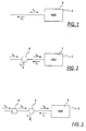
- Fig. 1 is a schematic illustration of a stimulated Brillouin scattering (SBS) wavelength-shifting device 2.
- SBS stimulated Brillouin scattering
- An incident beam of wavelength ⁇ 0 propagates from left to right towards an SBS device 2 made of a material 4, which material could be constituted by an optical fiber, a bulk material, a liquid, or other optical material. Due to SBS, a reflected beam with a slightly different wavelength ⁇ 1 emerges back from the SBS material 4.
- the fibers to be used may have a small core area and may be selected from the group comprising photonic bandgap fibers, dispersion compensating fibers, or high numerical aperture fibers.
- a suitable laser to generate the incident beam of wavelength ⁇ 0 is S3FC1550 made by Thorlabs in New Jersey.
- One example of a suitable high numerical aperture fiber is a 500m long fiber having a 3 ⁇ m core diameter made of GeO 2 doped silica (approximately 35% by weight) and having a refractive index of 1.479 and a cladding made of silica and having a refractive index of 1.447.
- this fiber receives a light beam having a wavelength ⁇ 0 of 1550nm. at a power level above its threshold value, it produces a reflected beam having a wavelength ⁇ 1 of 1550.075mn. The difference ⁇ between the two wavelengths is 0.075nm.
- This particular fiber has an SBS threshold of about 100miliwatts, and thus it produces a shifted reflected beam in response to any incident beam having an input power above the threshold value.
- Fig. 2 shows a schematic illustration of an SBS device 2 with an optical beam splitter or circulator 6, in which, similar to the device of Fig. 1, an incident beam of wavelength ⁇ 0 propagates from left to right. The beam passes through the optical beam splitter or circulator 6, towards the SBS material 4. Here again, a reflected beam of wavelength ⁇ 1 is created. The optical beam splitter or circulator 6 does not transmit the reflected beam, but rather reflects it to a different path, schematically shown as downwards.
- a suitable splitter or circulator when operating in the wavelength range of 1530nm to 1570nm are the Models 10202A splitter or 6015-3 circulator available from Thorlabs in New Jersey.
- FIG. 3 A configuration which also includes an optical amplifier 8, is shown in Fig. 3.
- the incident beam (at the left) of wavelength ⁇ 0 has relatively low power.
- an optical amplifier 8 which could be an optical fiber, a bulk material or other optical material, to obtain a beam having the same wavelength but higher power.
- This higher power beam is then incident on an SBS device 2, similar to that shown in Fig. 2.
- One example of a suitable optical amplifier when operating in the range of 1530nm to 1565nm is the Model AMP-FL8011-CB-21 amplifier available from Thorlabs in New Jersey.
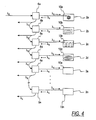
- Fig. 4 is a schematic illustration of a cascaded system according to the present invention, comprising a plurality of SBS devices 2a-2n each of which receives an input beam from one of a plurality of splitters 6a-6n.
- Each output beam having a specific wavelength, emerging from an SBS device 2 serves both as one of the output beams ⁇ 1 - ⁇ n for the cascaded system, and as a source beam for the next SBS device in the cascade.
- multiple beams ⁇ 1 - ⁇ n each having a distinct wavelength, are obtained.
- each of the individual SBS devices 2a-2n may be composed of an optical fiber wound around a spool to form a fiber coil 10a.
- a suitable SBS device is formed by winding 500 turns of the optical fiber identified above on a cylindrical core having a diameter of 15cm with little or no tension on the fiber in the final coil 10a.
- the same effect can be achieved by an optical fiber, or any other flexible, semi-rigid or rigid waveguide providing a continuously patterned optical path in any desired configuration.
- the fiber may follow a spiral path as in the case of fiber 10d in Fig. 4,or a meandering path as in the case of fiber 10c, or a path following straight lines as in the case of fiber 10a.
- Temperature stabilization is obtained by the proper design and selection of the fiber material parameters (mostly temperature dependence of the refractive index) and the spool materials (mostly expansion coefficients) and dimensions.
- an incident beam having a wavelength ⁇ 0 of 1550nm. produces a "comb" of output signals having wavelengths ⁇ 1 - ⁇ n of 1550.075nm, 1550.150nm, 1550.225nm, 1550.300nm, 1550.375nm, etc.
- the relative spacing of the output signals in this comb remains stable up to ⁇ 0.005nm over a temperature range of 0 to 40 °C..
- the entire comb might shift due to wavelength changes of the source, caused by fluctuations in temperature, but the spacing between the multiple signals comprising the comb remains stable.
- An illustration of experimental results showing 5 output lines is shown in Fig. 23.
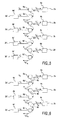
- Fig. 5 is a schematic illustration of a cascaded configuration of SBS devices 2a-2d, each of which comprises first and second wavelength-shifting components, such as 2a and 2a', connected in series and having refractive indices that vary in opposite directions in response to temperature changes.
- the alternating devices 2a and 2a', 2b and 2b', 2c and 2c', and 2d and 2d' are composed of two different materials such as 4a and 4a', one having a refractive index increasing with temperature, and the other having a refractive index decreasing with temperature.
- An incident light beam of wavelength ⁇ 0 is applied to SBS material 4a to produce a reflected beam of wavelength ⁇ 1 .
- This reflected beam is then applied to the second SBS material 4a' via first and second splitters 6a and 6a' to produce a second reflected beam of wavelength ⁇ 1 .
- This second beam is removed by the second splitter 6' to produce a first output of wavelength ⁇ 1 '.
- temperature-constant shifts or spacings are obtained because any shift in the wavelength ⁇ 1 due to a temperature change that alters the refractive index of material 4a, is substantially nullified or cancelled by a similar shift in the wavelength ⁇ 1 ' in the opposite direction due to the effect of that same temperature change on the refractive index of material 4a'.
- the two materials 4a and 4a' may be BK10 and PK50 Schott glasses, which have refractive indices that increase and decrease with temperature as follows: Table of Absolute Refractive Indices Change with Temperature material. dn/dT Material 4a BK10 +1.6 x 10 -6 °C -1 Material 4a' PK50 -1.6 x 10 -6 °C -1
- the wavelength shifts of the reflected output signals ⁇ 1 - ⁇ 4 produced by those devices increase proportionally to the increase in n .
- the wavelengths shifts of the reflected output signals ⁇ 1 '- ⁇ 4 ' produced by those devices decrease proportionally to the decrease in n .
- the wavelength shift of the output of the first device 2a increases while the wavelength shift of the output of the second device 2a' decreases. The sum of the shifts remains substantially constant with temperature, resulting in substantially temperature-independent wavelengths.
- Fig. 6 shows a cascaded configuration similar to that of Fig. 5, with optical amplifiers 8a-8c added between the two splitters associated with each pair of different SBS devices, such as the two splitters 6a and 6a' associated with the pair of SBS devices 2a and 2a'.
- optical amplifiers 8a-8c added between the two splitters associated with each pair of different SBS devices, such as the two splitters 6a and 6a' associated with the pair of SBS devices 2a and 2a'.
- Other numbers and placements of amplifiers 8 along the beam paths are also possible.
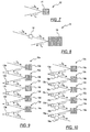
- Fig. 7 illustrates an acousto-optical wavelength-shifting device 12, in which an input beam of wavelength ⁇ 0 is incident upon an acousto-optical material 14.
- the scattered or reflected beam, propagating from right to left, has a slightly different output wavelength ⁇ 1 .
- FIG. 8 A similar acousto-optical wavelength-shifting device 12, with the addition of an optical amplifier 16 for the input beam, is shown in Fig. 8.
- the incident beam (at the left) of wavelength ⁇ 0 has relatively low power (watts/cm 2 ).
- This higher power beam is then incident on an acousto-optical wavelength-shifting device 12, similar to that shown in Fig. 7, to produce an output beam of wavelength ⁇ 1 .
- Fig. 9 is a schematic illustration of a cascaded configuration of acousto-optical wavelength-shifting devices 12a-12e made of acousto-optical materials 14a-14e, comprising a multiplicity of the devices shown in Fig. 7.
- the first device 12a receives an input beam of wavelength ⁇ 0 and produces an output beam of wavelength ⁇ 1 .
- the output beams of the devices 12a-12e in the cascade are passed through respective splitters 13a-13e so that each beam becomes an output and is also used as an input beam for the next such device in the cascade, thereby producing a series of wavelength-shifted output beams having wavelengths ⁇ 1 - ⁇ 5 .
- Each output beam emerging from the acousto-optical wavelength-shifting devices 12a-12e has a specific wavelength, and serves both as one of the output beams for the cascaded system, and as a source beam for the next acousto-optical wavelength-shifting device 12. In this manner, multiple output beams, each having a distinct wavelength, are obtained.
- Fig. 10 shows a cascaded configuration similar to that of Fig. 9, with the addition of optical amplifiers 18a-18d in the respective input lines to the individual acousto-optical wavelength-shifting devices 12b-12e following the first device 12a.
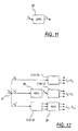
- Fig. 11 is a schematic illustration of an optical parametric oscillator (OPO) 20.
- OPO optical parametric oscillator
- an incident beam with a wavelength ⁇ 0 is transformed into a beam having a different wavelength ⁇ 1 .
- the wavelength change effected by the OPO can be significantly larger than that obtained using SBS or acousto-optical devices.
- a suitable OPO is KTP (available from Raicol Crystals) which produces a light beam having a wavelength ⁇ 1 of 1540 to 1570nm in response to an incident beam having a waveleng ⁇ 0 of 1060nm.
- Fig. 12 illustrates a system having a combination of OPOs 20 and wavelength-shifting devices that can be either SBS devices 2 or acousto-optical devices 12.
- a single input beam, of wavelength ⁇ 0 is used.
- the beam is first split into three beam portions ⁇ 0 ', ⁇ 0 ", ⁇ 0 ''' using a splitter 21.
- a suitable device for splitting a light beam in this manner is a Model S-P-15-AV-0103-A-B-0 splitter made by Global Opticom located in California.
- the first beam portion ⁇ 0 ' is applied directly into a wavelength-shifting SBS device 2 or acousto-optical device 12, to obtain a multiplicity of beams having the wavelengths ⁇ 1 - ⁇ 3 .
- These three wavelengths may be produced by a cascade arrangement of the type described above in connection with Fig. 4, 5 or 6.
- the second beam portion ⁇ 0 " is first transformed by an OPO 20 to a beam having wavelength ⁇ 4 , which in turn is incident on another cascade arrangement of wavelength-shifting SBS devices 2 or acousto-optical devices 12, to obtain a multiplicity of beams having wavelengths ⁇ 5 - ⁇ 7 .
- the third beam portion ⁇ 0 ''' is first applied directly into a cascade arrangement of wavelength-shifting SBS devices 2 or acousto-optical devices 12, to obtain a multiplicity of beams having wavelengths ⁇ 8 - ⁇ 10 ; these beams are then transformed by an OPO 20 to obtain output beams having wavelengths ⁇ 11 - ⁇ 13 .
- the OPO 20 is enabled to amplify and wavelength-shift three different beams simultaneously. Other combinations of OPO 20, SBS devices 2 and acousto-optical wavelength-shifting devices 12 are also possible.
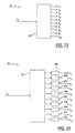
- Fig. 13 is a schematic illustration of a system 22, wherein a single input beam of wavelength ⁇ 0 is transformed into a series of separated beams having different output wavelengths; in this specific embodiment, ten wavelengths ⁇ 1 - ⁇ 10 .
- the system 22 may include cascaded SBS devices or cascaded acousto-optical wavelength-shifting devices, or a combination of those with OPOs
- the input wavelength ⁇ 0 may be equal to one of the output wavelengths ⁇ 1 - ⁇ 10 .
- Fig. 14 is a schematic illustration of a system 22, wherein a single input beam having a wavelength ⁇ 0 is transformed into a series of separated beams having different output wavelengths ⁇ 1 - ⁇ 10 as shown in Fig. 13, but each of the output beams is modulated by one of a group of parallel modulators 24a-24j.
- the purpose of the modulation is to use each optical output as a carrier for information that is combined with the carrier via the modulation process.
- One suitable modulator for this purpose is the Model 1976 EAM modulator made by Alcatel located in France.
- the number of modulators is the same as the number of output beams.
- groups of output beams can be modulated together by the same modulator, to obtain a broadcast-like transmission.
- the system 22 may include cascaded SBS devices, cascaded acousto-optical wavelength-shifting devices, or a combination of those with OPOs.
- the input wavelength ⁇ 0 may be the same as one of the output wavelengths ⁇ 1 - ⁇ 10 .
- the multiple-wavelength outputs from any of the systems described above are used in an optical communication system, it is preferred to transmit multiple wavelengths simultaneously in a single optical fiber or waveguide in at least a portion of the communication system.
- This multiplexing of multiple wavelengths in a single fiber can be accomplished by simply launching or coupling the different wavelengths into the same fiber or waveguide. Then at the receiving end of a communication link, it is typically necessary to re-separate or de-multiplex the different wavelengths.
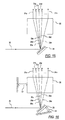
- Fig. 15 is a schematic illustration of an optical de-multiplexing system.
- An incident beam of light 26 composed of a multitude of wavelengths, is illuminated on a wavelength-dispersive component 28, such as a grating or a prism.
- a wavelength-dispersive component 28 such as a grating or a prism.
- One suitable component for this purpose is the Model NT43-209 grating made by Edmund Optics located in New Jersey.
- Component 28 splits, by diffraction, the incident beam 26 into a series of separate beams 29a-29n, each having a different wavelength. These beams 29a-29n, each propagating in a slightly different direction, are incident upon a receiver 30 that couples the separate beams into corresponding different output fibers 31a-31n, causing different output fibers to contain beams of different wavelengths.
- One suitable receiver for this purpose is the Model 1554 receiver made by New Focus located in California.
- Each separate beam 29 is preferably coupled into a separate fiber 31, representing
- the receiver 30 can be physically moved by an actuator 32 to adjust the relative positions of the grating 28 and the receiver 30 in order to match the separate beams 29a-29n with the desired output fibers 31a-31n.
- the actuator 32 is preferably a controllable actuator such as a Model 8301 linear actuator made by New Focus located in California.
- the diffraction component 28 can be tilted by a controllable actuator 34 in order to change the direction of the diffracted beams 29a-29n so as to match the incident wavelengths to given fibers 31a-31n representing the different output channels.
- Either of the two actuators 32 and 34 may be alone, or they may be used in combination with each other.
- Fig. 17 illustrates an optical de-multiplexing system in which the incident beam of light 26 passes through an acousto-optical wavelength-shifting device 36, which changes the wavelength so that slightly different wavelengths are diffracted from component 28, leading to a slight change of the diffraction angles of the different wavelengths.
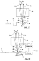
- Fig. 18 is a schematic illustration of an optical de-multiplexing system having a feedback control loop 38, wherein two detectors 40, 42 are positioned on two sides of the desired position of one of the separate beams 29a-29n in the receiver 30 to detect at least one characteristic of that light beam.
- the two detectors 40, 42 form part of a feedback control loop for controlling the actuator 34 that controls the tilt angle of the diffraction component 28 to change the direction of the diffracted beams 29a-29n.
- each of the two detectors 40 and 42 detects the optical power level at one side of the beam 29n and produces a control signal representing the detected power level to a comparator 43.
- the comparator 43 serves as a controller that produces an output signal representing the magnitude of the difference between the two signals from the detectors 40 and 42. The polarity of this output signal preferably indicates which of the two detectors detected the higher power level.
- the output signal from the comparator 43, within the control loop 38, is supplied to the controllable actuator 34 to adjust the tilt of the grating 28 until substantially equal power levels are detected in the two detectors 40, 42.
- the electrical polarity of the signal supplied to the actuator 34 determines the direction of movement of the actuator, which in turn determines whether the tilt angle is increased or decreased.
- specific modulation or specific data formats in the control loop 38 may differentiate it from other channels, so the control loop can be readily found.
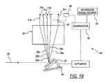
- Fig. 19 illustrates an optical de-multiplexing system having a feedback control loop 44, wherein an optical splitter 47 diverts a portion of the power in one of the output fibers 31n into a single detector 46 that detects the power level in that particular output fiber (namely, the control channel).
- the detector 46 supplies a signal representing the detected power level to a comparator 48 that also receives a fixed reference signal from a source 49, and produces an output signal representing the magnitude of any difference between the detector signal and the reference signal.
- the reference signal represents a desired power level.
- the polarity of the output signal from the comparator 48 preferably indicates whether the detector signal is greater than or less than the reference signal.
- the output signal from the comparator 48 is supplied to the controllable actuator 34 that controls the tilt angle of the grating 28, causing the actuator 34 to adjust the tilt of the grating 28 until the signal from the detector 46 is substantially equal to the reference signal.
- the electrical polarity of the signal supplied to the actuator 34 deterrnines the direction of movement of the actuator, which in turn determines whether the tilt angle of the grating 28 is increased or decreased.
- the control loop 44 thus maximizes or optimizes the output power level in channel 48, thereby also optimizing the power levels of all the other diffracted light beams.
- Control channel 48 may have a specific, known modulation, so as to allow for its identification, using techniques such as matched filtering.
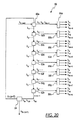
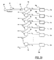
- Fig. 20 illustrates a multi-cascaded, multi-wavelength optical source 50.
- a beam having wavelength ⁇ 0 injects into the first wavelength-shifting component 52a of a cascaded array of eight such components 52a-52h, which may be composed of SBS devices or acousto-optical wavelength-shifting devices, or a combination of these, with or without optical amplifiers.
- Each of the wavelength-shifting components 52a-52h introduces a new wavelength, to obtain, in a cascaded configuration, the first series of wavelengths ⁇ 1 - ⁇ 8 .
- Each of the wavelength-shifting components 52a-52h is capable of simultaneously producing multiple outputs of different wavelengths in response to simultaneous input beams having different wavelengths, provided the wavelengths of the input beams are sufficiently spaced from each other. For example, if the spacing between successive output wavelengths produced by the wavelength-shifting components 52a-52h is 0.075nm, the spacing between the two input wavelengths ⁇ 0 and ⁇ 9 to component 52a is 0.6nm, which is sufficient to enable the components 52a to produce simultaneous outputs of different wavelengths in response to the simultaneous inputs of different wavelengths ⁇ 1 , ⁇ 10 . The same is true for all the other components 52b-52h as well, because the spacing between the wavelengths of the simultaneous inputs to each of these components will also be 0.6nm. This enables its separation using available and low price dielectric filter demultiplexer.
- the feedback loop between the output of the last wavelength-shifting component 52h and the input of the first component 52a includes a filter 54 that allows only a selected band of wavelengths to pass (for example, wavelengths below ⁇ 8n where n is below a threshold T, thus limiting the number of recirculations to n).
- a filter 54 that allows only a selected band of wavelengths to pass (for example, wavelengths below ⁇ 8n where n is below a threshold T, thus limiting the number of recirculations to n).
- the feedback is resumed with the output wavelength ⁇ 8 produced by the last wavelength-shifting device 52h in response to the supply of only the wavelength ⁇ 0 to the first device 52a.
- This first series of outputs is again followed by subsequent series of outputs until the pass band of the filter 54 is again exceeded, at which point the cycle repeats again.
- each of the wavelength-shifting components 52a-52h now contains several different wavelengths, according to the number of series. (In the embodiment shown in Fig. 20, there are three series.)
- each of the output beams is passed through a demultiplexer 56a-56h of the simple type, for example a dielectric filter set, thus producing a large number of separated wavelengths with a relatively small number of components.
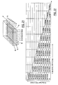
- a wavelength cascade having 10 GHz freduency spacing between each pair of neighboring wavelengths, is generated by means of an SBS technique.
- the wavelength cascade shown in Fig. 21 consists of ten successive spectral lines 60-69, represented by the first column in Fig. 22 (hereinafter, "type 1 cascade").
- type 1 cascade Each one of the lines in the type 1 cascade serves as a source for generating, also by means of SBS, a second wavelength cascade having 11 GHz spacing and nine successive spectral lines 70-78 (hereinafter, "type 2 cascade”).
- ten type 2 cascades can be generated. All of the lines in the single type 1 cascade and the ten type 2 cascades present a set of one hundred spectral lines having 1 GHz spacing between each two neighboring lines. Each spectral line exists in a separate fiber, allowing separate modulation for each line, the lines thus serving as a multiple wavelength source.
- the embodiment shown is not limited to one hundred spectral lines; similarly, it is not limited to 1 GHz spacing; it is, rather, a general illustration for any number of lines and any spacing between them.
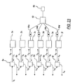
- Fig. 23 is a schematic illustration of a cascaded system with optical seeding.
- the cascaded system is similar to that shown in Fig. 4.
- seeding light sources in this case a single light source 80
- a laser, a light-emitting diode, or an amplified spontaneous emission source is coupled to some or all of six SBS devices 2a-2f producing six output beams having wavelengths ⁇ 1 - ⁇ 6 .
- the seeding light from the source 80 enhances the power and/or the stability of the light beams emitted from the four seeded Brillouin devices 2c-2f.
- a device 82 such as a coupler, a splitter or a filter couples the source to the Brillouin devices 2c-2f to be seeded.
- the device 82 may be omitted if the light source 80 is connected to only a single Brillouin device.
- Optical isolators 84a-84d are connected between the device 82 and the respective Brillouin devices 2c-2f, to prevent light beams from propagating from the Brillouin devices toward the seed light source 80.
- Fig. 24 is a graph of the measured output of an optical spectrum analyzer.
- the input to the optical spectrum analyzer consisted of five different wavelengths, generated by cascading of SBS devices. These five wavelengths, each propagated in a separate fiber, were combined using an optical splitter, in order to be measured together by the optical spectrum analyzer. As evident from the graph, there are five distinct wavelengths, with similar spacing between them.
- Fig. 25 is a schematic illustration of a system with a backup laser 90 to the first laser source 91.
- the backup laser source 90 which could be a fixed wavelength source or a tunable laser source, emits light having a wavelength of ⁇ 0 .
- the optical switch 92 routes the beam emitted from the backup laser 90 into the first coupler of circulator 6a.
- a failure in the first laser source does not result in a complete system failure.
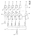
- Fig. 26 is a schematic illustration of a system with a tunable backup laser 94.
- the tunable backup laser source 94 can emit any of the wavelengths in the cascaded configuration ( ⁇ 1 - ⁇ n ).
- the tunable laser source 94 is tuned to ⁇ 3 , and the switch 96 routes the beam from the tunable source 94 to the switch or coupler 98c, which in turn routes it to the coupler or circulator 6d.
- all the following outputs ⁇ 4 - ⁇ n remain as they should be. Note that without such backup source, a failure in one of the cascaded elements would immediately cause failure in all subsequent lines.
Landscapes
- Physics & Mathematics (AREA)
- General Physics & Mathematics (AREA)
- Optics & Photonics (AREA)
- Electromagnetism (AREA)
- Engineering & Computer Science (AREA)
- Computer Networks & Wireless Communication (AREA)
- Signal Processing (AREA)
- Nonlinear Science (AREA)
- Optical Communication System (AREA)
Applications Claiming Priority (6)
| Application Number | Priority Date | Filing Date | Title |
|---|---|---|---|
| IL14172701 | 2001-02-28 | ||
| IL141727A IL141727A (en) | 2001-02-28 | 2001-02-28 | Optical systems |
| IL14449801 | 2001-07-23 | ||
| IL14449801A IL144498A0 (en) | 2001-07-23 | 2001-07-23 | Optical systems |
| IL14672301 | 2001-11-25 | ||
| IL14672301A IL146723A0 (en) | 2001-11-25 | 2001-11-25 | Optical systems |
Publications (3)
| Publication Number | Publication Date |
|---|---|
| EP1237305A2 true EP1237305A2 (fr) | 2002-09-04 |
| EP1237305A3 EP1237305A3 (fr) | 2004-11-03 |
| EP1237305B1 EP1237305B1 (fr) | 2012-04-25 |
Family
ID=27271947
Family Applications (1)
| Application Number | Title | Priority Date | Filing Date |
|---|---|---|---|
| EP02004672A Expired - Lifetime EP1237305B1 (fr) | 2001-02-28 | 2002-02-28 | Source de lumière à longueurs d'ondes multiples |
Country Status (3)
| Country | Link |
|---|---|
| US (1) | US6847477B2 (fr) |
| EP (1) | EP1237305B1 (fr) |
| CA (1) | CA2373952A1 (fr) |
Cited By (45)
| Publication number | Priority date | Publication date | Assignee | Title |
|---|---|---|---|---|
| WO2019079642A1 (fr) | 2017-10-19 | 2019-04-25 | Innovusion Ireland Limited | Lidar à plage dynamique étendue |
| CN110426372A (zh) * | 2019-07-16 | 2019-11-08 | 南昌航空大学 | 一种扫频式布里渊散射体弹性模量成像检测方法 |
| US11289873B2 (en) | 2018-04-09 | 2022-03-29 | Innovusion Ireland Limited | LiDAR systems and methods for exercising precise control of a fiber laser |
| US11300683B2 (en) | 2016-12-30 | 2022-04-12 | Innovusion Ireland Limited | Multiwavelength LiDAR design |
| US11391823B2 (en) | 2018-02-21 | 2022-07-19 | Innovusion, Inc. | LiDAR detection systems and methods with high repetition rate to observe far objects |
| US11422267B1 (en) | 2021-02-18 | 2022-08-23 | Innovusion, Inc. | Dual shaft axial flux motor for optical scanners |
| US11493601B2 (en) | 2017-12-22 | 2022-11-08 | Innovusion, Inc. | High density LIDAR scanning |
| US11555895B2 (en) | 2021-04-20 | 2023-01-17 | Innovusion, Inc. | Dynamic compensation to polygon and motor tolerance using galvo control profile |
| US11567182B2 (en) | 2018-03-09 | 2023-01-31 | Innovusion, Inc. | LiDAR safety systems and methods |
| US11579258B1 (en) | 2018-08-30 | 2023-02-14 | Innovusion, Inc. | Solid state pulse steering in lidar systems |
| US11579300B1 (en) | 2018-08-21 | 2023-02-14 | Innovusion, Inc. | Dual lens receive path for LiDAR system |
| US11604279B2 (en) | 2017-01-05 | 2023-03-14 | Innovusion, Inc. | MEMS beam steering and fisheye receiving lens for LiDAR system |
| US11609336B1 (en) | 2018-08-21 | 2023-03-21 | Innovusion, Inc. | Refraction compensation for use in LiDAR systems |
| US11614526B1 (en) | 2018-08-24 | 2023-03-28 | Innovusion, Inc. | Virtual windows for LIDAR safety systems and methods |
| US11614521B2 (en) | 2021-04-21 | 2023-03-28 | Innovusion, Inc. | LiDAR scanner with pivot prism and mirror |
| US11624806B2 (en) | 2021-05-12 | 2023-04-11 | Innovusion, Inc. | Systems and apparatuses for mitigating LiDAR noise, vibration, and harshness |
| US11644543B2 (en) | 2018-11-14 | 2023-05-09 | Innovusion, Inc. | LiDAR systems and methods that use a multi-facet mirror |
| US11662439B2 (en) | 2021-04-22 | 2023-05-30 | Innovusion, Inc. | Compact LiDAR design with high resolution and ultra-wide field of view |
| US11662440B2 (en) | 2021-05-21 | 2023-05-30 | Innovusion, Inc. | Movement profiles for smart scanning using galvonometer mirror inside LiDAR scanner |
| US11675050B2 (en) | 2018-01-09 | 2023-06-13 | Innovusion, Inc. | LiDAR detection systems and methods |
| US11675053B2 (en) | 2018-06-15 | 2023-06-13 | Innovusion, Inc. | LiDAR systems and methods for focusing on ranges of interest |
| US11675055B2 (en) | 2019-01-10 | 2023-06-13 | Innovusion, Inc. | LiDAR systems and methods with beam steering and wide angle signal detection |
| US11762065B2 (en) | 2019-02-11 | 2023-09-19 | Innovusion, Inc. | Multiple beam generation from a single source beam for use with a lidar system |
| US11768294B2 (en) | 2021-07-09 | 2023-09-26 | Innovusion, Inc. | Compact lidar systems for vehicle contour fitting |
| US11782131B2 (en) | 2016-12-31 | 2023-10-10 | Innovusion, Inc. | 2D scanning high precision LiDAR using combination of rotating concave mirror and beam steering devices |
| US11789132B2 (en) | 2018-04-09 | 2023-10-17 | Innovusion, Inc. | Compensation circuitry for lidar receiver systems and method of use thereof |
| US11789128B2 (en) | 2021-03-01 | 2023-10-17 | Innovusion, Inc. | Fiber-based transmitter and receiver channels of light detection and ranging systems |
| US11796645B1 (en) | 2018-08-24 | 2023-10-24 | Innovusion, Inc. | Systems and methods for tuning filters for use in lidar systems |
| US11808888B2 (en) | 2018-02-23 | 2023-11-07 | Innovusion, Inc. | Multi-wavelength pulse steering in LiDAR systems |
| EP4152647A4 (fr) * | 2020-05-29 | 2023-11-08 | Huawei Technologies Co., Ltd. | Source de lumière composée et son procédé de production |
| US11860316B1 (en) | 2018-08-21 | 2024-01-02 | Innovusion, Inc. | Systems and method for debris and water obfuscation compensation for use in LiDAR systems |
| US11871130B2 (en) | 2022-03-25 | 2024-01-09 | Innovusion, Inc. | Compact perception device |
| US11927696B2 (en) | 2018-02-21 | 2024-03-12 | Innovusion, Inc. | LiDAR systems with fiber optic coupling |
| US11947047B2 (en) | 2017-01-05 | 2024-04-02 | Seyond, Inc. | Method and system for encoding and decoding LiDAR |
| US11965980B2 (en) | 2018-01-09 | 2024-04-23 | Innovusion, Inc. | Lidar detection systems and methods that use multi-plane mirrors |
| US11977185B1 (en) | 2019-04-04 | 2024-05-07 | Seyond, Inc. | Variable angle polygon for use with a LiDAR system |
| US11988773B2 (en) | 2018-02-23 | 2024-05-21 | Innovusion, Inc. | 2-dimensional steering system for lidar systems |
| US12038534B2 (en) | 2021-11-24 | 2024-07-16 | Innovusion (suzhou) Co., Ltd. | Motor for on-vehicle lidar, on-vehicle lidar, and vehicle |
| US12050288B2 (en) | 2017-01-05 | 2024-07-30 | Seyond, Inc. | High resolution LiDAR using high frequency pulse firing |
| US12061289B2 (en) | 2021-02-16 | 2024-08-13 | Innovusion, Inc. | Attaching a glass mirror to a rotating metal motor frame |
| US12072447B2 (en) | 2021-04-22 | 2024-08-27 | Seyond, Inc. | Compact LiDAR design with high resolution and ultra-wide field of view |
| US12085673B2 (en) | 2018-02-23 | 2024-09-10 | Seyond, Inc. | Distributed LiDAR systems |
| US12204033B2 (en) | 2022-03-25 | 2025-01-21 | Seyond, Inc. | Multimodal detection with integrated sensors |
| US12313788B1 (en) | 2018-10-09 | 2025-05-27 | Seyond, Inc. | Ultrashort pulses in LiDAR systems |
| US12468017B2 (en) | 2021-10-15 | 2025-11-11 | Seyond, Inc. | Integrated mirror motor galvanometer |
Families Citing this family (14)
| Publication number | Priority date | Publication date | Assignee | Title |
|---|---|---|---|---|
| KR100487190B1 (ko) * | 2003-04-22 | 2005-05-04 | 삼성전자주식회사 | 라만 광증폭기 |
| EP1489763B1 (fr) * | 2003-06-19 | 2006-04-12 | Alcatel | Amplificateur optique, système de transmission et procédé d'optimisation |
| US20050185907A1 (en) * | 2004-02-25 | 2005-08-25 | Byren Robert W. | Stimulated brillouin scattering phase conjugate mirror utilizing photonic bandgap guide and method |
| FR2867619B1 (fr) * | 2004-03-12 | 2006-06-23 | Thales Sa | Dispositif de decalage de frequence dans un chemin optique a source laser pulsee |
| FR2867620B1 (fr) * | 2004-03-12 | 2008-10-24 | Thales Sa | Dispositif de decalage de frequence dans un chemin optique a source laser continue |
| US7330657B2 (en) * | 2004-04-01 | 2008-02-12 | Bookham Technology Plc | Method to demultiplex wavelengths of light |
| US7580323B2 (en) * | 2005-10-21 | 2009-08-25 | The United States Of America As Represented By The Administrator Of The National Aeronautics And Space Adninistration | Tunable optical assembly with vibration dampening |
| GB2472987A (en) | 2009-08-24 | 2011-03-02 | Cambridge Entpr Ltd | Composite optical materials, uses of composite optical materials and methods for the manufacture of composite optical materials |
| KR101087263B1 (ko) * | 2009-12-24 | 2011-11-29 | 한국과학기술원 | 파장 가변 레이저의 발진 파장을 조절하는 장치 및 방법, 및 이를 구비한 파장 분할 다중방식 수동형 광 가입자망 |
| JP5931921B2 (ja) | 2011-01-12 | 2016-06-08 | ケンブリッジ エンタープライズ リミテッド | 複合光学材料の製造 |
| US10036904B1 (en) * | 2014-03-26 | 2018-07-31 | Inphi Corporation | Method and system for integrated differential electro-absorption modulator device |
| FR3054663B1 (fr) * | 2016-07-28 | 2018-09-07 | Stmicroelectronics (Crolles 2) Sas | Procede de caracterisation de dispositifs photoniques, et dispositif associe. |
| GB201622169D0 (en) | 2016-12-23 | 2017-02-08 | Univ Court Of The Univ Of Edinburgh The | Receiver and associated mobile communications device |
| US11218220B2 (en) * | 2019-05-14 | 2022-01-04 | Infinera Corporation | Out-of-band communication channel for subcarrier-based optical communication systems |
Citations (1)
| Publication number | Priority date | Publication date | Assignee | Title |
|---|---|---|---|---|
| JPH1115032A (ja) | 1997-06-25 | 1999-01-22 | Tokyo Electric Power Co Inc:The | 波長多重伝送用光周波数変換器及び波長多重伝送用光源 |
Family Cites Families (28)
| Publication number | Priority date | Publication date | Assignee | Title |
|---|---|---|---|---|
| US4764930A (en) | 1988-01-27 | 1988-08-16 | Intelligent Surgical Lasers | Multiwavelength laser source |
| US5099147A (en) * | 1990-11-05 | 1992-03-24 | Hughes Aircraft Company | Raman converter with variable wavelength distribution |
| JPH05333395A (ja) * | 1992-04-03 | 1993-12-17 | Fuji Photo Film Co Ltd | 光波長変換装置 |
| US5463493A (en) | 1993-01-19 | 1995-10-31 | Mvm Electronics | Acousto-optic polychromatic light modulator |
| US5524012A (en) | 1994-10-27 | 1996-06-04 | New Focus, Inc. | Tunable, multiple frequency laser diode |
| GB9503301D0 (en) | 1995-02-20 | 1995-04-12 | Secr Defence | Laser amplifier |
| US5710653A (en) | 1995-03-06 | 1998-01-20 | Fiber Optic Network Solutions Corp. | Linear multi-output optical transmitter system |
| US5689363A (en) | 1995-06-12 | 1997-11-18 | The Regents Of The University Of California | Long-pulse-width narrow-bandwidth solid state laser |
| US5828477A (en) | 1995-11-16 | 1998-10-27 | Harmonic Lightwaves, Inc. | Multi-tone phase modulation for light wave communication system |
| JP3055452B2 (ja) | 1996-01-10 | 2000-06-26 | 日本電気株式会社 | 光伝送路監視方法 |
| FR2744292B1 (fr) | 1996-01-29 | 1998-04-30 | Menigaux Louis | Composant d'emission laser multi-longueur d'onde |
| US5953139A (en) | 1996-03-06 | 1999-09-14 | Cfx Communications Systems, Llc | Wavelength division multiplexing system |
| US5854802A (en) | 1996-06-05 | 1998-12-29 | Jin; Tianfeng | Single longitudinal mode frequency converted laser |
| GB9626099D0 (en) | 1996-12-16 | 1997-02-05 | King S College London | Distributed strain and temperature measuring system |
| FR2757722B1 (fr) * | 1996-12-23 | 1999-03-19 | France Telecom | Multiplexeur et/ou demultiplexeur optique independant de la temperature |
| US5987201A (en) | 1997-02-12 | 1999-11-16 | Applied Fiber Optics, Inc. | Apparatus and method of making a fused dense wavelength-division multiplexer |
| US5963567A (en) | 1997-02-13 | 1999-10-05 | Lucent Technologies, Inc. | Multi-wavelength laser source |
| FR2760574B1 (fr) | 1997-03-04 | 1999-05-28 | Thomson Csf | Laser unipolaire multi-longueurs d'ondes |
| JPH11136214A (ja) | 1997-10-28 | 1999-05-21 | Matsushita Electric Ind Co Ltd | 波長多重光伝送システム |
| US6144482A (en) | 1997-11-14 | 2000-11-07 | Neos Technologies, Inc. | Acousto-optic modulator for selective extraction of one or more wavelengths from randomly polarized polychromatic light beam |
| JP4180140B2 (ja) | 1998-02-12 | 2008-11-12 | 富士通株式会社 | 多波長光源 |
| US6125228A (en) | 1998-03-04 | 2000-09-26 | Swales Aerospace, Inc. | Apparatus for beam splitting, combining wavelength division multiplexing and demultiplexing |
| US6388782B1 (en) | 1998-06-01 | 2002-05-14 | Sarnoff Corporation | Multi-wavelength dense wavelength division multiplexed optical switching systems |
| US6014237A (en) | 1998-06-01 | 2000-01-11 | Sarnoff Corporation | Multiwavelength mode-locked dense wavelength division multiplexed optical communication systems |
| US5999291A (en) | 1998-06-02 | 1999-12-07 | Telcordia Technologies, Inc. | Centralized wavelength distribution for wavelength division multiplexed systems |
| US6130971A (en) | 1998-08-06 | 2000-10-10 | Avanex Corporation | Fiber optic dense wavelength division multiplexer with a phase differential method of wavelength separation utilizing a polarization beam splitter and a nonlinear interferometer |
| US6192058B1 (en) | 1998-09-18 | 2001-02-20 | Sarnoff Corporation | Multiwavelength actively mode-locked external cavity semiconductor laser |
| US6389044B1 (en) | 1999-07-02 | 2002-05-14 | Corning Incorporated | Multi-wavelength laser usable for WDM applications and interferometric sensors |
-
2002
- 2002-02-27 US US10/084,796 patent/US6847477B2/en not_active Expired - Lifetime
- 2002-02-28 CA CA002373952A patent/CA2373952A1/fr not_active Abandoned
- 2002-02-28 EP EP02004672A patent/EP1237305B1/fr not_active Expired - Lifetime
Patent Citations (1)
| Publication number | Priority date | Publication date | Assignee | Title |
|---|---|---|---|---|
| JPH1115032A (ja) | 1997-06-25 | 1999-01-22 | Tokyo Electric Power Co Inc:The | 波長多重伝送用光周波数変換器及び波長多重伝送用光源 |
Cited By (71)
| Publication number | Priority date | Publication date | Assignee | Title |
|---|---|---|---|---|
| US11300683B2 (en) | 2016-12-30 | 2022-04-12 | Innovusion Ireland Limited | Multiwavelength LiDAR design |
| US11953601B2 (en) | 2016-12-30 | 2024-04-09 | Seyond, Inc. | Multiwavelength lidar design |
| US11782132B2 (en) | 2016-12-31 | 2023-10-10 | Innovusion, Inc. | 2D scanning high precision LiDAR using combination of rotating concave mirror and beam steering devices |
| US11782131B2 (en) | 2016-12-31 | 2023-10-10 | Innovusion, Inc. | 2D scanning high precision LiDAR using combination of rotating concave mirror and beam steering devices |
| US12276755B2 (en) | 2016-12-31 | 2025-04-15 | Seyond, Inc. | 2D scanning high precision LiDAR using combination of rotating concave mirror and beam steering devices |
| US11899134B2 (en) | 2016-12-31 | 2024-02-13 | Innovusion, Inc. | 2D scanning high precision lidar using combination of rotating concave mirror and beam steering devices |
| US12248095B2 (en) | 2016-12-31 | 2025-03-11 | Seyond, Inc. | 2D scanning high precision LiDAR using combination of rotating concave mirror and beam steering devices |
| US11977183B2 (en) | 2016-12-31 | 2024-05-07 | Seyond, Inc. | 2D scanning high precision LiDAR using combination of rotating concave mirror and beam steering devices |
| US12241999B2 (en) | 2016-12-31 | 2025-03-04 | Seyond, Inc. | 2D scanning high precision LiDAR using combination of rotating concave mirror and beam steering devices |
| US11604279B2 (en) | 2017-01-05 | 2023-03-14 | Innovusion, Inc. | MEMS beam steering and fisheye receiving lens for LiDAR system |
| US11947047B2 (en) | 2017-01-05 | 2024-04-02 | Seyond, Inc. | Method and system for encoding and decoding LiDAR |
| US12050288B2 (en) | 2017-01-05 | 2024-07-30 | Seyond, Inc. | High resolution LiDAR using high frequency pulse firing |
| EP3698168A4 (fr) * | 2017-10-19 | 2021-07-21 | Innovusion Ireland Limited | Lidar à plage dynamique étendue |
| US11460554B2 (en) | 2017-10-19 | 2022-10-04 | Innovusion, Inc. | LiDAR with large dynamic range |
| WO2019079642A1 (fr) | 2017-10-19 | 2019-04-25 | Innovusion Ireland Limited | Lidar à plage dynamique étendue |
| US11493601B2 (en) | 2017-12-22 | 2022-11-08 | Innovusion, Inc. | High density LIDAR scanning |
| US12189058B2 (en) | 2017-12-22 | 2025-01-07 | Seyond, Inc. | High resolution LiDAR using high frequency pulse firing |
| US11675050B2 (en) | 2018-01-09 | 2023-06-13 | Innovusion, Inc. | LiDAR detection systems and methods |
| US12078755B2 (en) | 2018-01-09 | 2024-09-03 | Seyond, Inc. | LiDAR detection systems and methods that use multi-plane mirrors |
| US11977184B2 (en) | 2018-01-09 | 2024-05-07 | Seyond, Inc. | LiDAR detection systems and methods that use multi-plane mirrors |
| US11965980B2 (en) | 2018-01-09 | 2024-04-23 | Innovusion, Inc. | Lidar detection systems and methods that use multi-plane mirrors |
| US11782138B2 (en) | 2018-02-21 | 2023-10-10 | Innovusion, Inc. | LiDAR detection systems and methods with high repetition rate to observe far objects |
| US11927696B2 (en) | 2018-02-21 | 2024-03-12 | Innovusion, Inc. | LiDAR systems with fiber optic coupling |
| US11391823B2 (en) | 2018-02-21 | 2022-07-19 | Innovusion, Inc. | LiDAR detection systems and methods with high repetition rate to observe far objects |
| US11988773B2 (en) | 2018-02-23 | 2024-05-21 | Innovusion, Inc. | 2-dimensional steering system for lidar systems |
| US11808888B2 (en) | 2018-02-23 | 2023-11-07 | Innovusion, Inc. | Multi-wavelength pulse steering in LiDAR systems |
| US12085673B2 (en) | 2018-02-23 | 2024-09-10 | Seyond, Inc. | Distributed LiDAR systems |
| US11567182B2 (en) | 2018-03-09 | 2023-01-31 | Innovusion, Inc. | LiDAR safety systems and methods |
| US12032100B2 (en) | 2018-03-09 | 2024-07-09 | Seyond, Inc. | Lidar safety systems and methods |
| US11569632B2 (en) | 2018-04-09 | 2023-01-31 | Innovusion, Inc. | Lidar systems and methods for exercising precise control of a fiber laser |
| US11289873B2 (en) | 2018-04-09 | 2022-03-29 | Innovusion Ireland Limited | LiDAR systems and methods for exercising precise control of a fiber laser |
| US11789132B2 (en) | 2018-04-09 | 2023-10-17 | Innovusion, Inc. | Compensation circuitry for lidar receiver systems and method of use thereof |
| US12529773B2 (en) | 2018-04-09 | 2026-01-20 | Seyond, Inc. | Compensation circuitry for LiDAR receiver systems and method of use thereof |
| US11675053B2 (en) | 2018-06-15 | 2023-06-13 | Innovusion, Inc. | LiDAR systems and methods for focusing on ranges of interest |
| US12276759B2 (en) | 2018-06-15 | 2025-04-15 | Seyond, Inc. | LiDAR systems and methods for focusing on ranges of interest |
| US11860313B2 (en) | 2018-06-15 | 2024-01-02 | Innovusion, Inc. | LiDAR systems and methods for focusing on ranges of interest |
| US11609336B1 (en) | 2018-08-21 | 2023-03-21 | Innovusion, Inc. | Refraction compensation for use in LiDAR systems |
| US11860316B1 (en) | 2018-08-21 | 2024-01-02 | Innovusion, Inc. | Systems and method for debris and water obfuscation compensation for use in LiDAR systems |
| US12050269B2 (en) | 2018-08-21 | 2024-07-30 | Seyond, Inc. | Dual lens receive path for LiDAR system |
| US11579300B1 (en) | 2018-08-21 | 2023-02-14 | Innovusion, Inc. | Dual lens receive path for LiDAR system |
| US11614526B1 (en) | 2018-08-24 | 2023-03-28 | Innovusion, Inc. | Virtual windows for LIDAR safety systems and methods |
| US11796645B1 (en) | 2018-08-24 | 2023-10-24 | Innovusion, Inc. | Systems and methods for tuning filters for use in lidar systems |
| US11940570B2 (en) | 2018-08-24 | 2024-03-26 | Seyond, Inc. | Virtual windows for LiDAR safety systems and methods |
| US11579258B1 (en) | 2018-08-30 | 2023-02-14 | Innovusion, Inc. | Solid state pulse steering in lidar systems |
| US11914076B2 (en) | 2018-08-30 | 2024-02-27 | Innovusion, Inc. | Solid state pulse steering in LiDAR systems |
| US12313788B1 (en) | 2018-10-09 | 2025-05-27 | Seyond, Inc. | Ultrashort pulses in LiDAR systems |
| US11686824B2 (en) | 2018-11-14 | 2023-06-27 | Innovusion, Inc. | LiDAR systems that use a multi-facet mirror |
| US11644543B2 (en) | 2018-11-14 | 2023-05-09 | Innovusion, Inc. | LiDAR systems and methods that use a multi-facet mirror |
| US11675055B2 (en) | 2019-01-10 | 2023-06-13 | Innovusion, Inc. | LiDAR systems and methods with beam steering and wide angle signal detection |
| US12158545B2 (en) | 2019-01-10 | 2024-12-03 | Seyond, Inc. | Lidar systems and methods with beam steering and wide angle signal detection |
| US11762065B2 (en) | 2019-02-11 | 2023-09-19 | Innovusion, Inc. | Multiple beam generation from a single source beam for use with a lidar system |
| US11977185B1 (en) | 2019-04-04 | 2024-05-07 | Seyond, Inc. | Variable angle polygon for use with a LiDAR system |
| CN110426372A (zh) * | 2019-07-16 | 2019-11-08 | 南昌航空大学 | 一种扫频式布里渊散射体弹性模量成像检测方法 |
| CN110426372B (zh) * | 2019-07-16 | 2021-10-22 | 南昌航空大学 | 一种扫频式布里渊散射体弹性模量成像检测方法 |
| EP4152647A4 (fr) * | 2020-05-29 | 2023-11-08 | Huawei Technologies Co., Ltd. | Source de lumière composée et son procédé de production |
| US12061289B2 (en) | 2021-02-16 | 2024-08-13 | Innovusion, Inc. | Attaching a glass mirror to a rotating metal motor frame |
| US11422267B1 (en) | 2021-02-18 | 2022-08-23 | Innovusion, Inc. | Dual shaft axial flux motor for optical scanners |
| US11567213B2 (en) | 2021-02-18 | 2023-01-31 | Innovusion, Inc. | Dual shaft axial flux motor for optical scanners |
| US11789128B2 (en) | 2021-03-01 | 2023-10-17 | Innovusion, Inc. | Fiber-based transmitter and receiver channels of light detection and ranging systems |
| US11555895B2 (en) | 2021-04-20 | 2023-01-17 | Innovusion, Inc. | Dynamic compensation to polygon and motor tolerance using galvo control profile |
| US12146988B2 (en) | 2021-04-20 | 2024-11-19 | Innovusion, Inc. | Dynamic compensation to polygon and motor tolerance using galvo control profile |
| US11614521B2 (en) | 2021-04-21 | 2023-03-28 | Innovusion, Inc. | LiDAR scanner with pivot prism and mirror |
| US11662439B2 (en) | 2021-04-22 | 2023-05-30 | Innovusion, Inc. | Compact LiDAR design with high resolution and ultra-wide field of view |
| US12072447B2 (en) | 2021-04-22 | 2024-08-27 | Seyond, Inc. | Compact LiDAR design with high resolution and ultra-wide field of view |
| US11624806B2 (en) | 2021-05-12 | 2023-04-11 | Innovusion, Inc. | Systems and apparatuses for mitigating LiDAR noise, vibration, and harshness |
| US11662440B2 (en) | 2021-05-21 | 2023-05-30 | Innovusion, Inc. | Movement profiles for smart scanning using galvonometer mirror inside LiDAR scanner |
| US11768294B2 (en) | 2021-07-09 | 2023-09-26 | Innovusion, Inc. | Compact lidar systems for vehicle contour fitting |
| US12468017B2 (en) | 2021-10-15 | 2025-11-11 | Seyond, Inc. | Integrated mirror motor galvanometer |
| US12038534B2 (en) | 2021-11-24 | 2024-07-16 | Innovusion (suzhou) Co., Ltd. | Motor for on-vehicle lidar, on-vehicle lidar, and vehicle |
| US12204033B2 (en) | 2022-03-25 | 2025-01-21 | Seyond, Inc. | Multimodal detection with integrated sensors |
| US11871130B2 (en) | 2022-03-25 | 2024-01-09 | Innovusion, Inc. | Compact perception device |
Also Published As
| Publication number | Publication date |
|---|---|
| US6847477B2 (en) | 2005-01-25 |
| CA2373952A1 (fr) | 2002-08-28 |
| US20020154383A1 (en) | 2002-10-24 |
| EP1237305A3 (fr) | 2004-11-03 |
| EP1237305B1 (fr) | 2012-04-25 |
Similar Documents
| Publication | Publication Date | Title |
|---|---|---|
| EP1237305B1 (fr) | Source de lumière à longueurs d'ondes multiples | |
| US5694408A (en) | Fiber optic laser system and associated lasing method | |
| US7257142B2 (en) | Semi-integrated designs for external cavity tunable lasers | |
| US20040228564A1 (en) | External cavity laser source | |
| EP3379663B1 (fr) | Laser verrouillé à mode hybride ayant un nombre accordable de lignes de peigne | |
| JPH08237203A (ja) | 光フィルタアレイ、光送信機及び光送信システム | |
| US20090135861A1 (en) | Soi-based tunable laser | |
| US7212554B2 (en) | Wavelength stabilized laser | |
| US10333280B2 (en) | Semiconductor laser device | |
| KR20020027515A (ko) | 비선형 사그낙 증폭기에 의한 이득 평탄화 | |
| US11664644B2 (en) | Wavelength tunable light source, optical transmission apparatus using the same, and method of controlling wavelength tunable light source | |
| EP1028333B1 (fr) | Dispositif de multiplexage optique à longueur d'onde multiple, source lumineuse à longueur d'onde multiple comprenant ledit dispositif et amplificateur optique | |
| US7218440B2 (en) | Photonic bandgap fiber for generating near-diffraction-limited optical beam comprising multiple coaxial wavelengths | |
| WO2016042658A1 (fr) | Dispositif laser et procédé de commande de dispositif laser | |
| US20020154661A1 (en) | Modulatable multi-wavelength fiber laser source | |
| US20120027041A1 (en) | Wavelength variable laser and a manufacturing method thereof | |
| JP2009049083A (ja) | 半導体レーザ素子及び半導体光源装置 | |
| US7228030B2 (en) | Method and apparatus providing an output coupler for an optical beam | |
| US11360267B2 (en) | Wavelength division multiplexing communication system and adjustment method of wavelength division multiplexing communication system | |
| CN118099932A (zh) | 一种多波长窄线宽激光器 | |
| IL141727A (en) | Optical systems | |
| WO2002016979A2 (fr) | Bus a fibres optiques, modulateur, detecteur et emetteur utilisant un couplage en mode de gaine | |
| JP5895558B2 (ja) | 光伝送システム | |
| KR100695769B1 (ko) | 광합분파기 | |
| US6791747B2 (en) | Multichannel laser transmitter suitable for wavelength-division multiplexing applications |
Legal Events
| Date | Code | Title | Description |
|---|---|---|---|
| PUAI | Public reference made under article 153(3) epc to a published international application that has entered the european phase |
Free format text: ORIGINAL CODE: 0009012 |
|
| AK | Designated contracting states |
Kind code of ref document: A2 Designated state(s): AT BE CH CY DE DK ES FI FR GB GR IE IT LI LU MC NL PT SE TR |
|
| AX | Request for extension of the european patent |
Free format text: AL;LT;LV;MK;RO;SI |
|
| PUAL | Search report despatched |
Free format text: ORIGINAL CODE: 0009013 |
|
| AK | Designated contracting states |
Kind code of ref document: A3 Designated state(s): AT BE CH CY DE DK ES FI FR GB GR IE IT LI LU MC NL PT SE TR |
|
| AX | Request for extension of the european patent |
Extension state: AL LT LV MK RO SI |
|
| 17P | Request for examination filed |
Effective date: 20050429 |
|
| AKX | Designation fees paid |
Designated state(s): GB |
|
| REG | Reference to a national code |
Ref country code: DE Ref legal event code: 8566 |
|
| RAP1 | Party data changed (applicant data changed or rights of an application transferred) |
Owner name: KILOLAMBDA TECHNOLOGIES LTD. |
|
| 17Q | First examination report despatched |
Effective date: 20061019 |
|
| RAP1 | Party data changed (applicant data changed or rights of an application transferred) |
Owner name: C.H.I. DEVELOPMENT MGMT. LTD. XXXIII, LLC |
|
| GRAP | Despatch of communication of intention to grant a patent |
Free format text: ORIGINAL CODE: EPIDOSNIGR1 |
|
| GRAS | Grant fee paid |
Free format text: ORIGINAL CODE: EPIDOSNIGR3 |
|
| GRAA | (expected) grant |
Free format text: ORIGINAL CODE: 0009210 |
|
| AK | Designated contracting states |
Kind code of ref document: B1 Designated state(s): GB |
|
| REG | Reference to a national code |
Ref country code: GB Ref legal event code: FG4D |
|
| PLBE | No opposition filed within time limit |
Free format text: ORIGINAL CODE: 0009261 |
|
| STAA | Information on the status of an ep patent application or granted ep patent |
Free format text: STATUS: NO OPPOSITION FILED WITHIN TIME LIMIT |
|
| 26N | No opposition filed |
Effective date: 20130128 |
|
| PGFP | Annual fee paid to national office [announced via postgrant information from national office to epo] |
Ref country code: GB Payment date: 20180125 Year of fee payment: 17 |
|
| GBPC | Gb: european patent ceased through non-payment of renewal fee |
Effective date: 20190228 |
|
| PG25 | Lapsed in a contracting state [announced via postgrant information from national office to epo] |
Ref country code: GB Free format text: LAPSE BECAUSE OF NON-PAYMENT OF DUE FEES Effective date: 20190228 |