EP1237269B1 - Alimentation à découpage - Google Patents
Alimentation à découpage Download PDFInfo
- Publication number
- EP1237269B1 EP1237269B1 EP02002778A EP02002778A EP1237269B1 EP 1237269 B1 EP1237269 B1 EP 1237269B1 EP 02002778 A EP02002778 A EP 02002778A EP 02002778 A EP02002778 A EP 02002778A EP 1237269 B1 EP1237269 B1 EP 1237269B1
- Authority
- EP
- European Patent Office
- Prior art keywords
- power supply
- supply unit
- housing
- accordance
- approximately
- Prior art date
- Legal status (The legal status is an assumption and is not a legal conclusion. Google has not performed a legal analysis and makes no representation as to the accuracy of the status listed.)
- Expired - Lifetime
Links
- 238000004804 winding Methods 0.000 claims description 5
- 239000003990 capacitor Substances 0.000 claims description 4
- 238000009413 insulation Methods 0.000 claims description 3
- 238000000926 separation method Methods 0.000 claims description 3
- 238000003466 welding Methods 0.000 claims description 3
- 230000008878 coupling Effects 0.000 claims description 2
- 238000010168 coupling process Methods 0.000 claims description 2
- 238000005859 coupling reaction Methods 0.000 claims description 2
- 239000003365 glass fiber Substances 0.000 claims description 2
- 230000002093 peripheral effect Effects 0.000 claims description 2
- 229920002430 Fibre-reinforced plastic Polymers 0.000 claims 1
- 230000005693 optoelectronics Effects 0.000 claims 1
- 238000009434 installation Methods 0.000 description 3
- 230000005540 biological transmission Effects 0.000 description 2
- 238000004382 potting Methods 0.000 description 2
- WCFLPIUONATZLJ-UHFFFAOYSA-N C1CC#SCC1 Chemical compound C1CC#SCC1 WCFLPIUONATZLJ-UHFFFAOYSA-N 0.000 description 1
- 239000004952 Polyamide Substances 0.000 description 1
- 238000004026 adhesive bonding Methods 0.000 description 1
- 230000000903 blocking effect Effects 0.000 description 1
- 230000000052 comparative effect Effects 0.000 description 1
- 150000001875 compounds Chemical class 0.000 description 1
- 238000010586 diagram Methods 0.000 description 1
- 230000000694 effects Effects 0.000 description 1
- 239000011152 fibreglass Substances 0.000 description 1
- 229920002647 polyamide Polymers 0.000 description 1
- 230000009993 protective function Effects 0.000 description 1
- 239000000779 smoke Substances 0.000 description 1
- 229910000859 α-Fe Inorganic materials 0.000 description 1
Images
Classifications
-
- H—ELECTRICITY
- H02—GENERATION; CONVERSION OR DISTRIBUTION OF ELECTRIC POWER
- H02M—APPARATUS FOR CONVERSION BETWEEN AC AND AC, BETWEEN AC AND DC, OR BETWEEN DC AND DC, AND FOR USE WITH MAINS OR SIMILAR POWER SUPPLY SYSTEMS; CONVERSION OF DC OR AC INPUT POWER INTO SURGE OUTPUT POWER; CONTROL OR REGULATION THEREOF
- H02M1/00—Details of apparatus for conversion
- H02M1/32—Means for protecting converters other than automatic disconnection
Definitions
- the present invention relates to a switching power supply a stabilized DC voltage and in particular a stabilized one Micro power supply for electrical and electronic devices.
- Switching power supplies and in particular built-in switching power supplies are fundamental known and serve to stabilize DC voltage from a Derive mains voltage, for example to supply sensors.
- the switching power supply according to the invention is characterized in that on the one hand there is a comparatively high power limit of around 15 W, on the other hand, the outer dimensions of the switching power supply very are low.
- the outer contour of the housing is chosen so that certain Maximum dimensions are not exceeded. This brings the big one Advantage with it that the switching power supply according to the invention including its housing can be used in any standard flush-mounted box can.
- the housing can be in Top view have the shape of a regular octagon, which in particular has an edge length of about 21 mm.
- octagonal shape is the installation of the switching power supply in a commercially available Switch box relieved, the octagonal shape an extreme easy access to the input and output terminals allowed.
- the housing be formed in two parts, the two parts in particular by Ultrasonic welding or permanently bonded together by gluing could be.
- Such a two-part design of the housing offers one easy installation and good protection of the arranged inside the housing electronic components without the need for the interior of the housing to shed with a potting compound.
- the housing can preferably be made of glass fiber reinforced plastic, which one temperature-resistant continuous operation. Even with a longer one continuous overload operation ensures that the housing takes over its protective function.
- the switching power supply has one Miniature transformer on whose secondary winding with a wire is wound, with three insulation layers arranged one above the other is provided.
- the wire may preferably have a diameter of approximately 0.4 mm.
- a switching and control circuit is preferably used for the switching power supply, which works on the flyback principle and an integrated MOS-FET, which acts as a switch element.
- the control unit can switch the MOS-FET with a frequency of 50 to 500 kHz and so that the output current and the output voltage are independent of Control fluctuations in the input voltage.
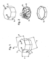
- Fig. 1 shows a perspective view of a built-in switching power supply, the is arranged in a largely closed housing 10, the Circumferential contour is designed such that it with a circular cylinder inscribed with a diameter of 55 mm and a height of about 35 mm can be.
- the housing in plan view in the form of a regular octagon, that has an edge length of about 21 mm.
- the housing consists of an upper part 12 and one Lower part 14, which are placed on top of one another and permanently connected to one another are.
- the housing 10 is largely closed and only has two through openings 16 for cable connections (in FIG. 1 only one passage opening can be seen) and passage openings 18, 20 for the introduction of fastening tools, for example one Screwdriver, on.
- Fig. 1 are not recognizable on the inside of the upper part 12 in Area of the passage openings 18 and 20 each integrally molded Guide shafts provided that guide the fastening tool to ensure.
- Guide shafts provided that guide the fastening tool to ensure.
- a single guide channel is provided.
- Fig. 2 shows an exploded view of the switching power supply of Fig. 1, wherein to can be seen that in the interior of the housing 10, a single board 22nd is arranged, which the individual electronic components and a Includes input terminal 24 and an output terminal 26.
- the housing itself consists of PA66 GV 25%, i.e. out with Glass fiber reinforced polyamide. This results in internal temperatures in continuous operation of 130 ° C possible without any problems.
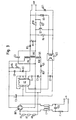
- Fig. 3 shows the electronic circuit of that shown in Figs. 1 and 2
- Built-in switching power supply based on the principle of the "flyback converter” is constructed and works according to the flyback converter principle, i.e. the performance becomes the output in the blocking phase of a MOS-FET switch transfer.
- the MOS-FET When the MOS-FET is switched on, the energy is in one Ferrite transformer stored in order to then when the MOS-FET is blocked to be returned to the exit.
- the time delay the transmission is due to the appropriate polarity of the windings and the waveform of the current in the circuit.
- the waveform the current is possible through the use of the MOS-FET transistor, which is integrated in the circuit of the off-line switcher.
- the main task of the off-line switcher is to: Closing time depending on the voltage, power grid and load of the transformer vary to get a constant output voltage.
- a capacitor C6 parallel to the input terminals, which is connected in parallel with a coil L1 as a line filter.
- a fine fuse F1 is also provided in the feed line, which only then takes effect when the electronics of the switching power supply damage suffered.
- a bridge rectifier is connected to the output of coil L1 BR1 on, the output of which is connected to connection 2 a control and switching unit U1 and on the other hand with a primary winding a transformer TR1 is connected.
- the transformer TR 1 has an auxiliary winding AUX that is proportional to the output voltage provides a retraction signal. This signal is from the control and Switching unit U1 received in the primary circuit of the transformer.
- OC1 is an optocoupler referred to, the galvanically isolated a feedback signal from the secondary side forwards to the control and switching unit U1.
Landscapes
- Engineering & Computer Science (AREA)
- Power Engineering (AREA)
- Dc-Dc Converters (AREA)
Claims (8)
- Alimentation à découpage intégrée pour la mise à disposition d'une tension continue stabilisée comprenant :une tension d'entrée d'environ 90 à 260 V ;une tension de sortie maximale d'environ 50 V ; etune puissance maximale d'environ 15 W, les composants électroniques de l'alimentation à découpage étant agencés dans un boítier (10) en grande partie fermé, dont le contour périphérique est réalisé de manière à pouvoir s'inscrire dans un cylindre droit d'un diamètre de 55 mm et d'une hauteur d'environ 35 mm.
- Alimentation à découpage selon la revendication 1, caractérisée en ce que le boítier (10) présente en vue de dessus la forme d'un octogone régulier qui possède en particulier une longueur de côté d'environ 21 mm.
- Alimentation à découpage selon la revendication 1, caractérisée en ce que le boítier (10) est réalisé en deux parties, les deux parties (12, 14) étant reliées l'une à l'autre de manière non détachable, en particulier par soudage aux ultrasons.
- Alimentation à découpage selon la revendication 1, caractérisée en ce que le boítier (10) se compose de matière plastique renforcée par des fibres de verre.
- Alimentation à découpage selon la revendication 1, caractérisée en ce que le boítier (10) est fermé, à l'exception d'orifices de passage (16, 18, 20) pour les câbles et leurs outils de fixation.
- Alimentation à découpage selon la revendication 1, caractérisée en ce que celle-ci présente un transformateur miniature (TR1) dont le bobinage secondaire (SEC) est enroulé avec un fil qui est muni de trois couches d'isolation agencées l'une sur l'autre, le fil, y compris l'isolation, présentant de préférence un diamètre d'environ 0,4 mm.
- Alimentation à découpage selon la revendication 1, caractérisée en ce que seulement un transformateur (TR1), un optocoupleur (OC1) et un condensateur de couplage (C3) sont agencés à l'emplacement de séparation entre le côté primaire et le côté secondaire.
- Alimentation à découpage selon la revendication 1, caractérisée en ce qu'un transistor MOS-FET est prévu comme élément de commutation (U1).
Applications Claiming Priority (2)
| Application Number | Priority Date | Filing Date | Title |
|---|---|---|---|
| DE10109181A DE10109181A1 (de) | 2001-02-26 | 2001-02-26 | Schaltnetzteil |
| DE10109181 | 2001-02-26 |
Publications (3)
| Publication Number | Publication Date |
|---|---|
| EP1237269A2 EP1237269A2 (fr) | 2002-09-04 |
| EP1237269A3 EP1237269A3 (fr) | 2002-11-27 |
| EP1237269B1 true EP1237269B1 (fr) | 2004-01-28 |
Family
ID=7675512
Family Applications (1)
| Application Number | Title | Priority Date | Filing Date |
|---|---|---|---|
| EP02002778A Expired - Lifetime EP1237269B1 (fr) | 2001-02-26 | 2002-02-07 | Alimentation à découpage |
Country Status (3)
| Country | Link |
|---|---|
| EP (1) | EP1237269B1 (fr) |
| DE (2) | DE10109181A1 (fr) |
| ES (1) | ES2211834T3 (fr) |
Families Citing this family (2)
| Publication number | Priority date | Publication date | Assignee | Title |
|---|---|---|---|---|
| DE202005018566U1 (de) * | 2005-11-25 | 2007-03-29 | Gira Giersiepen Gmbh & Co. Kg | Elektrisches Gerät mit Batteriefach |
| ES2728090T3 (es) * | 2015-07-27 | 2019-10-22 | Comatec Consulting S R L | Fuente de alimentación con borne de conexión a palanca pivotante |
Family Cites Families (5)
| Publication number | Priority date | Publication date | Assignee | Title |
|---|---|---|---|---|
| ES1034257Y (es) * | 1996-05-28 | 1997-05-01 | Daisalux Sa | Luminaria de emergencia perfeccionada. |
| US6176594B1 (en) * | 1998-06-09 | 2001-01-23 | Herbert Lagin | Streamlined fluorescent lamp ballast and mounting assembly |
| DE19839749C2 (de) * | 1998-09-01 | 2002-01-10 | Wilfried Poellet | Niederspannungs-Netzgerät |
| DE20009633U1 (de) * | 2000-05-29 | 2000-09-21 | Insta Elektro GmbH & Co KG, 58511 Lüdenscheid | Universelle LED-Lampe für Innen- und Außenleuchten im Netzbetrieb |
| DE20021735U1 (de) * | 2000-12-21 | 2001-02-22 | Wilhelm Koch GmbH, 33378 Rheda-Wiedenbrück | Elektronischer Transformator insbesondere für Einbauleuchten |
-
2001
- 2001-02-26 DE DE10109181A patent/DE10109181A1/de not_active Withdrawn
-
2002
- 2002-02-07 EP EP02002778A patent/EP1237269B1/fr not_active Expired - Lifetime
- 2002-02-07 DE DE50200221T patent/DE50200221D1/de not_active Expired - Lifetime
- 2002-02-07 ES ES02002778T patent/ES2211834T3/es not_active Expired - Lifetime
Also Published As
| Publication number | Publication date |
|---|---|
| EP1237269A3 (fr) | 2002-11-27 |
| EP1237269A2 (fr) | 2002-09-04 |
| DE10109181A1 (de) | 2002-09-05 |
| DE50200221D1 (de) | 2004-03-04 |
| ES2211834T3 (es) | 2004-07-16 |
Similar Documents
| Publication | Publication Date | Title |
|---|---|---|
| DE3914799A1 (de) | Durchflusswandler | |
| DE4116871A1 (de) | Ac/dc-mikrowellenofen | |
| DE3100419C2 (de) | Übertrager hoher Leistungsdichte | |
| DE20110841U1 (de) | Elektromotorischer Stelltrieb | |
| EP1237269B1 (fr) | Alimentation à découpage | |
| DE9320893U1 (de) | Netzstecker mit in diesem eingebauten Netzgerät | |
| EP4567845A1 (fr) | Système d'équipement d'installation de bâtiment | |
| EP1867035A1 (fr) | Procede de fonctionnement d'une alimentation a decoupage avec recuperation d'energie de diffusion cote primaire | |
| DE3508267A1 (de) | Ablenk-netzteil-konzept fuer fersehgeraete | |
| DE102011052449A1 (de) | Stromwandler sowie Lasttrenner mit einem solchen | |
| DE4128339C2 (de) | Leistungssteller für die Leistungssteuerung von Verbrauchern | |
| DE69310424T2 (de) | Verbindungsblock für Mittelspannungsrelais mit Stromsensoren | |
| DE102004008961B4 (de) | Spulenkörper für geschlossenen magnetischen Kern und daraus hergestellte Entstördrossel | |
| EP1847009A1 (fr) | Partie de reseau de distribution a alimentation de dispositifs independante du mode de fonctionnement de la partie d'alimentation | |
| DE60307034T2 (de) | Schaltungsanordnung zur Steuerung eines Triacs ohne galvanische Trennung | |
| EP1043805A2 (fr) | Borne à connexion électrique | |
| CH625909A5 (en) | Electrical AC switch, especially for domestic installations | |
| EP1569250A2 (fr) | Transformateur de courant et ensemble comprenant un appareil électrique | |
| DE4120147A1 (de) | Schaltregler | |
| DE3026466C2 (de) | Horizontalablenkschaltung für Fernsehempfänger | |
| DE10218455A1 (de) | Sperrwandleranordnung | |
| DE9105173U1 (de) | Busmehrfachleitung | |
| DE19915458C1 (de) | Vorrichtung zum Netzfreischalten einer elektrischen Versorgungsleitung | |
| EP1235337A2 (fr) | Circuit pour convertir courant alternatif en courant continu | |
| DE102015103296B4 (de) | Messvorrichtung zum Bereitstellen eines normierten elektrischen Ausgangssignals und elektronischer Messumformer |
Legal Events
| Date | Code | Title | Description |
|---|---|---|---|
| PUAI | Public reference made under article 153(3) epc to a published international application that has entered the european phase |
Free format text: ORIGINAL CODE: 0009012 |
|
| AK | Designated contracting states |
Kind code of ref document: A2 Designated state(s): AT BE CH CY DE DK ES FI FR GB GR IE IT LI LU MC NL PT SE TR |
|
| AX | Request for extension of the european patent |
Free format text: AL;LT;LV;MK;RO;SI |
|
| PUAL | Search report despatched |
Free format text: ORIGINAL CODE: 0009013 |
|
| RIC1 | Information provided on ipc code assigned before grant |
Free format text: 7H 02M 3/335 A, 7F 21V 21/02 B, 7F 21V 21/04 B, 7H 02M 1/00 B |
|
| AK | Designated contracting states |
Kind code of ref document: A3 Designated state(s): AT BE CH CY DE DK ES FI FR GB GR IE IT LI LU MC NL PT SE TR |
|
| AX | Request for extension of the european patent |
Free format text: AL;LT;LV;MK;RO;SI |
|
| 17P | Request for examination filed |
Effective date: 20030121 |
|
| GRAP | Despatch of communication of intention to grant a patent |
Free format text: ORIGINAL CODE: EPIDOSNIGR1 |
|
| AKX | Designation fees paid |
Designated state(s): CH DE ES FR GB IT LI |
|
| GRAS | Grant fee paid |
Free format text: ORIGINAL CODE: EPIDOSNIGR3 |
|
| GRAA | (expected) grant |
Free format text: ORIGINAL CODE: 0009210 |
|
| AK | Designated contracting states |
Kind code of ref document: B1 Designated state(s): CH DE ES FR GB IT LI |
|
| REG | Reference to a national code |
Ref country code: GB Ref legal event code: FG4D Free format text: NOT ENGLISH |
|
| REG | Reference to a national code |
Ref country code: CH Ref legal event code: EP |
|
| REG | Reference to a national code |
Ref country code: IE Ref legal event code: FG4D Free format text: GERMAN |
|
| REF | Corresponds to: |
Ref document number: 50200221 Country of ref document: DE Date of ref document: 20040304 Kind code of ref document: P |
|
| GBT | Gb: translation of ep patent filed (gb section 77(6)(a)/1977) |
Effective date: 20040216 |
|
| REG | Reference to a national code |
Ref country code: ES Ref legal event code: FG2A Ref document number: 2211834 Country of ref document: ES Kind code of ref document: T3 |
|
| REG | Reference to a national code |
Ref country code: IE Ref legal event code: FD4D |
|
| ET | Fr: translation filed | ||
| PLBE | No opposition filed within time limit |
Free format text: ORIGINAL CODE: 0009261 |
|
| STAA | Information on the status of an ep patent application or granted ep patent |
Free format text: STATUS: NO OPPOSITION FILED WITHIN TIME LIMIT |
|
| 26N | No opposition filed |
Effective date: 20041029 |
|
| PGFP | Annual fee paid to national office [announced via postgrant information from national office to epo] |
Ref country code: GB Payment date: 20120830 Year of fee payment: 11 |
|
| PGFP | Annual fee paid to national office [announced via postgrant information from national office to epo] |
Ref country code: IT Payment date: 20120830 Year of fee payment: 11 Ref country code: ES Payment date: 20120830 Year of fee payment: 11 Ref country code: FR Payment date: 20121002 Year of fee payment: 11 |
|
| GBPC | Gb: european patent ceased through non-payment of renewal fee |
Effective date: 20130207 |
|
| REG | Reference to a national code |
Ref country code: FR Ref legal event code: ST Effective date: 20131031 |
|
| PG25 | Lapsed in a contracting state [announced via postgrant information from national office to epo] |
Ref country code: IT Free format text: LAPSE BECAUSE OF NON-PAYMENT OF DUE FEES Effective date: 20130207 |
|
| PG25 | Lapsed in a contracting state [announced via postgrant information from national office to epo] |
Ref country code: FR Free format text: LAPSE BECAUSE OF NON-PAYMENT OF DUE FEES Effective date: 20130228 Ref country code: GB Free format text: LAPSE BECAUSE OF NON-PAYMENT OF DUE FEES Effective date: 20130207 |
|
| REG | Reference to a national code |
Ref country code: ES Ref legal event code: FD2A Effective date: 20140408 |
|
| PG25 | Lapsed in a contracting state [announced via postgrant information from national office to epo] |
Ref country code: ES Free format text: LAPSE BECAUSE OF NON-PAYMENT OF DUE FEES Effective date: 20130208 |
|
| PGFP | Annual fee paid to national office [announced via postgrant information from national office to epo] |
Ref country code: CH Payment date: 20190218 Year of fee payment: 18 |
|
| REG | Reference to a national code |
Ref country code: CH Ref legal event code: PL |
|
| PG25 | Lapsed in a contracting state [announced via postgrant information from national office to epo] |
Ref country code: LI Free format text: LAPSE BECAUSE OF NON-PAYMENT OF DUE FEES Effective date: 20200229 Ref country code: CH Free format text: LAPSE BECAUSE OF NON-PAYMENT OF DUE FEES Effective date: 20200229 |
|
| PGFP | Annual fee paid to national office [announced via postgrant information from national office to epo] |
Ref country code: DE Payment date: 20210428 Year of fee payment: 20 |