EP1237269B1 - Switched mode power supply - Google Patents
Switched mode power supply Download PDFInfo
- Publication number
- EP1237269B1 EP1237269B1 EP02002778A EP02002778A EP1237269B1 EP 1237269 B1 EP1237269 B1 EP 1237269B1 EP 02002778 A EP02002778 A EP 02002778A EP 02002778 A EP02002778 A EP 02002778A EP 1237269 B1 EP1237269 B1 EP 1237269B1
- Authority
- EP
- European Patent Office
- Prior art keywords
- power supply
- supply unit
- housing
- accordance
- approximately
- Prior art date
- Legal status (The legal status is an assumption and is not a legal conclusion. Google has not performed a legal analysis and makes no representation as to the accuracy of the status listed.)
- Expired - Lifetime
Links
- 238000004804 winding Methods 0.000 claims description 5
- 239000003990 capacitor Substances 0.000 claims description 4
- 238000009413 insulation Methods 0.000 claims description 3
- 238000000926 separation method Methods 0.000 claims description 3
- 238000003466 welding Methods 0.000 claims description 3
- 230000008878 coupling Effects 0.000 claims description 2
- 238000010168 coupling process Methods 0.000 claims description 2
- 238000005859 coupling reaction Methods 0.000 claims description 2
- 239000003365 glass fiber Substances 0.000 claims description 2
- 230000002093 peripheral effect Effects 0.000 claims description 2
- 229920002430 Fibre-reinforced plastic Polymers 0.000 claims 1
- 230000005693 optoelectronics Effects 0.000 claims 1
- 238000009434 installation Methods 0.000 description 3
- 230000005540 biological transmission Effects 0.000 description 2
- 238000004382 potting Methods 0.000 description 2
- WCFLPIUONATZLJ-UHFFFAOYSA-N C1CC#SCC1 Chemical compound C1CC#SCC1 WCFLPIUONATZLJ-UHFFFAOYSA-N 0.000 description 1
- 239000004952 Polyamide Substances 0.000 description 1
- 238000004026 adhesive bonding Methods 0.000 description 1
- 230000000903 blocking effect Effects 0.000 description 1
- 230000000052 comparative effect Effects 0.000 description 1
- 150000001875 compounds Chemical class 0.000 description 1
- 238000010586 diagram Methods 0.000 description 1
- 230000000694 effects Effects 0.000 description 1
- 239000011152 fibreglass Substances 0.000 description 1
- 229920002647 polyamide Polymers 0.000 description 1
- 230000009993 protective function Effects 0.000 description 1
- 239000000779 smoke Substances 0.000 description 1
- 229910000859 α-Fe Inorganic materials 0.000 description 1
Images
Classifications
-
- H—ELECTRICITY
- H02—GENERATION; CONVERSION OR DISTRIBUTION OF ELECTRIC POWER
- H02M—APPARATUS FOR CONVERSION BETWEEN AC AND AC, BETWEEN AC AND DC, OR BETWEEN DC AND DC, AND FOR USE WITH MAINS OR SIMILAR POWER SUPPLY SYSTEMS; CONVERSION OF DC OR AC INPUT POWER INTO SURGE OUTPUT POWER; CONTROL OR REGULATION THEREOF
- H02M1/00—Details of apparatus for conversion
- H02M1/32—Means for protecting converters other than automatic disconnection
Definitions
- the present invention relates to a switching power supply a stabilized DC voltage and in particular a stabilized one Micro power supply for electrical and electronic devices.
- Switching power supplies and in particular built-in switching power supplies are fundamental known and serve to stabilize DC voltage from a Derive mains voltage, for example to supply sensors.
- the switching power supply according to the invention is characterized in that on the one hand there is a comparatively high power limit of around 15 W, on the other hand, the outer dimensions of the switching power supply very are low.
- the outer contour of the housing is chosen so that certain Maximum dimensions are not exceeded. This brings the big one Advantage with it that the switching power supply according to the invention including its housing can be used in any standard flush-mounted box can.
- the housing can be in Top view have the shape of a regular octagon, which in particular has an edge length of about 21 mm.
- octagonal shape is the installation of the switching power supply in a commercially available Switch box relieved, the octagonal shape an extreme easy access to the input and output terminals allowed.
- the housing be formed in two parts, the two parts in particular by Ultrasonic welding or permanently bonded together by gluing could be.
- Such a two-part design of the housing offers one easy installation and good protection of the arranged inside the housing electronic components without the need for the interior of the housing to shed with a potting compound.
- the housing can preferably be made of glass fiber reinforced plastic, which one temperature-resistant continuous operation. Even with a longer one continuous overload operation ensures that the housing takes over its protective function.
- the switching power supply has one Miniature transformer on whose secondary winding with a wire is wound, with three insulation layers arranged one above the other is provided.
- the wire may preferably have a diameter of approximately 0.4 mm.
- a switching and control circuit is preferably used for the switching power supply, which works on the flyback principle and an integrated MOS-FET, which acts as a switch element.
- the control unit can switch the MOS-FET with a frequency of 50 to 500 kHz and so that the output current and the output voltage are independent of Control fluctuations in the input voltage.
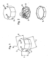
- Fig. 1 shows a perspective view of a built-in switching power supply, the is arranged in a largely closed housing 10, the Circumferential contour is designed such that it with a circular cylinder inscribed with a diameter of 55 mm and a height of about 35 mm can be.
- the housing in plan view in the form of a regular octagon, that has an edge length of about 21 mm.
- the housing consists of an upper part 12 and one Lower part 14, which are placed on top of one another and permanently connected to one another are.
- the housing 10 is largely closed and only has two through openings 16 for cable connections (in FIG. 1 only one passage opening can be seen) and passage openings 18, 20 for the introduction of fastening tools, for example one Screwdriver, on.
- Fig. 1 are not recognizable on the inside of the upper part 12 in Area of the passage openings 18 and 20 each integrally molded Guide shafts provided that guide the fastening tool to ensure.
- Guide shafts provided that guide the fastening tool to ensure.
- a single guide channel is provided.
- Fig. 2 shows an exploded view of the switching power supply of Fig. 1, wherein to can be seen that in the interior of the housing 10, a single board 22nd is arranged, which the individual electronic components and a Includes input terminal 24 and an output terminal 26.
- the housing itself consists of PA66 GV 25%, i.e. out with Glass fiber reinforced polyamide. This results in internal temperatures in continuous operation of 130 ° C possible without any problems.
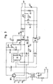
- Fig. 3 shows the electronic circuit of that shown in Figs. 1 and 2
- Built-in switching power supply based on the principle of the "flyback converter” is constructed and works according to the flyback converter principle, i.e. the performance becomes the output in the blocking phase of a MOS-FET switch transfer.
- the MOS-FET When the MOS-FET is switched on, the energy is in one Ferrite transformer stored in order to then when the MOS-FET is blocked to be returned to the exit.
- the time delay the transmission is due to the appropriate polarity of the windings and the waveform of the current in the circuit.
- the waveform the current is possible through the use of the MOS-FET transistor, which is integrated in the circuit of the off-line switcher.
- the main task of the off-line switcher is to: Closing time depending on the voltage, power grid and load of the transformer vary to get a constant output voltage.
- a capacitor C6 parallel to the input terminals, which is connected in parallel with a coil L1 as a line filter.
- a fine fuse F1 is also provided in the feed line, which only then takes effect when the electronics of the switching power supply damage suffered.
- a bridge rectifier is connected to the output of coil L1 BR1 on, the output of which is connected to connection 2 a control and switching unit U1 and on the other hand with a primary winding a transformer TR1 is connected.
- the transformer TR 1 has an auxiliary winding AUX that is proportional to the output voltage provides a retraction signal. This signal is from the control and Switching unit U1 received in the primary circuit of the transformer.
- OC1 is an optocoupler referred to, the galvanically isolated a feedback signal from the secondary side forwards to the control and switching unit U1.
Landscapes
- Engineering & Computer Science (AREA)
- Power Engineering (AREA)
- Dc-Dc Converters (AREA)
Description
Die vorliegende Erfindung betrifft ein Schaltnetzteil zur Bereitstellung einer stabilisierten Gleichspannung und insbesondere eine stabilisierte Mikro-Stromversorgung für elektrische und elektronische Geräte.The present invention relates to a switching power supply a stabilized DC voltage and in particular a stabilized one Micro power supply for electrical and electronic devices.
Schaltnetzteile und insbesondere Einbau-Schaltnetzteile sind grundsätzlich bekannt und dienen dazu, eine stabilisierte Gleichspannung aus einer Netzspannung abzuleiten, um beispielsweise Meßwertgeber zu versorgen.Switching power supplies and in particular built-in switching power supplies are fundamental known and serve to stabilize DC voltage from a Derive mains voltage, for example to supply sensors.
Insbesondere wenn beispielsweise Kleinkameras, Alarmsensoren, Rauchmelder, Rollladen-, Jalousien oder Dachfensterantriebe mit Niederspannung versorgt werden müssen, mußte bislang eine zusätzliche Leitung gelegt werden, die - falls sie in den gleichen Kabelkanal der Hauptleitung gelegt wird - den gleichen Isolationsgrad wie die Hauptleitung aufweisen muß. Alternativ kann eine Standardstromversorgung zum Einbau oder zur Wandmontage in der Nähe des zu versorgenden Gerätes montiert werden oder es muß ein neuer Kabelkanal für die Kabel der stabilisierten Niederspannung bis zu dem zu speisenden Gerät gelegt werden.Especially if, for example, small cameras, alarm sensors, smoke detectors, Roller shutters, blinds or roof window drives with low voltage So far, an additional line had to be supplied which - if they are in the same cable duct of the main line is laid - have the same degree of insulation as the main line got to. Alternatively, a standard power supply for installation or mounted for wall mounting near the device to be supplied or there must be a new cable channel for the cables of the stabilized Low voltage down to the device to be fed.
Das Einführen mehrerer Kabel in einen Kabelkanal kann zu Platzproblemen im Kabelkanal führen und es kann insbesondere beim späteren Einführen von Kabeln in einen schon gelegten Kabelkanal zu unüberwindbaren Problemen kommen. Hinzu kommt, daß die Stromversorgungen der herkömmlichen Art verhältnismäßig groß sind, einen niedrigen Wirkungsgrad, jedoch eine hohe Temperaturabgabe aufweisen. Inserting several cables into one cable duct can cause space problems lead in the cable duct and it can be especially in the later Introducing cables into an already insurmountable cable duct Problems come up. Add to that the power supplies the conventional type are relatively large, a low one Efficiency, but have a high temperature output.
Es ist die Aufgabe der Erfindung, ein Einbau-Schaltnetzteil zur Verfügung zu stellen, das die o.g. Probleme beseitigt und dennoch eine vergleichsweise hohe Leistung aufweist.It is the object of the invention to provide a built-in switching power supply that the above-mentioned Problems solved and still a comparative one has high performance.
Die Lösung dieser Aufgabe erfolgt durch die Merkmale des Anspruchs 1
und insbesondere durch ein Einbau-Schaltnetzteil mit einer Eingangsspannung
von etwa 90 bis 260 V (Wechselspannung), einer maximalen
Ausgangsspannung von etwa 50 V (Gleichspannung) und einer maximalen
Leistung von etwa 15 W, wobei die elektronischen Bauteile des Schaltnetzteiles
in einem weitgehend geschlossenen Gehäuse angeordnet sind,
dessen Umfangskontur derart gestaltet ist, daß es in einen Kreiszylinder
mit einem Durchmesser von 55 mm und einer Höhe von etwa 35 mm
einbeschrieben werden kann.This object is achieved by the features of
Das erfindungsgemäße Schaltnetzteil zeichnet sich dadurch aus, daß einerseits eine vergleichsweise hohe Leistungsgrenze von etwa 15 W vorliegt, wobei andererseits die Außenabmessungen des Schaltnetzteiles sehr gering sind. Die Außenkontur des Gehäuses ist so gewählt, daß bestimmte Maximalabmessungen nicht überschritten werden. Dies bringt den großen Vorteil mit sich, daß das erfindungsgemäße Schaltnetzteil einschließlich seines Gehäuses in jeder handelsüblichen Unterputzdose eingesetzt werden kann.The switching power supply according to the invention is characterized in that on the one hand there is a comparatively high power limit of around 15 W, on the other hand, the outer dimensions of the switching power supply very are low. The outer contour of the housing is chosen so that certain Maximum dimensions are not exceeded. This brings the big one Advantage with it that the switching power supply according to the invention including its housing can be used in any standard flush-mounted box can.
Vorteilhafte Ausführungsformen der Erfindung sind in der Beschreibung, der Zeichnung, sowie den Unteransprüchen beschrieben.Advantageous embodiments of the invention are in the description, the drawing and the subclaims.
Nach einer ersten vorteilhaften Ausführungsform kann das Gehäuse in Draufsicht die Form eines regelmäßigen Achtecks aufweisen, das insbesondere eine Kantenlänge von etwa 21 mm besitzt. Durch eine solche achteckige Form ist der Einbau des Schaltnetzteiles in eine handelsübliche Schalterdose erleichtert, wobei die achteckige Form einen äußerst leichten Zugang zu den Eingangs- bzw. Ausgangsklemmen erlaubt.According to a first advantageous embodiment, the housing can be in Top view have the shape of a regular octagon, which in particular has an edge length of about 21 mm. By such octagonal shape is the installation of the switching power supply in a commercially available Switch box relieved, the octagonal shape an extreme easy access to the input and output terminals allowed.
Nach einer weiteren vorteilhaften Ausführungsform kann das Gehäuse zweiteilig ausgebildet sein, wobei die beiden Teile insbesondere durch Ultraschallschweißen oder durch Kleben unlösbar miteinander verbunden sein können. Eine solche zweiteilige Ausbildung des Gehäuses bietet eine einfache Montage und einen guten Schutz der im Gehäuseinneren angeordneten elektronischen Bauteile, ohne daß es erforderlich ist, das Gehäuseinnere mit einer Vergußmasse zu vergießen. Das Gehäuse kann bevorzugt aus glasfaserverstärktem Kunststoff hergestellt sein, was einen temperaturbeständigen Dauerbetrieb ermöglicht. Auch bei einem länger andauernden Überlastbetrieb ist hierbei sichergestellt, daß das Gehäuse seine Schutzfunktion übernimmt.According to a further advantageous embodiment, the housing be formed in two parts, the two parts in particular by Ultrasonic welding or permanently bonded together by gluing could be. Such a two-part design of the housing offers one easy installation and good protection of the arranged inside the housing electronic components without the need for the interior of the housing to shed with a potting compound. The housing can preferably be made of glass fiber reinforced plastic, which one temperature-resistant continuous operation. Even with a longer one continuous overload operation ensures that the housing takes over its protective function.
Es ist vorteilhaft, wenn das Gehäuse mit Ausnahme von Durchtrittsöffnungen für Kabel und deren Befestigungswerkzeuge geschlossen ist, da in diesem Fall kein unerwünschter Zugriff auf spannungsführende Teile möglich ist.It is advantageous if the housing with the exception of passage openings for cables and their fastening tools is closed because in in this case no unwanted access to live parts is possible.
Nach einer bevorzugten Ausführungsform weist das Schaltnetzteil einen Miniaturtransformator auf, dessen Sekundärwicklung mit einem Draht gewickelt ist, der mit drei übereinander angeordneten Isolationsschichten versehen ist. Der Draht kann vorzugsweise einen Durchmesser von etwa 0,4 mm aufweisen. Durch die Verwendung eines solchen dreifach isolierten Drahtes auf der Sekundärseite kann eine optimale Ausnutzung des Wickelraumes erreicht werden, wobei dennoch die von den Sicherheitsnormen vorgegebenen Luft- und Kriechstrecken eingehalten werden können. Gleichzeitig läßt sich ein relativ hoher Leistungsbereich bis etwa 15 W abdecken.According to a preferred embodiment, the switching power supply has one Miniature transformer on whose secondary winding with a wire is wound, with three insulation layers arranged one above the other is provided. The wire may preferably have a diameter of approximately 0.4 mm. By using such a triple insulated Wire on the secondary side can be used optimally Changing room can be achieved, but still by the safety standards specified air and creepage distances can be maintained. At the same time, a relatively high performance range of up to approximately Cover 15 W.
Aufgrund der sehr kleinen Abmessungen ist grundsätzlich die galvanische Trennung zwischen Primärseite und Sekundärseite problematisch. Erfindungsgemäß sind jedoch an der Trennstelle zwischen Primärseite und Sekundärseite lediglich ein Transformator, ein Optokoppler und ein Koppelkondensator vorgesehen, so daß die erforderlichen Luft- und Kriechstrecken trotz der sehr geringen Abmessungen und ohne Vergießen der elektronischen Bauteile eingehalten werden können.Because of the very small dimensions, it is basically galvanic Separation between primary and secondary side problematic. According to the invention are however at the separation point between primary side and Secondary side only a transformer, an optocoupler and a coupling capacitor provided so that the required clearance and creepage distances despite the very small dimensions and without potting the electronic components can be maintained.
Bevorzugt wird für das Schaltnetzteil ein Schalt- und Regelkreis verwendet, der nach dem Sperrwandler-Prinzip arbeitet und einen integrierten MOS-FET aufweist, der als Schalterelement fungiert. Die Kontrolleinheit kann den MOS-FET mit einer Frequenz von 50 bis 500 kHz schalten und damit den Ausgangsstrom und die Ausgangsspannung unabhängig von Schwankungen der Eingangsspannung regeln.A switching and control circuit is preferably used for the switching power supply, which works on the flyback principle and an integrated MOS-FET, which acts as a switch element. The control unit can switch the MOS-FET with a frequency of 50 to 500 kHz and so that the output current and the output voltage are independent of Control fluctuations in the input voltage.
Nachfolgend wird die vorliegende Erfindung rein beispielhaft anhand einer vorteilhaften Ausführungsform und unter Bezugnahme auf die beigefügten Zeichnungen beschrieben. Es zeigen:
- Fig. 1
- eine perspektivische Ansicht des Einbau-Schaltnetzteils bei geschlossenem Gehäuse;
- Fig. 2
- eine Explosionsdarstellung des Schaltnetzteils von Fig. 1; und
- Fig. 3
- den Schaltplan des Schaltnetzteils von Fig. 1 und 2.
- Fig. 1
- a perspective view of the built-in switching power supply with the housing closed;
- Fig. 2
- an exploded view of the switching power supply of Fig. 1; and
- Fig. 3
- the circuit diagram of the switching power supply of Fig. 1 and 2.
Fig. 1 zeigt eine perspektivische Ansicht eines Einbau-Schaltnetzteils, das
in einem weitgehend geschlossenen Gehäuse 10 angeordnet ist, dessen
Umfangskontur derart gestaltet ist, daß es in einen Kreiszylinder mit
einem Durchmesser von 55 mm und einer Höhe von etwa 35 mm einbeschrieben
werden kann. Bei dem dargestellten Ausführungsbeispiel ist
das Gehäuse in Draufsicht in Form eines regelmäßigen Achtecks ausgebildet,
das eine Kantenlänge von etwa 21 mm besitzt. Die in Fig. 1 dargestellten
Maße betragen A = 50,81 mm, B = 55 mm und C = 32 mm.Fig. 1 shows a perspective view of a built-in switching power supply, the
is arranged in a largely closed
Wie Fig. 1 zeigt, besteht das Gehäuse aus einem Oberteil 12 und einem
Unterteil 14, die aufeinander aufgesetzt und miteinander unlösbar verbunden
sind. Das Gehäuse 10 ist weitgehend geschlossen angeordnet und
weist lediglich zwei Durchtrittsöffnungen 16 für Kabelanschlüsse (in Fig. 1
ist nur eine Durchtrittsöffnung zu sehen) sowie Durchtrittsöffnungen 18,
20 für die Einführung von Befestigungswerkzeugen, beispielsweise einem
Schraubendreher, auf.1 shows, the housing consists of an
In Fig. 1 nicht erkennbar sind an der Innenseite des Oberteils 12 im
Bereich der Durchtrittsöffnungen 18 und 20 jeweils einstückig angeformte
Führungsschächte vorgesehen, die eine Führung des Befestigungswerkzeuges
sicherstellen. Hierbei sind für die beabstandet ausgebildeten
Durchtrittsöffnungen 18 zwei separate und voneinander isolierte Führungskanäle
vorgesehen, wohingegen für die aneinander angrenzenden
Durchtrittsöffnungen 20 ein einziger Führungskanal vorgesehen ist.In Fig. 1 are not recognizable on the inside of the
Fig. 2 zeigt eine Explosionsansicht des Schaltnetzteils von Fig. 1, wobei zu
erkennen ist, daß im Inneren des Gehäuses 10 eine einzige Platine 22
angeordnet ist, welche die einzelnen elektronischen Bauteile sowie eine
Eingangsklemme 24 und eine Ausgangsklemme 26 enthält. Fig. 2 shows an exploded view of the switching power supply of Fig. 1, wherein to
can be seen that in the interior of the
Bei der Montage wird lediglich die vollständig bestückte Platine 22 in das
Unterteil 14 des Gehäuses 10 eingesetzt. Anschließend wird das Oberteil
12 auf das Unterteil 14 aufgesetzt und mittels Ultraschallschweißens
verschweißt. Das Gehäuse selbst besteht aus PA66 GV 25 %, d.h. aus mit
Glasfaser verstärktem Polyamid. Hierdurch sind im Dauerbetrieb Innentemperaturen
von 130°C problemlos möglich.During assembly, only the fully assembled board 22 is in the
Fig. 3 zeigt die elektronische Schaltung des in den Fig. 1 und 2 dargestellten Einbau-Schaltnetzteils, das nach dem Prinzip des "flyback converter" aufgebaut ist und nach dem Sperrwandler-Prinzip arbeitet, d.h. die Leistung wird in der Sperrphase eines MOS-FET-Schalters zum Ausgang übertragen. Bei eingeschaltetem MOS-FET wird die Energie in einem Ferrit-Transformator gespeichert, um dann bei gesperrtem MOS-FET wieder an den Ausgang abgegeben zu werden. Die zeitliche Verzögerung der Übertragung wird durch die angemessene Polarität der Wicklungen und der Wellenform des Stroms im Kreislauf hervorgerufen. Die Wellenform des Stroms ist durch den Einsatz des MOS-FET-Transistors möglich, der im Schaltkreis des off-line switchers integriert ist. Dieser wird durch eine logische Kontrolleinheit gesteuert, die den MOS-FET mit einer Frequenz von 50 bis 500 kHz schaltet und dadurch den Ausgangsstrom und die Ausgangsspannung unabhängig von Schwankungen der Eingangsspannung regelt. Die Hauptaufgabe des off-line switchers liegt darin, die Schließzeit je nach Spannung, Stromnetz und Last des Transformators zu variieren, um eine konstante Ausgangsspannung zu erhalten.Fig. 3 shows the electronic circuit of that shown in Figs. 1 and 2 Built-in switching power supply based on the principle of the "flyback converter" is constructed and works according to the flyback converter principle, i.e. the performance becomes the output in the blocking phase of a MOS-FET switch transfer. When the MOS-FET is switched on, the energy is in one Ferrite transformer stored in order to then when the MOS-FET is blocked to be returned to the exit. The time delay the transmission is due to the appropriate polarity of the windings and the waveform of the current in the circuit. The waveform the current is possible through the use of the MOS-FET transistor, which is integrated in the circuit of the off-line switcher. This is through a logic control unit that controls the MOS-FET at a frequency switches from 50 to 500 kHz and thereby the output current and the output voltage regardless of fluctuations in the input voltage regulates. The main task of the off-line switcher is to: Closing time depending on the voltage, power grid and load of the transformer vary to get a constant output voltage.
Wie Fig. 3 zeigt, befindet sich ausgehend von den mit "In" bezeichneten
Eingangsklemmen zunächst ein Kondensator C6 parallel zu den Eingangsklemmen,
der mit einer Spule L1 als Netzfilter parallelgeschaltet ist.
In der Zuleitung ist ferner eine Feinsicherung F1 vorgesehen, die nur
dann wirksam wird, wenn die Elektronik des Schaltnetzteils einen Schaden
erlitten hat. An den Ausgang der Spule L1 schließt sich ein Brückengleichrichter
BR1 an, dessen Ausgang einerseits mit dem Anschluß 2
einer Kontroll- und Schalteinheit U1 und andererseits mit einer Primärwicklung
eines Transformators TR1 verbunden ist. Der Transformator TR 1
weist eine Hilfswicklung AUX auf, die proportional zur Ausgangsspannung
ein Retruaktions-Signal liefert. Dieses Signal wird von der Kontroll- und
Schalteinheit U1 im Primärschaltkreis des Transformators empfangen.
Hierdurch kann die vom Eingang zum Ausgang des Schaltnetzteils übertragene
Energie des Transformators kontrolliert werden und die Ausgangsspannung
kann bei wechselnder Eingangsspannung und wechselndem
Ausgangsstrom gleichgehalten werden. Mit OC1 ist ein Optokoppler
bezeichnet, der galvanisch getrennt ein Rückkoppelsignal von der Sekundärseite
an die Kontroll- und Schalteinheit U1 weiterleitet. As shown in FIG. 3, starting from those labeled "In"
Input terminals first a capacitor C6 parallel to the input terminals,
which is connected in parallel with a coil L1 as a line filter.
A fine fuse F1 is also provided in the feed line, which only
then takes effect when the electronics of the switching power supply damage
suffered. A bridge rectifier is connected to the output of coil L1
BR1 on, the output of which is connected to connection 2
a control and switching unit U1 and on the other hand with a primary winding
a transformer TR1 is connected. The
- 1010
- Gehäusecasing
- 1212
- Oberteiltop
- 1414
- Unterteillower part
- 1616
- DurchtrittsöffnungThrough opening
- 18, 2018, 20
- DurchtrittsöffnungThrough opening
- 2222
- Platinecircuit board
- 2424
- Eingangsklemmeinput terminal
- 2626
- Ausgangsklemmeoutput terminal
- AA
- Breitewidth
- BB
- Durchmesserdiameter
- CC
- Höheheight
- BR1BR1
- GleichrichterbrückeRectifier bridge
- C1-C8C1-C8
- Kondensatorencapacitors
- D1-D3D1-D3
- Diodendiodes
- DZ1DZ1
- Zener-DiodeZener diode
- F1F1
- FeinsicherungFeinsicherung
-
L 1
L 1 - NetzfilterLine filter
- OC1OC1
- Optokoppleroptocoupler
- Q1Q1
- Transistortransistor
- R1-R10R1-R10
- Widerständeresistors
- TR1TR1
- HF-TransformatorHF transformer
- U1U1
- Kontroll- und SchalteinheitControl and switching unit
Claims (8)
- An installable power supply unit for providing a stabilised DC voltage, having
an input voltage from approximately 90 up to 260 V;
a maximum output voltage of approximately 50 V; and
a maximum power of approximately 15 W, wherein
the electronic components of the power supply unit are arranged in a largely closed housing (10) whose peripheral contour is designed such that it can be inscribed in a circular cylinder with a diameter of 55 mm and a height of approximately 35 mm. - A power supply unit in accordance with claim 1, characterized in that the housing (10) has the shape of a regular octagon in a plan view which in particular has an edge length of approximately 21 mm.
- A power supply unit in accordance with claim 1, characterized in that the housing (10) is made in two parts, with the two parts (12, 14) in particular being non-releasably connected to one another by ultrasonic welding.
- A power supply unit in accordance with claim 1, characterized in that the housing (10) consists of glass fibre reinforced plastic.
- A power supply unit in accordance with claim 1, characterized in that the housing (10) is closed with the exception of passage openings (16, 18, 20) for cables and their fastening tools.
- A power supply unit in accordance with claim 1, characterized in that it has a miniature transformer (TR1) whose secondary winding (SEC) is wound with a wire which is provided with three insulating layers arranged on top of one another, with the wire, including insulation, preferably having a diameter of approximately 0.4 mm.
- A power supply unit in accordance with claim 1, characterized in only one transformer (TR1), one optoelectronic coupler (OC1) and one coupling capacitor (C3) are arranged at the separation point between the primary side and the secondary side.
- A power supply unit in accordance with claim 1, characterized in that a MOSFET transistor is provided as the switching element (U1).
Applications Claiming Priority (2)
| Application Number | Priority Date | Filing Date | Title |
|---|---|---|---|
| DE10109181A DE10109181A1 (en) | 2001-02-26 | 2001-02-26 | Switching Power Supply |
| DE10109181 | 2001-02-26 |
Publications (3)
| Publication Number | Publication Date |
|---|---|
| EP1237269A2 EP1237269A2 (en) | 2002-09-04 |
| EP1237269A3 EP1237269A3 (en) | 2002-11-27 |
| EP1237269B1 true EP1237269B1 (en) | 2004-01-28 |
Family
ID=7675512
Family Applications (1)
| Application Number | Title | Priority Date | Filing Date |
|---|---|---|---|
| EP02002778A Expired - Lifetime EP1237269B1 (en) | 2001-02-26 | 2002-02-07 | Switched mode power supply |
Country Status (3)
| Country | Link |
|---|---|
| EP (1) | EP1237269B1 (en) |
| DE (2) | DE10109181A1 (en) |
| ES (1) | ES2211834T3 (en) |
Families Citing this family (2)
| Publication number | Priority date | Publication date | Assignee | Title |
|---|---|---|---|---|
| DE202005018566U1 (en) * | 2005-11-25 | 2007-03-29 | Gira Giersiepen Gmbh & Co. Kg | Electric device with battery compartment |
| ES2728090T3 (en) * | 2015-07-27 | 2019-10-22 | Comatec Consulting S R L | Power supply with pivot lever connection terminal |
Family Cites Families (5)
| Publication number | Priority date | Publication date | Assignee | Title |
|---|---|---|---|---|
| ES1034257Y (en) * | 1996-05-28 | 1997-05-01 | Daisalux Sa | PERFECTED EMERGENCY LIGHTING. |
| US6176594B1 (en) * | 1998-06-09 | 2001-01-23 | Herbert Lagin | Streamlined fluorescent lamp ballast and mounting assembly |
| DE19839749C2 (en) * | 1998-09-01 | 2002-01-10 | Wilfried Poellet | Low voltage power supply |
| DE20009633U1 (en) * | 2000-05-29 | 2000-09-21 | Insta Elektro GmbH & Co KG, 58511 Lüdenscheid | Universal LED lamp for indoor and outdoor lighting in mains operation |
| DE20021735U1 (en) * | 2000-12-21 | 2001-02-22 | Wilhelm Koch GmbH, 33378 Rheda-Wiedenbrück | Electronic transformer, especially for recessed lights |
-
2001
- 2001-02-26 DE DE10109181A patent/DE10109181A1/en not_active Withdrawn
-
2002
- 2002-02-07 EP EP02002778A patent/EP1237269B1/en not_active Expired - Lifetime
- 2002-02-07 DE DE50200221T patent/DE50200221D1/en not_active Expired - Lifetime
- 2002-02-07 ES ES02002778T patent/ES2211834T3/en not_active Expired - Lifetime
Also Published As
| Publication number | Publication date |
|---|---|
| EP1237269A3 (en) | 2002-11-27 |
| EP1237269A2 (en) | 2002-09-04 |
| DE10109181A1 (en) | 2002-09-05 |
| DE50200221D1 (en) | 2004-03-04 |
| ES2211834T3 (en) | 2004-07-16 |
Similar Documents
| Publication | Publication Date | Title |
|---|---|---|
| DE3914799A1 (en) | FLOW CONVERTER | |
| DE4116871A1 (en) | AC / DC MICROWAVE OVEN | |
| DE3100419C2 (en) | High power density transformer | |
| DE20110841U1 (en) | Electromotive actuator | |
| EP1237269B1 (en) | Switched mode power supply | |
| DE9320893U1 (en) | Power plug with built-in power supply | |
| EP4567845A1 (en) | Building installation equipment system | |
| EP1867035A1 (en) | Method for operating a switched mode power supply with the recovery of primary scattered energy | |
| DE3508267A1 (en) | DEFLECTION POWER SUPPLY CONCEPT FOR TELEVISION EQUIPMENT | |
| DE102011052449A1 (en) | Current transformer and load disconnector with such | |
| DE4128339C2 (en) | Power controller for the power control of consumers | |
| DE69310424T2 (en) | Connection block for medium voltage relays with current sensors | |
| DE102004008961B4 (en) | Coil body for closed magnetic core, has guiding units arranged outside supporting surface, winding space defined between units and under windings, and separating units designed as flat ledges | |
| EP1847009A1 (en) | Switched-mode power supply unit wherein devices are supplied with power independently of the operating state of the power component | |
| DE60307034T2 (en) | Circuit arrangement for controlling a triac without galvanic isolation | |
| EP1043805A2 (en) | Electrical connection terminal | |
| CH625909A5 (en) | Electrical AC switch, especially for domestic installations | |
| EP1569250A2 (en) | Current transformer and assembly with electrical device | |
| DE4120147A1 (en) | Switching regulator with push=pull resonant DC=DC converter | |
| DE3026466C2 (en) | Horizontal deflection circuit for television receivers | |
| DE10218455A1 (en) | Flyback arrangement | |
| DE9105173U1 (en) | Bus multiple line | |
| DE19915458C1 (en) | Device for mains release of one or more supply lines connects load to supply line if load switched on signal is received and separates supply line from mains if not | |
| EP1235337A2 (en) | Circuit for convertion of AC into DC | |
| DE102015103296B4 (en) | Measuring device for providing a standardized electrical output signal and electronic measuring transducer |
Legal Events
| Date | Code | Title | Description |
|---|---|---|---|
| PUAI | Public reference made under article 153(3) epc to a published international application that has entered the european phase |
Free format text: ORIGINAL CODE: 0009012 |
|
| AK | Designated contracting states |
Kind code of ref document: A2 Designated state(s): AT BE CH CY DE DK ES FI FR GB GR IE IT LI LU MC NL PT SE TR |
|
| AX | Request for extension of the european patent |
Free format text: AL;LT;LV;MK;RO;SI |
|
| PUAL | Search report despatched |
Free format text: ORIGINAL CODE: 0009013 |
|
| RIC1 | Information provided on ipc code assigned before grant |
Free format text: 7H 02M 3/335 A, 7F 21V 21/02 B, 7F 21V 21/04 B, 7H 02M 1/00 B |
|
| AK | Designated contracting states |
Kind code of ref document: A3 Designated state(s): AT BE CH CY DE DK ES FI FR GB GR IE IT LI LU MC NL PT SE TR |
|
| AX | Request for extension of the european patent |
Free format text: AL;LT;LV;MK;RO;SI |
|
| 17P | Request for examination filed |
Effective date: 20030121 |
|
| GRAP | Despatch of communication of intention to grant a patent |
Free format text: ORIGINAL CODE: EPIDOSNIGR1 |
|
| AKX | Designation fees paid |
Designated state(s): CH DE ES FR GB IT LI |
|
| GRAS | Grant fee paid |
Free format text: ORIGINAL CODE: EPIDOSNIGR3 |
|
| GRAA | (expected) grant |
Free format text: ORIGINAL CODE: 0009210 |
|
| AK | Designated contracting states |
Kind code of ref document: B1 Designated state(s): CH DE ES FR GB IT LI |
|
| REG | Reference to a national code |
Ref country code: GB Ref legal event code: FG4D Free format text: NOT ENGLISH |
|
| REG | Reference to a national code |
Ref country code: CH Ref legal event code: EP |
|
| REG | Reference to a national code |
Ref country code: IE Ref legal event code: FG4D Free format text: GERMAN |
|
| REF | Corresponds to: |
Ref document number: 50200221 Country of ref document: DE Date of ref document: 20040304 Kind code of ref document: P |
|
| GBT | Gb: translation of ep patent filed (gb section 77(6)(a)/1977) |
Effective date: 20040216 |
|
| REG | Reference to a national code |
Ref country code: ES Ref legal event code: FG2A Ref document number: 2211834 Country of ref document: ES Kind code of ref document: T3 |
|
| REG | Reference to a national code |
Ref country code: IE Ref legal event code: FD4D |
|
| ET | Fr: translation filed | ||
| PLBE | No opposition filed within time limit |
Free format text: ORIGINAL CODE: 0009261 |
|
| STAA | Information on the status of an ep patent application or granted ep patent |
Free format text: STATUS: NO OPPOSITION FILED WITHIN TIME LIMIT |
|
| 26N | No opposition filed |
Effective date: 20041029 |
|
| PGFP | Annual fee paid to national office [announced via postgrant information from national office to epo] |
Ref country code: GB Payment date: 20120830 Year of fee payment: 11 |
|
| PGFP | Annual fee paid to national office [announced via postgrant information from national office to epo] |
Ref country code: IT Payment date: 20120830 Year of fee payment: 11 Ref country code: ES Payment date: 20120830 Year of fee payment: 11 Ref country code: FR Payment date: 20121002 Year of fee payment: 11 |
|
| GBPC | Gb: european patent ceased through non-payment of renewal fee |
Effective date: 20130207 |
|
| REG | Reference to a national code |
Ref country code: FR Ref legal event code: ST Effective date: 20131031 |
|
| PG25 | Lapsed in a contracting state [announced via postgrant information from national office to epo] |
Ref country code: IT Free format text: LAPSE BECAUSE OF NON-PAYMENT OF DUE FEES Effective date: 20130207 |
|
| PG25 | Lapsed in a contracting state [announced via postgrant information from national office to epo] |
Ref country code: FR Free format text: LAPSE BECAUSE OF NON-PAYMENT OF DUE FEES Effective date: 20130228 Ref country code: GB Free format text: LAPSE BECAUSE OF NON-PAYMENT OF DUE FEES Effective date: 20130207 |
|
| REG | Reference to a national code |
Ref country code: ES Ref legal event code: FD2A Effective date: 20140408 |
|
| PG25 | Lapsed in a contracting state [announced via postgrant information from national office to epo] |
Ref country code: ES Free format text: LAPSE BECAUSE OF NON-PAYMENT OF DUE FEES Effective date: 20130208 |
|
| PGFP | Annual fee paid to national office [announced via postgrant information from national office to epo] |
Ref country code: CH Payment date: 20190218 Year of fee payment: 18 |
|
| REG | Reference to a national code |
Ref country code: CH Ref legal event code: PL |
|
| PG25 | Lapsed in a contracting state [announced via postgrant information from national office to epo] |
Ref country code: LI Free format text: LAPSE BECAUSE OF NON-PAYMENT OF DUE FEES Effective date: 20200229 Ref country code: CH Free format text: LAPSE BECAUSE OF NON-PAYMENT OF DUE FEES Effective date: 20200229 |
|
| PGFP | Annual fee paid to national office [announced via postgrant information from national office to epo] |
Ref country code: DE Payment date: 20210428 Year of fee payment: 20 |