EP1237233A1 - Dispositif de connexion par enfichage avec codage - Google Patents
Dispositif de connexion par enfichage avec codage Download PDFInfo
- Publication number
- EP1237233A1 EP1237233A1 EP01104351A EP01104351A EP1237233A1 EP 1237233 A1 EP1237233 A1 EP 1237233A1 EP 01104351 A EP01104351 A EP 01104351A EP 01104351 A EP01104351 A EP 01104351A EP 1237233 A1 EP1237233 A1 EP 1237233A1
- Authority
- EP
- European Patent Office
- Prior art keywords
- plug
- coding
- collar
- plug device
- bracket
- Prior art date
- Legal status (The legal status is an assumption and is not a legal conclusion. Google has not performed a legal analysis and makes no representation as to the accuracy of the status listed.)
- Withdrawn
Links
- 230000037431 insertion Effects 0.000 claims description 7
- 238000003780 insertion Methods 0.000 claims description 7
- 230000000903 blocking effect Effects 0.000 abstract description 3
- 210000002414 leg Anatomy 0.000 description 13
- 230000001681 protective effect Effects 0.000 description 5
- 239000000853 adhesive Substances 0.000 description 1
- 230000001070 adhesive effect Effects 0.000 description 1
- 239000003292 glue Substances 0.000 description 1
- 230000006641 stabilisation Effects 0.000 description 1
- 238000011105 stabilization Methods 0.000 description 1
- 210000000689 upper leg Anatomy 0.000 description 1
Images

Classifications
-
- H—ELECTRICITY
- H01—ELECTRIC ELEMENTS
- H01R—ELECTRICALLY-CONDUCTIVE CONNECTIONS; STRUCTURAL ASSOCIATIONS OF A PLURALITY OF MUTUALLY-INSULATED ELECTRICAL CONNECTING ELEMENTS; COUPLING DEVICES; CURRENT COLLECTORS
- H01R13/00—Details of coupling devices of the kinds covered by groups H01R12/70 or H01R24/00 - H01R33/00
- H01R13/64—Means for preventing incorrect coupling
- H01R13/645—Means for preventing incorrect coupling by exchangeable elements on case or base
- H01R13/6456—Means for preventing incorrect coupling by exchangeable elements on case or base comprising keying elements at different positions along the periphery of the connector
Definitions
- the invention relates to a plug-in device with coding comprising a socket with a Socket pot and a plug like this. that only plugs and sockets with matching coding are pluggable.
- the object of the invention is a coding that can be subsequently attached to the plug in a simple manner.
- the invention differs from the prior art in that the locking legs insert prevent an uncoded connector. Only one coded connector with special coding profiles can be inserted into the collar of the socket. The coding profiles can be easily on one Attach the plug if the same is to be coded for such a socket.
- a stable locking is achieved in that a locking bracket with two locking legs is provided is.
- Safe guidance and function of the locking leg is achieved by the locking leg in two axially extending, diametrically arranged slots of the jacket of the Collar are arranged.
- Fixing and holding the coding bracket on the connector pins is made possible that the slots are arranged in the axial plane of the receptacles.
- a particularly large locking force is achieved in that the ends of the locking legs each has a bend that is aligned perpendicular to the axis of the collar and radially outwards has.
- a coding bracket on a flat central web has two coding profiles pointing in the direction of insertion wearing. The easiest way to do this is to glue the center bar onto the end face.
- each coding profile has a surface inclined in the direction of insertion against the axis of the plug.
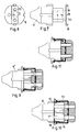
- FIG. 1 to 3 show a protective contact socket 1 with a protective contact clip 2 on a base 3 is attached. Inside the base 3 there are receptacles 4, which are not shown Contact springs for connector pins 5 of a connector 6, cf. 7 and 8. Sitting on the base 3 Socket pot 7 with a cover edge 8. Leg of the protective contact bracket 2 protrude in a known manner into slots in a jacket 9 of the collar 10 of the socket pot 7. In the coat 9 of the collar 10 of the socket pot 7 are in the area of the unmistakable profiles 11 by 90 ° offset the legs of the protective contact bracket 2, axially aligned slots 12 formed.
- a central web 13 of a locking bracket 14 On the end face of the base 3 is a central web 13 of a locking bracket 14 in a vertical orientation attached to the protective contact bracket 2.
- Locking leg 15 of the locking bracket bent at right angles 14 extend in the axial slots 12 and protrude from the front into the interior of the collar 10 into it.
- the locking legs 15 end in bends 16 which are perpendicular to the axis of the collar 10 radially are oriented outwards.
- the plug 6 is designed as a safety plug with edge earthing contacts, which is not in Details are explained.
- the plug 6 is equipped with a coding bracket 17, the two serving as coding profiles 18 Has thighs.
- the essentially flat central web 20 of the coding bracket 17 has passages 19 for the connector pins 5 and lies on the end face of the connector 6.
- Each coding profile 18 has one Surface 20, which is inclined in the direction of insertion against the axis of the plug.
- the central web 20 of the Coding bracket 17 is connected to the plug 6 by an adhesive connection. The plug 6 can therefore can be converted to coding at any time using the coding bracket alone.
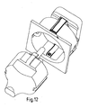
- Fig. 10 shows a connector 6 with coding bracket 17. You can see the coding profiles 18, between enter the locking leg 15 and press the same radially outward, so that the plug of FIG. 11 in the collar of the socket can be inserted.
- Fig. 12 is a perspective view of the connector showing the mutual association of the Shows parts.
- the invention was previously described in a plug-in device with edge earthing contacts. However, the invention is also applicable to a plug-in device with pin earthing contact. This is for the socket shown in FIGS. 4 to 6, without this being explained in detail.
Landscapes
- Details Of Connecting Devices For Male And Female Coupling (AREA)
Applications Claiming Priority (2)
| Application Number | Priority Date | Filing Date | Title |
|---|---|---|---|
| DE10106924 | 2001-02-15 | ||
| DE10106924 | 2001-02-15 |
Publications (1)
| Publication Number | Publication Date |
|---|---|
| EP1237233A1 true EP1237233A1 (fr) | 2002-09-04 |
Family
ID=7674063
Family Applications (1)
| Application Number | Title | Priority Date | Filing Date |
|---|---|---|---|
| EP01104351A Withdrawn EP1237233A1 (fr) | 2001-02-15 | 2001-02-23 | Dispositif de connexion par enfichage avec codage |
Country Status (1)
| Country | Link |
|---|---|
| EP (1) | EP1237233A1 (fr) |
Cited By (1)
| Publication number | Priority date | Publication date | Assignee | Title |
|---|---|---|---|---|
| EP3015641A3 (fr) * | 2014-10-09 | 2016-08-10 | ITT Manufacturing Enterprises LLC | Interconnexion détachable à montage cylindrique |
Citations (2)
| Publication number | Priority date | Publication date | Assignee | Title |
|---|---|---|---|---|
| DE2719841A1 (de) * | 1976-06-09 | 1977-12-22 | Reichle & De Massari Fa | Steckverbindungseinrichtung fuer schwachstromanlagen, insbesondere telefonanlagen |
| DE3906421A1 (de) * | 1989-03-01 | 1990-09-06 | Ackermann Albert Gmbh Co | Verriegelbarer steckverbinder |
-
2001
- 2001-02-23 EP EP01104351A patent/EP1237233A1/fr not_active Withdrawn
Patent Citations (2)
| Publication number | Priority date | Publication date | Assignee | Title |
|---|---|---|---|---|
| DE2719841A1 (de) * | 1976-06-09 | 1977-12-22 | Reichle & De Massari Fa | Steckverbindungseinrichtung fuer schwachstromanlagen, insbesondere telefonanlagen |
| DE3906421A1 (de) * | 1989-03-01 | 1990-09-06 | Ackermann Albert Gmbh Co | Verriegelbarer steckverbinder |
Cited By (2)
| Publication number | Priority date | Publication date | Assignee | Title |
|---|---|---|---|---|
| EP3015641A3 (fr) * | 2014-10-09 | 2016-08-10 | ITT Manufacturing Enterprises LLC | Interconnexion détachable à montage cylindrique |
| US9496649B2 (en) | 2014-10-09 | 2016-11-15 | Itt Manufacturing Enterprises, Llc | Cylindrical mounted break-away interconnect |
Similar Documents
| Publication | Publication Date | Title |
|---|---|---|
| DE10224757B3 (de) | Steckverbinder mit während des Steckvorgangs verrastender Sekundärverriegelung | |
| DE102004030666B4 (de) | Gehäuse zur Aufnahme elektrischer und/oder elektronischer Bauteile | |
| EP0477663B1 (fr) | Pièce de contact | |
| DE10255190B4 (de) | Rundsteckverbindungseinheit | |
| EP1237233A1 (fr) | Dispositif de connexion par enfichage avec codage | |
| EP3143320A1 (fr) | Unité de raccordement destinée à un dispositif d'accouplement, en particulier à un raccord multiple | |
| EP0634601A1 (fr) | Dispositif de raccordement pour accoupler de façon amovible les extrémités de deux tuyaux emboîtables | |
| DE2651334C3 (de) | Elektrische Haltevorrichtung mit in Außerbetriebsteilung abgeschirmten Kontakten, insbesondere Bajonettlampenfassung | |
| DE29521491U1 (de) | Elektrischer Steckverbinder | |
| DE20004194U1 (de) | Steckverbinder zur Leuchtenhalterung | |
| EP3282178B1 (fr) | Connecteur pour un corps de la lampe | |
| DE102021104244A1 (de) | Elektrische Verbindungsvorrichtung | |
| DE29521387U1 (de) | Winkelstecker für elektrische Steckvorrichtungen, insbesondere Kragen- bzw. Rundsteckvorrichtungen | |
| DE29819746U1 (de) | Codierungssystem für Steckverbinder | |
| DE2717354C3 (de) | Verriegelung für Gehäuseteile eines elektrischen Installationsgerätes | |
| AT378865B (de) | Verriegelungselement fuer steckdosen | |
| DE3934440C2 (de) | Zusammensteckbare Kaltlichtspiegelleuchte | |
| EP0269037A2 (fr) | Appareil de protection contre les surtensions | |
| DE8518567U1 (de) | Elektrischer Steckverbinder | |
| DE3420930C2 (fr) | ||
| DE8913930U1 (de) | Elektrische Fassung, insbesondere für Lampen | |
| DE3721679A1 (de) | Steckanschluss | |
| DE20205811U1 (de) | Steckverbinder | |
| DE19623645B4 (de) | Elektrische Anschlußklemme | |
| DE1639098C (fr) |
Legal Events
| Date | Code | Title | Description |
|---|---|---|---|
| PUAI | Public reference made under article 153(3) epc to a published international application that has entered the european phase |
Free format text: ORIGINAL CODE: 0009012 |
|
| AK | Designated contracting states |
Kind code of ref document: A1 Designated state(s): AT BE CH CY DE DK ES FI FR GB GR IE IT LI LU MC NL PT SE TR |
|
| AX | Request for extension of the european patent |
Free format text: AL;LT;LV;MK;RO;SI |
|
| AKX | Designation fees paid | ||
| REG | Reference to a national code |
Ref country code: DE Ref legal event code: 8566 |
|
| STAA | Information on the status of an ep patent application or granted ep patent |
Free format text: STATUS: THE APPLICATION IS DEEMED TO BE WITHDRAWN |
|
| 18D | Application deemed to be withdrawn |
Effective date: 20030305 |