EP1236976B1 - Dosiergerät zum Abgeben von Flüssigkeitvolumina - Google Patents
Dosiergerät zum Abgeben von Flüssigkeitvolumina Download PDFInfo
- Publication number
- EP1236976B1 EP1236976B1 EP02004527.4A EP02004527A EP1236976B1 EP 1236976 B1 EP1236976 B1 EP 1236976B1 EP 02004527 A EP02004527 A EP 02004527A EP 1236976 B1 EP1236976 B1 EP 1236976B1
- Authority
- EP
- European Patent Office
- Prior art keywords
- suction
- delivery
- valve
- check valve
- dosing device
- Prior art date
- Legal status (The legal status is an assumption and is not a legal conclusion. Google has not performed a legal analysis and makes no representation as to the accuracy of the status listed.)
- Expired - Lifetime
Links
Images


Classifications
-
- B—PERFORMING OPERATIONS; TRANSPORTING
- B05—SPRAYING OR ATOMISING IN GENERAL; APPLYING FLUENT MATERIALS TO SURFACES, IN GENERAL
- B05B—SPRAYING APPARATUS; ATOMISING APPARATUS; NOZZLES
- B05B11/00—Single-unit hand-held apparatus in which flow of contents is produced by the muscular force of the operator at the moment of use
- B05B11/0005—Components or details
- B05B11/0062—Outlet valves actuated by the pressure of the fluid to be sprayed
- B05B11/0064—Lift valves
-
- F—MECHANICAL ENGINEERING; LIGHTING; HEATING; WEAPONS; BLASTING
- F04—POSITIVE - DISPLACEMENT MACHINES FOR LIQUIDS; PUMPS FOR LIQUIDS OR ELASTIC FLUIDS
- F04B—POSITIVE-DISPLACEMENT MACHINES FOR LIQUIDS; PUMPS
- F04B13/00—Pumps specially modified to deliver fixed or variable measured quantities
-
- F—MECHANICAL ENGINEERING; LIGHTING; HEATING; WEAPONS; BLASTING
- F04—POSITIVE - DISPLACEMENT MACHINES FOR LIQUIDS; PUMPS FOR LIQUIDS OR ELASTIC FLUIDS
- F04B—POSITIVE-DISPLACEMENT MACHINES FOR LIQUIDS; PUMPS
- F04B53/00—Component parts, details or accessories not provided for in, or of interest apart from, groups F04B1/00 - F04B23/00 or F04B39/00 - F04B47/00
- F04B53/10—Valves; Arrangement of valves
- F04B53/1002—Ball valves
-
- G—PHYSICS
- G01—MEASURING; TESTING
- G01F—MEASURING VOLUME, VOLUME FLOW, MASS FLOW OR LIQUID LEVEL; METERING BY VOLUME
- G01F11/00—Apparatus requiring external operation adapted at each repeated and identical operation to measure and separate a predetermined volume of fluid or fluent solid material from a supply or container, without regard to weight, and to deliver it
- G01F11/02—Apparatus requiring external operation adapted at each repeated and identical operation to measure and separate a predetermined volume of fluid or fluent solid material from a supply or container, without regard to weight, and to deliver it with measuring chambers which expand or contract during measurement
- G01F11/021—Apparatus requiring external operation adapted at each repeated and identical operation to measure and separate a predetermined volume of fluid or fluent solid material from a supply or container, without regard to weight, and to deliver it with measuring chambers which expand or contract during measurement of the piston type
- G01F11/025—Apparatus requiring external operation adapted at each repeated and identical operation to measure and separate a predetermined volume of fluid or fluent solid material from a supply or container, without regard to weight, and to deliver it with measuring chambers which expand or contract during measurement of the piston type with manually operated pistons
- G01F11/028—Apparatus requiring external operation adapted at each repeated and identical operation to measure and separate a predetermined volume of fluid or fluent solid material from a supply or container, without regard to weight, and to deliver it with measuring chambers which expand or contract during measurement of the piston type with manually operated pistons the dosing device being provided with a dip tube and fitted to a container, e.g. to a bottleneck
-
- B—PERFORMING OPERATIONS; TRANSPORTING
- B05—SPRAYING OR ATOMISING IN GENERAL; APPLYING FLUENT MATERIALS TO SURFACES, IN GENERAL
- B05B—SPRAYING APPARATUS; ATOMISING APPARATUS; NOZZLES
- B05B11/00—Single-unit hand-held apparatus in which flow of contents is produced by the muscular force of the operator at the moment of use
- B05B11/01—Single-unit hand-held apparatus in which flow of contents is produced by the muscular force of the operator at the moment of use characterised by the means producing the flow
- B05B11/10—Pump arrangements for transferring the contents from the container to a pump chamber by a sucking effect and forcing the contents out through the dispensing nozzle
- B05B11/1001—Piston pumps
- B05B11/1015—Piston pumps actuated without substantial movement of the nozzle in the direction of the pressure stroke
-
- B—PERFORMING OPERATIONS; TRANSPORTING
- B05—SPRAYING OR ATOMISING IN GENERAL; APPLYING FLUENT MATERIALS TO SURFACES, IN GENERAL
- B05B—SPRAYING APPARATUS; ATOMISING APPARATUS; NOZZLES
- B05B11/00—Single-unit hand-held apparatus in which flow of contents is produced by the muscular force of the operator at the moment of use
- B05B11/01—Single-unit hand-held apparatus in which flow of contents is produced by the muscular force of the operator at the moment of use characterised by the means producing the flow
- B05B11/10—Pump arrangements for transferring the contents from the container to a pump chamber by a sucking effect and forcing the contents out through the dispensing nozzle
- B05B11/1042—Components or details
- B05B11/1066—Pump inlet valves
Definitions
- the invention relates to a dosing device for dispensing a preset volume of liquid from a container having the features of the preamble of claim 1, claim 8 or claim 12.
- the known dosing device from which the invention proceeds ( DE-A-23 43 687 ), is a bottle dispenser for dispensing liquids with a glass cylinder in which an adjustable piston for sucking an adjustable amount of liquid slides, and a valve head having disposed therein each a suction and discharge check valve, which are - also with the glass cylinder - in fluid communication.
- These valves are arranged in fluid communication between a container and a discharge opening so that they open in the discharge direction and block the fluid flow in the reverse direction.
- Leading upstream from the suction shut-off valve is a suction duct in the form of a tube or hose, which generally extends to near the bottom of the container.
- the discharge check valve is followed downstream as well as a usually angled piece of pipe, an ejection cannula, which ends with the liquid outlet.
- the piston of this dispenser is provided with a coating, preferably made of PTFE, and easily slidably guided in the cylinder with a small gap between the cylinder inner wall and piston outer surface.
- the suction check valve opens and the liquid flows via the suction line from the container into the expanding displacement chamber.
- the raised piston with its own weight remains in a position as the valve body of the discharge check valve is urged against the valve seat with a valve spring.
- the dispensing check valve opens due to the fluid pressure, and the fluid flows out of the displacer through the dispensing check valve and the ejection cannula out of the fluid outlet.
- the adjustable suction stroke is limited by a rigidly attached to the cylinder stop ring and a piston adjustable and lockable stop segment.
- Bottle dispensers of this type are presently operated by hand and are under normal use an accurate volumeter.
- sealless and thus smooth piston-cylinder arrangement can then problems occur when the piston is driven with increased lifting speed against the respective stop. This can happen, in particular, if the adjustable liquid volume is reduced or the suction stroke is shortened.
- the movement of movement of the piston causes a flow of liquid in the lines of the fluid connection and the suction line or the ejection cannula. Due to the abrupt stopping of the piston stroke, a pressure increase due to the flow energy, which can lead to both shut-off valves open and an indefinite amount of liquid is discharged.
- a metering device with Ansaugsperrventil and Abgabesperrventil and with additional Umströmungs stresses for better management of the valve body is from the FR-E-45955 known.
- the US-A-4,072,247 also shows a metering device of a similar nature, in which there is a lateral offset between the intake and the Ansaugsperrventil on the one hand and the piston-cylinder assembly of the displacer unit on the other.
- the object of the invention is to design the above-mentioned metering device of the type in question so that the accuracy of the dispensed fluid volume is more independent of the operation.
- the invention is based on the idea of not conducting the flow energy of the fluid in the lines which is to be broken down when the piston stroke is abruptly stopped into the ejection cannula.
- the discharge line can be closed (claims 1), the energy is absorbed (claim 8) or excess fluid are derived (claim 12).
- the blocking body by its flow resistance in the fluid flow between the Ansaugsperrventil and the Displacer, which flows around or flows through him, be moved into the respective positions.
- the blocking body may instead or additionally be urged by an associated compression spring into the occluding first positive cone. In the dispensing process, the blocking body is displaced by the fluid flow in the opposite direction in the second position.
- the intake valve seat of the Ansaugsperrventils is used as a blocking body.
- This is arranged in a valve sleeve, which has a preferably frontally molded stop.
- the valve sleeve has at least one radially aligned bore located in the lateral surface. This has the function of the discharge opening. It preferably has at its outer periphery at the level of this bore a circumferential groove. The bore or groove is in fluid communication with the dispensing line.
- the flow energy is attenuated in the intake before the Ansaugsperrventil.
- a flexible and expanding wall is preferably arranged near this valve in the suction line, which deforms at a pressure increase in order to accommodate a liquid volume can. This amount of liquid taken up for braking the liquid column runs back into the storage container in the subsequent contraction phase of the element via the suction line.
- the flexible wall in the suction line can be designed as bellows-like and / or membrane-like element or have a damping element in the form of a piston-cylinder arrangement for receiving pressure surges.
- a pressure relief valve in the suction line is preferably arranged close to the suction check valve. Over this the flow energy at the end of the intake process is derived.
- the pressure relief valve opens at a pressure rise, so that the flow energy is dissipated as effluent.
- Fig. 1a an inventive dosing device 1 is shown, which can suck in and deliver a preset volume of liquid from a container of a displacer unit 2.
- the dosing device 1 is driven by a change-manual operation, in addition to the manual operation and mechanical drives are conceivable that can show no reduction in the operating speed before approaching stops.
- the displacer unit 2 has a piston 3 which is fitted in a cylinder 4 in such a way that the gap seals via capillary forces of the liquid.
- the piston 3 is designed to be displaceable, so that a variable in volume displacement chamber 5 is present. Not shown are the actuator and the volume adjustment to a corresponding housing.
- the displacer unit 2 is fixedly connected to the valve housing 6 via the cylinder 4.
- this blocking valves are arranged as Ansaugsperrventil 7 with Ansaugventilkugel 8 and intake valve seat 9 and as a discharge check valve 10 to control the liquid flow in the discharge direction.
- the discharge check valve 10 may also, as in Fig. 1a shown, in which releasably connected to the valve housing 6 ejection cannula 11 are located.
- a rotatable and captive union nut 12 is attached to the valve housing 6.
- an intake 13 which is fixed at its end facing the metering device 1 to the housing of the Ansaugsperrventils 7.
- the suction line 13 may also be coupled to a supply line.
- the Fig. 1a shows the dosing device 1 in the suction process.
- the Ansaugsperrventil 7 opens and the liquid flows into the displacement chamber 5.
- the suction ends with the approach to a stop of the volume adjustment, so that the piston 3 stops and the liquid flow from the suction line 13 is abruptly decelerated.
- a blocking body 15 is movably arranged in the fluid connection between the displacement chamber 5 and the Ansaugsperrventil 7, which flows in the suction of the liquid flow and / or flows through and is preferably driven by its flow resistance , All directions of movement such as longitudinal and / or rotating as well as any necessary motion control are technically feasible; it is essential that the blocking body 15 is displaced before the discharge opening 16 of the discharge line 14. In this first position, the blocking body 15 closes the dispensing opening 16.
- the displacement movement can also be assisted or effected by a spring, not shown, expediently a compression spring, wherein the blocking body 15 is urged into its first position with a higher closure force.
- the locking body 15 decreases due to its own weight, before the dispensing operation from the first closing position to the second, the discharge line 14 releasing position, the in Fig. 1b is shown.
- the blocking body 15 is urged at the beginning of the discharge process - analogous to the intake - by its flow resistance and possibly against the force of the compression spring in the second position.
- Fig. 1b shows the dosing device 1 in the dispensing process.
- the liquid flows from the displacement chamber 5, through the discharge line 14 in the direction of arrow over the - due to the pressure - open discharge check valve 10 in the ejection 11 and through the liquid outlet 17 in a, indicated by another arrow, but not shown Aufnabmegefäß.
- a blocking body 15 of the intake valve seat 9 in a valve sleeve 20 which is fixedly connected to the valve housing 6, mounted sealingly movable.
- a further valve seat on the outside which corresponds to a sealing surface 21 on the valve bush 20, is incorporated on the intake valve seat 9.
- This sealing surface also serves as a stop 21 for the intake valve seat 9, which is urged by a compression spring 22 against it.
- the valve sleeve 20 carries in its cylindrical wall radially machined holes 23 which open into a circumferential groove on the outer surface of the cylindrical wall. These act as a delivery opening. The groove is in fluid communication with the discharge line 14.
- the intake valve seat 9 In the intake process, the intake valve seat 9 with its other valve seat sealingly against the valve sleeve 20 and thereby closes the discharge line 14.
- the liquid under pressure can not escape through the closed Ansaugsperrventil 7 and pushes it like a piston from the stop 21 away so far into the valve sleeve 20 until the radial bores 23 are exposed, so that the liquid can flow through this and in the groove converging in the discharge line 14.
- a bellows-like element assumes the function of the compression spring.
- the Ansaugventilsitz 9 is held on its outer surface of this element in order to perform the function of the valve sleeve - the sealing movement guide - can.
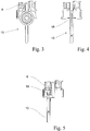
- the 3 and 4 show a further proposed solution in a preferred variant of the suction line 13.
- the flow energy at the end of the intake before the Ansaugsperrventil 7 is attenuated.
- a flexible and expanding wall is arranged near the Ansaugsperrrventil 7 in the suction line 13, which deforms at a pressure increase to absorb a volume of liquid can. This amount of liquid taken up for braking the liquid column runs back into the container via the suction line 13 in the subsequent contraction phase of the wall.
- the flexible wall 18 in the suction line 13 may be made single or multiple and bellows-like or membrane-like.
- Fig. 4 are the constricted and thus more flexible walls 18 shown with the arrows indicated by expansion directions.
- the suction pipe 13 is generally made as a tube made of a thermoplastic material. This plastic is ideally suited to inexpensively produce such a suction line 13 by hot deformation.
- a fluid volume is absorbed by a damping arrangement, as known to those skilled in fluid line systems at a pressure increase.
- the Fig. 5 shows a further solution, in which the flow energy at the end of the intake before the intake valve 7 is derived.
- a pressure relief valve 19 is arranged in the suction line 13, that the liquid column to be braked pushes straight into the pressure relief valve 19, this opens and the flow energy in the form of a liquid surge in the container is dismantled back.
- a non-return valve which opens with minimal differential pressure and automatically closes due to the negative pressure in the intake line 13 and automatically vents itself via the pressure surges as well.
Landscapes
- Engineering & Computer Science (AREA)
- Mechanical Engineering (AREA)
- General Engineering & Computer Science (AREA)
- Physics & Mathematics (AREA)
- Fluid Mechanics (AREA)
- General Physics & Mathematics (AREA)
- Containers And Packaging Bodies Having A Special Means To Remove Contents (AREA)
Description
- Die Erfindung betrifft ein Dosiergerät zum Abgeben eines voreingestellten Flüssigkeitsvolumens aus einem Behälter mit den Merkmalen des Oberbegriffs von Anspruch 1, von Anspruch 8 oder von Anspruch 12.
- Das bekannte Dosiergerät, von dem die Erfindung ausgeht (
DE-A-23 43 687 ), ist ein Flaschendispenser zur Abgabe von Flüssigkeiten mit einem Glaszylinder, in dem ein verstellbarer Kolben zum Ansaugen einer einstellbaren Flüssigkeitsmenge gleitet, sowie einem Ventilkopf mit darin angeordnet je einem Ansaug- und Abgabesperrventil, die - auch mit dem Glaszylinder - in Fluidverbindung stehen. Diese Ventile sind in Fluidverbindung zwischen einem Behältnis und einer Abgabeöffnung so angeordnet, dass sie in Abgaberichtung öffnen und in umgekehrter Richtung den Fluidstrom versperren. Vom Ansaugsperrventil stromaufwärts führend ist eine Ansaugleitung in Form eines Rohres oder Schlauches angeschlossen, die sich im allgemeinen bis nahe dem Behälterboden erstreckt. Dem Abgabesperrventil folgt stromabwärts ebenso ein meist abgewinkeltes Rohrstück, eine Ausstoßkanüle, die mit dem Flüssigkeitsauslass endet. Der Kolben dieses Dispensers ist mit einem Überzug, vorzugsweise aus PTFE, versehen und mit geringem Spalt zwischen der Zylinderinnenwand und Kolbenaußenfläche in dem Zylinder leicht verschiebbar geführt. - Wird der Kolben aus dem Zylinder gezogen, so öffnet das Ansaugsperrventil und die Flüssigkeit strömt über die Ansaugleitung vom Behälter in den expandierenden Verdrängerraum. Der hochgezogene Kolben mit seinem Eigengewicht verbleibt in der Lage, da der Ventilkörper des Abgabesperrventils mit einer Ventilfeder gegen den Ventilsitz gedrängt wird. Wird der Kolben niedergedrückt, so öffnet das Abgabesperrventil aufgrund des Flüssigkeitsdruckes, und die Flüssigkeit strömt aus dem Verdrängerraum durch das Abgabesperrventil und die Ausstoßkanüle aus dem Flüssigkeitsauslass.
- Der einstellbare Saughub wird durch einen starr am Zylinder befestigten Anschlagring und ein am Kolben verstell- und arretierbares Anschlagsegment begrenzt.
- Flaschendispenser dieser Art werden vorliegend von Hand betätigt und sind bei bestimmungsgemäßem Gebrauch ein genaues Volumenmessgerät. Durch die dichtungslose und somit leichtgängige Kolben-Zylinder-Anordnung können allerdings dann Probleme auftreten, wenn der Kolben mit erhöhter Hubgeschwindigkeit gegen den jeweiligen Anschlag gefahren wird. Dies kann insbesondere dann geschehen, wenn das verstellbare Flüssigkeitsvolumen verringert bzw. der Saughub verkürzt wird.
- Die Verfahrbewegung des Kolbens bewirkt eine Flüssigkeitsströmung in den Leitungen der Fluidverbindung und der Ansaugleitung bzw. der Ausstoßkanüle. Durch das abrupte Abstoppen des Kolbenhubes entsteht aufgrund der Strömungsenergie ein Druckanstieg, der dazu führen kann, dass beide Sperrventile öffnen und eine unbestimmte Flüssigkeitsmenge abgegeben wird.
- Es bestünde die Möglichkeit, statt Sperrventilen Wegeventile einzusetzen, um die Leitungsverbindung entweder vom Verdrängerraum zur Ansaugleitung oder zur Abgabeleitung zu erreichen. Ein derartiger Aufbau hätte aber die Nachteile, dass die Stellungen des Wegeventils geschaltet werden müssten, dadurch Bedienfehler auftreten könnten und bei Handbetätigung ein Umgreifen an das jeweilige Bedienteil erforderlich wäre, da zum einen bei der Betätigung des Kolbens und zum anderen bei dem Halten eines Aufnahmegefäßes unter den Flüssigkeitsauslaß je eine Hand des Bedieners benötigt wird.
- Eine weitere Möglichkeit bestünde darin, die Strömungsverhältnisse in der Ansaug- und/oder Abgabeleitung in Form ihres Querschnitts in Relation zum Kolbenquerschnitt vorzugeben. Je größer der Querschnitt ist, desto geringer wird die Strömungsgeschwindigkeit und folglich auch die Strömungsenergie. Jedoch wurde festgestellt, dass die Volumengenauigkeit negativ beeinflusst wird und die Entlüftung beim erstmaligen Befüllen schwieriger durchführbar bzw. wegen nicht herausspülbarer Luftblasen unvollständiger wird.
- Es besteht auch die Möglichkeit, für den Kolben vor dem Anfahren auf den Anschlag ein Abbremsen einzurichten. Jedoch hängt der Erfolg einer vollständigen Entlüftung ebenso von der leichtgängigen Anfahrt in der eintauchenden Bewegungsrichtung auf den Kolbenanschlag ab. Auch wirken sich die zusätzlichen und ungleichmäßigen Kräfte nachteilig auf den Bedienkomfort aus.
- Ein Dosiergerät mit Ansaugsperrventil und Abgabesperrventil und mit zusätzlichen Umströmungskörpern zur besseren Führung der Ventilkörper ist aus der
FR-E-45.955 - Die
US-A-4,072,247 zeigt ebenfalls ein Dosiergerät ähnlicher Art, bei dem ein seitlicher Versatz zwischen der Ansaugleitung und dem Ansaugsperrventil einerseits und der Kolben-Zylinder-Anordnung der Verdrängereinheit andererseits vorliegt. - Einen Ventilblock eines Dosiergerätes der in Rede stehenden Art, bei dem das Ansaugsperrventil einerseits und das Abgabesperrventil andererseits in auswechselbaren Einsätzen angeordnet sind, zeigt die
DE-A-195 36 258 . Ähnliches zeigt auch dieGB-A-711,879 - Die Aufgabe der Erfindung ist es, das eingangs angesprochene Dosiergerät der in Rede stehenden Art so auszugestalten, dass die Genauigkeit des abgegebenen Flüssigkeitsvolumens unabhängiger von der Bedienung wird.
- Diese Aufgabe wird in drei nebengeordneten, auf demselben Grundgedanken beruhenden Varianten mit den Merkmalen der Ansprüche 1, 8 und 12 gelöst.
- Die Erfindung geht von dem Grundgedanken aus, die beim abrupten Abstoppen des Kolbenhubes abzubauende Strömungsenergie des Fluids in den Leitungen nicht in die Ausstoßkanüle zu leiten. Hierzu kann die Abgabeleitung verschlossen werden (Ansprüche 1), die Energie gedämpft werden (Anspruch 8) oder überschüssiges Fluid abgeleitet werden (Anspruch 12).
- In der Variante von Anspruch 1 wird verhindert, dass der beim Abbauen der Strömungsenergie entstehende Druckanstieg das federunterstützte Abgabesperrventil öffnet. Somit wird erreicht, dass kein Flüssigkeitsvolumen unbeabsichtigt und unerwartet durch die Abgabeöffnung entweicht.
- Bei einer bevorzugten Ausführungsform kann der Sperrkörper durch seinen Strömungswiderstand im Fluidstrom zwischen dem Ansaugsperrventil und dem Verdrängerraum, welcher ihn um- oder durchströmt, in die jeweiligen Positionen verlagert werden.
- Bei einer bevorzugten Ausführungsform kann der Sperrkörper statt dessen oder zusätzlich durch eine zugeordnete Druckfeder in die verschließende erste Positivon gedrängt werden. Im Abgabevorgang wird der Sperrkörper durch den Fluidstrom in Gegenrichtung in die zweite Position verlagert.
- In einer Variante wird der Ansaugventilsitz des Ansaugsperrventils als Sperrkörper verwendet. Dieser ist dazu in einer Ventilbuchse angeordnet, die einen vorzugsweise stirnseitig angeformten Anschlag aufweist. Die Ventilbuchse weist mindestens eine in der Mantelfläche befindliche, radial ausgerichtete Bohrung auf. Diese hat die Funktion der Abgabeöffnung. Sie hat vorzugsweise an ihrem äußeren Umfang in Höhe dieser Bohrung eine umlaufende Nut. Die Bohrung bzw. die Nut steht in Fluidverbindung mit der Abgabeleitung.
- Nach einem weiteren erfindungsgemäßen Lösungsvorschlag (Anspruch 8) wird die Strömungsenergie im Ansaugvorgang vor dem Ansaugsperrventil gedämpft. Hierzu ist vorzugsweise nahe diesem Ventil in der Ansaugleitung eine flexible und expandierende Wandung angeordnet, welche sich bei einem Druckanstieg verformt, um ein Flüssigkeitsvolumen aufnehmen zu können. Diese zum Bremsen der Flüssigkeitssäule aufgenommene Flüssigkeitsmenge läuft in der anschließenden Kontraktionsphase des Elementes über die Ansaugleitung wieder in den Vorratsbehälter zurück.
- Bei bevorzugten Ausführungsformen kann die flexible Wandung in der Ansaugleitung als faltenbalgartiges und/oder membranartiges Element ausgeführt sein oder ein Dämpfungselement in Form einer Kolben-Zylinder-Anordnung zur Aufnahme von Druckstößen aufweisen.
- Nach einem weiteren erfindungsgemäßen Lösungsvorschlag (Anspruch 12) wird ein Überdruckventil in der Ansaugleitung vorzugsweise nahe dem Ansaugsperrventil angeordnet. Hierüber wird die Strömungsenergie am Ende des Ansaugvorganges abgeleitet. Das Überdruckventil öffnet bei einem Druckanstieg, so dass die Strömungsenergie als ausströmende Flüssigkeit abgebaut wird.
- Die Erfindung wird nachfolgend anhand der anliegenden Zeichnungen bevorzugter Ausführungen näher erläutern. In den Zeichnungen zeigt:
- Fig. 1a
- ein Dosiergerät in Form eines Flaschendispensers entsprechend dem ersten Lösungsvorschlag im Ansaugvorgang, in Schnittdarstellung,
- Fig. 1b
- das Dosiergerät aus
Fig. 1a im Abgabevorgang, - Fig. 2a
- ein Dosiergerät in Form eines Flaschendispensers in einer Variante des ersten Lösungsvorschlags im Ansaugvorgangs, in Schnittdarstellung,
- Fig. 2b
- das Dosiergerät aus
Fig. 2a im Abgabevorgang, - Fig. 3
- ein Dosiergerät in Form eines Flaschendispensers entsprechend dem zweiten Lösungsvorschlag, in detaillierter Schnittdarstellung,
- Fig. 4
- das Dosiergerät aus
Fig. 3 , in 90° gedrehter Schnittdarstellung, - Fig. 5
- ein Dosiergerät in Form eines Flaschendispensers entsprechend dem dritten Lösungsvorschlag, in detaillierter Schnittdarstellung.
- In
Fig. 1a ist ein erfindungsgemäßes Dosiergerät 1 dargestellt, das ein voreingestelltes Flüssigkeitsvolumen aus einem Behälter von einer Verdrängereinheit 2 ansaugen und abgeben kann. Das Dosiergerät 1 wird über eine wechselsinnige manuelle Betätigung angetrieben, wobei neben der Betätigung per Hand auch maschinelle Antriebe denkbar sind, die keine Reduzierung der Betätigungsgeschwindigkeit vor der Anfahrt auf Anschläge vorweisen können. - Die Verdrängereinheit 2 hat einen Kolben 3, der so in einen Zylinder 4 eingepasst ist, dass der Spalt über Kapillarkräfte der Flüssigkeit abdichtet. Der Kolben 3 ist verschiebbar ausgeführt, so dass ein im Volumen veränderlicher Verdrängerraum 5 vorliegt. Nicht dargestellt sind die Betätigungseinrichtung und die Volumenverstellung an einem entsprechenden Gehäuse.
- Die Verdrängereinheit 2 ist über den Zylinder 4 mit dem Ventilgehäuse 6 fest verbunden. In diesem sind Sperrventile als Ansaugsperrventil 7 mit Ansaugventilkugel 8 und Ansaugventilsitz 9 und als Abgabesperrventil 10 angeordnet, um den Flüssigkeitsstrom in Abgaberichtung zu steuern. Das Abgabesperrventil 10 kann sich auch, wie in
Fig. 1a dargestellt, in der lösbar mit dem Ventilgehäuse 6 verbundenen Ausstoßkanüle 11 befinden. - Zur Befestigung des Dosiergerätes 1 an einem nicht dargestellten Behälter oder einer Befestigungskonsole ist an dem Ventilgehäuse 6 eine drehbare und unverlierbare Überwurfmutter 12 angebracht. In den Behälter ragt eine Ansaugleitung 13, die an ihrem dem Dosiergerät 1 zugewandten Ende an dem Gehäuse des Ansaugsperrventils 7 befestigt ist. Die Ansaugleitung 13 kann auch mit einer Vorratsleitung gekoppelt sein.
- Die
Fig. 1a zeigt das Dosiergerät 1 im Ansaugvorgang. Dabei wird der Kolben 3, wie durch den Pfeil angedeutet, im Zylinder 4 nach oben gezogen, so dass im Verdrängerraum 5 ein Unterdruck entsteht, der die zu dosierende Flüssigkeit aus der Ansaugleitung 13, wie der dortige Pfeil zeigt, ansaugt. Das Ansaugsperrventil 7 öffnet und die Flüssigkeit strömt in den Verdrängerraum 5. Der Ansaugvorgang endet mit der Anfahrt auf einen Anschlag der Volumenverstellung, so dass der Kolben 3 stoppt und der Flüssigkeitsstrom aus der Ansaugleitung 13 abrupt abgebremst wird. - Um zu verhindern, dass der Flüssigkeitsstrom in die Abgabeleitung 14 fließt, ist ein Sperrkörper 15 in der Fluidverbindung zwischen dem Verdrängerraum 5 und dem Ansaugsperrventil 7 beweglich angeordnet, der im Ansaugvorgang von dem Flüssigkeitsstrom um- und/oder durchströmt und vorzugsweise durch seinen Strömungswiderstand angetrieben wird. Alle Bewegungsrichtungen wie längs und/oder drehend sowie eine eventuell notwendige Bewegungsführung sind technisch ausführbar; wesentlich ist, dass der Sperrkörper 15 vor die Abgabeöffnung 16 der Abgabeleitung 14 verlagert wird. In dieser ersten Position verschließt der Sperrkörper 15 die Abgabeöffnung 16.
- Die Verlagerungsbewegung kann auch durch eine nicht dargestellte Feder, zweckmäßigerweise eine Druckfeder, unterstützt oder bewirkt werden, wobei der Sperrkörper 15 in seine erste Position mit höherer Verschlusskraft gedrängt wird.
- Der Sperrkörper 15 sinkt, bedingt durch sein Eigengewicht, vor dem Abgabevorgang von der ersten verschließenden Position in die zweite, die Abgabeleitung 14 freigebende Position, die in
Fig. 1b dargestellt ist. Alternativ wird der Sperrkörper 15 beim Beginn des Abgabevorgangs - analog des Ansaugvorgangs - durch seinen Strömungswiderstand und ggf. entgegen der Kraft der Druckfeder in die zweite Position gedrängt. -
Fig. 1b zeigt das Dosiergerät 1 im Abgabevorgang. Dabei wird der Kolben 3, wie durch den Pfeil angedeutet, verlagert, so dass im Verdrängerraum 5 ein Überdruck entsteht. Die Flüssigkeit strömt aus dem Verdrängerraum 5, durch die Abgabeleitung 14 in Pfeilrichtung über das - bedingt durch den Überdruck - geöffnete Abgabesperrventil 10 in die Ausstoßkanüle 11 und durch den Flüssigkeitsauslass 17 in ein, von einem weiteren Pfeil angedeutetes, jedoch nicht dargestelltes Aufnabmegefäß. - In der Variante, die in
Fig. 2a und 2b gezeigt ist, ist als Sperrkörper 15 der Ansaugventilsitz 9 in einer Ventilbuchse 20, die fest mit dem Ventilgehäuse 6 verbunden ist, dichtend beweglich gelagert. An dem Ansaugventilsitz 9 ist neben dem Ventilsitz für die Ansaugventilkugel 8 ein weiterer Ventilsitz an der Außenseite eingearbeitet, der einer Dichtfläche 21 an der Ventilbuchse 20 entspricht. Diese Dichtfläche dient auch als Anschlag 21 für den Ansaugventilsitz 9, der von einer Druckfeder 22 dagegen gedrängt wird. Die Ventilbuchse 20 trägt in ihrer zylindrischen Wand radial eingearbeitete Bohrungen 23, die in eine umlaufende Nut an der Außenfläche der zylindrischen Wand münden. Diese wirken als Abgabeöffhung. Die Nut steht in Fluidverbindung mit der Abgabeleitung 14. - Im Ansaugvorgang liegt der Ansaugventilsitz 9 mit seinem weiteren Ventilsitz dichtend an der Ventilbuchse 20 an und verschließt dadurch die Abgabeleitung 14. Im Abgabevorgang kann die unter Überdruck stehende Flüssigkeit nicht durch das verschlossene Ansaugsperrventil 7 entweichen und drängt es wie ein Kolben vom Anschlag 21 weg so weit in die Ventilbuchse 20 hinein, bis die Radialbohrungen 23 freiliegen, so dass die Flüssigkeit durch diese und in der Nut zusammenlaufend in die Abgabeleitung 14 strömen kann.
- In einer alternativen Ausführungsform dieser Variante übernimmt ein faltenbalgartiges Element die Funktion der Druckfeder. Der Ansaugventilsitz 9 wird an seiner Außenfläche von diesem Element gehalten, um die Funktion der Ventilbuchse - der dichtenden Bewegungsführung - ausführen zu können.
- Die
Fig. 3 und 4 zeigen einen weiteren Lösungsvorschlag in einer bevorzugten Variante der Ansaugleitung 13. Bei diesem Lösungsvorschlag wird die Strömungsenergie am Ende des Ansaugvorgangs vor dem Ansaugsperrventil 7 gedämpft. Hierzu ist nahe dem Ansaugsperrrventil 7 in der Ansaugleitung 13 eine flexible und expandierende Wandung angeordnet, welche sich bei einem Druckanstieg verformt, um ein Flüssigkeitsvolumen aufnehmen zu können. Diese zum Bremsen der Flüssigkeitssäule aufgenommene Flüssigkeitsmenge läuft in der anschließenden Kontraktionsphase der Wandung über die Ansaugleitung 13 wieder in den Behälter zurück. - Die flexible Wandung 18 in der Ansaugleitung 13 kann einzeln oder mehrfach und faltenbalgartig oder membranartig ausgeführt sein. In
Fig. 4 sind die eingeschnürten und damit flexibleren Wandungen 18 mit den über Pfeile angedeuteten Expansionsrichtungen dargestellt. Die Ansaugleitung 13 ist im allgemeinen als Rohr aus einem thermoplastischen Kunststoff hergestellt. Dieser Kunststoff ist hervorragend geeignet, um eine solche Ansaugleitung 13 durch Warmverformung kostengünstig herzustellen. - Ebenso wie durch die flexible Wandung wird bei einem Druckanstieg ein Flüssigkeitsvolumen durch eine Dämpfungsanordnung, wie sie dem Fachmann bei Fluidleitungssystemen bekannt sind, aufgenommen.
- Die
Fig. 5 zeigt einen weiteren Lösungsvorschlag, bei dem die Strömungsenergie am Ende des Ansaugvorgangs vor dem Ansaugventil 7 abgeleitet wird. Hierbei ist ein Überdruckventil 19 so in der Ansaugleitung 13 angeordnet, dass die abzubremsende Flüssigkeitssäule geradlinig in das Überdruckventil 19 drängt, dieses öffnet und die Strömungsenergie in Form eines Flüssigkeitsschwalls in den Behälter zurück abgebaut wird. Vorteilhaft ist ein mit minimalem Differenzdruck öffnendes Rückschlagventil, das bedingt durch den Unterdruck in der Ansaugleitung 13 selbsttätig verschließt und sich über die Druckstöße ebenso selbsttätig entlüftet.
Claims (13)
- Dosiergerät zum Abgeben eines voreingestellten Flüssigkeitsvolumens aus einem Behälter,
mit einer Verdrängereinheit (2), der vor- und nachgeschaltete Sperrventile (7; 10), nämlich ein Ansaugsperrventil (7) und ein Abgabesperrventil (10), zugeordnet sind, die den Flüssigkeitsstrom steuern und über eine Fluidverbindung verfügen, wobei durch eine wechselsinnige Betätigung der Verdrängereinheit (2) ein Flüssigkeitsvolumen in einem Ansaugvorgang aus einer Ansaugleitung (13) über das Ansaugsperrventil (7) mit einem Ansaugventilsitz (9) und die Fluidverbindung in einen Verdrängerraum (5) der Verdrängereinheit (2) ansaugbar und in einem Abgabevorgang aus dem Verdrängerraum (5) über die eine Abgabeleitung (14) aufweisende Fluidverbindung und das Abgabesperrventil (10) zu einem Flüssigkeitsauslass (17) hin abgebbar ist, wobei die Abgabeleitung (14) mit einer Abgabeöffnung (16; 23) von der Fluidverbindung zwischen dem Ansaugsperrventil (7) und dem Verdrängerraum (5) abzweigt,
dadurch gekennzeichnet,
dass in der Fluidverbindung ein Sperrkörper (15) beweglich angeordnet ist, der im Ansaugvorgang in einer ersten Position die Abgabeöffnung (16; 23) verschließt und im Abgabevorgang in einer zweiten Position die Abgabeöffnung (16; 23) freigibt. - Dosiergerät nach Anspruch 1, dadurch gekennzeichnet,
dass der Sperrkörper (15) in der Fluidverbindung zwischen dem Verdrängerraum (5) und dem Ansaugsperrventil (7) angeordnet ist und durch seinen Strömungswiderstand in einem Fluidstrom, welcher ihn um- oder durchströmt, verlagerbar ist. - Dosiergerät nach Anspruch 1 oder 2, dadurch gekennzeichnet,
dass der Sperrkörper (15) durch eine Druckfeder (22) in seine erste Position gedrängt ist. - Dosiergerät nach einem der Ansprüche 1 bis 3, dadurch gekennzeichnet, dass der Ansaugventilsitz (9) des Ansaugsperrventils (7) als Sperrkörper (15) ausgeführt und dazu frei beweglich in einer eine zylindrische Wand aufweisenden Ventilbuchse (20) angeordnet ist,
dass die Ventilbuchse (20) einen vorzugsweise stirnseitig angeformten Anschlag (21) für den Sperrkörper (15) aufweist,
dass die Ventilbuchse (20) in ihrer zylindrischen Wand als Abgabeöffnung mindestens eine radial ausgerichtete Bohrung (23) aufweist, die in Fluidverbindung mit der Abgabeleitung (14) steht,
dass im Ansaugvorgang der Sperrkörper (15) am Anschlag (21) der Ventilbuchse (20) anliegt und die Bohrung (23) verschlossen ist,
dass im Abgabevorgang das Ansaugsperrventil (7) insgesamt vom Anschlag (21) weg in die Ventilbuchse (20) hineingedrängt ist und die Bohrung (23) freiliegt, - Dosiergerät nach Anspruch 4, dadurch gekennzeichet,
dass die Ventilbuchse (20) in Höhe der Bohrung (23) am äußeren Umfang eine umlaufende Nut aufweist, die in Fluidverbindung mit der Abgabeleitung (14) steht. - Dosiergerät nach Anspruch 4 oder 5, dadurch gekennzeichnet,
dass der Sperrkörper (15) durch eine Druckfeder (22) gegen den Anschlag (21) gedrängt ist. - Dosiergerät nach einem der Ansprüche 1 bis 6, dadurch gekennzeichnet,
dass der Sperrkörper (15) eine Kugel ist. - Dosiergerät zum Abgeben eines voreingestellten Flüssigkeitsvolumens aus einem Behälter,
mit einer Verdrängereinheit (2), der vor- und nachgeschaltete Sperrventile (7; 10)), nämlich ein Ansaugsperrventil (7) und ein Abgabesperrventil (10), zugeordnet sind, die den Flüssigkeitsstrom steuern und über eine Fluidverbindung verfugen, wobei durch eine wechselsinnige Betätigung der Verdrängereinheit (2) ein Flüssigkeitsvolumen in einem Ansaugvorgang aus einer Ansaugleitung (13) über das Ansaugsperrventil (7) mit einem Ansaugventilsitz (9) und die Fluidverbindung in einen Verdrängerraum (5) der Verdrängereinheit (2) ansaugbar und in einem Abgabevorgang aus dem Verdrängerraum (5) über die eine Abgabeleitung (14) aufweisende Fluidverbindung und das Abgabesperrventil (10) zu einem Flüssigkeitsauslass (17) hin abgebbar ist,
dadurch gekennzeichnet,
dass die Ansaugleitung (13) nahe dem Ansaugsperrventil (7) eine flexible und expandierende Wandung (18) aufweist, die sich bei einem Druckanstieg in der Flüssigkeit verformt und dadurch ein zusätzliches Flüssigkeitsvolumen aufnimmt. - Dosiergerät nach Anspruch 8, dadurch gekennzeichnet,
dass die flexible Wandung (18) faltenbalgartig ausgeführt ist. - Dosiergerät nach Anspruch 8, dadurch gekennzeichnet,
dass die flexible Wandung (18) membranartig ausgeführt ist. - Dosiergerät nach Anspruch 8, dadurch gekennzeichnet,
dass die flexible Wandung (18) als Kolben-Zylinder-Anordnung ausgeführt ist. - Dosiergerät zum Abgeben eines voreingestellten Flüssigkeitsvolumens aus einem Behälter,
mit einer Verdrängereinheit (2), der vor- und nachgeschaltete Sperrventile (7; 10)), nämlich ein Ansaugsperrventil (7) und ein Abgabesperrventil (10), zugeordnet sind, die den Flüssigkeitsstrom steuern und über eine Fluidverbindung verfugen, wobei durch eine wechselsinnige Betätigung der Verdrängereinheit (2) ein Flüssigkeitsvolumen in einem Ansaugvorgang aus einer Ansaugleitung (13) über das Ansaugsperrventil (7) mit einem Ansaugventilsitz (9) und die Fluidverbindung in einen Verdrängerraum (5) der Verdrängereinheit (2) ansaugbar und in einem Abgabevorgang aus dem Verdrängerraum (5) über die eine Abgabeleitung (14) aufweisende Fluidverbindung und das Abgabesperrventil (10) zu einem Flüssigkeitsauslass (17) hin abgebbar ist,
dadurch gekennzeichnet,
dass in der Ansaugleitung (13) ein ausgangsseitig zu dem Behälter offenes Überdruckventil (19) angeordnet ist, das bei einem Druckanstieg in der Flüssigkeit öffnet und eine Flüssigkeitsmenge zurück in den Behälter strömen läßt. - Dosiergerät nach Anspruch 12, dadurch gekennzeichnet,
dass die Ansaugleitung (13) geradlinig in das Überdruckventil (19) mündet und versetzt am Überdruckventil (19) vorbei zum Ansaugsperrventil (7) führt.
Applications Claiming Priority (2)
| Application Number | Priority Date | Filing Date | Title |
|---|---|---|---|
| DE20103426U DE20103426U1 (de) | 2001-02-28 | 2001-02-28 | Dosiergerät zum Abgeben von Flüssigkeitsvolumina |
| DE20103426U | 2001-02-28 |
Publications (2)
| Publication Number | Publication Date |
|---|---|
| EP1236976A1 EP1236976A1 (de) | 2002-09-04 |
| EP1236976B1 true EP1236976B1 (de) | 2016-07-13 |
Family
ID=7953586
Family Applications (1)
| Application Number | Title | Priority Date | Filing Date |
|---|---|---|---|
| EP02004527.4A Expired - Lifetime EP1236976B1 (de) | 2001-02-28 | 2002-02-27 | Dosiergerät zum Abgeben von Flüssigkeitvolumina |
Country Status (2)
| Country | Link |
|---|---|
| EP (1) | EP1236976B1 (de) |
| DE (1) | DE20103426U1 (de) |
Families Citing this family (7)
| Publication number | Priority date | Publication date | Assignee | Title |
|---|---|---|---|---|
| DE202009012054U1 (de) | 2009-09-07 | 2011-02-10 | Brand Gmbh + Co Kg | Dosiergerät für Flüssigkeiten |
| CN105310879B (zh) * | 2014-10-29 | 2017-12-15 | 袁青 | 带有防尘盖的药液分发器 |
| DE202015000521U1 (de) | 2015-01-23 | 2016-04-28 | Brand Gmbh + Co Kg | Ausstoßventilanordnung für ein Flaschenaufsatzgerät |
| DE202015000520U1 (de) | 2015-01-23 | 2016-04-28 | Brand Gmbh + Co Kg | Ventilblockanordnung für ein Flaschenaufsatzgerät |
| DE202015000519U1 (de) | 2015-01-23 | 2016-04-27 | Brand Gmbh + Co Kg | Ausstoßleitungsanordnung für ein Flaschenaufsatzgerät |
| DE202015000522U1 (de) | 2015-01-23 | 2016-04-26 | Brand Gmbh + Co Kg | Zylinder-Kolben-Anordnung für ein Flaschenaufsatzgerät |
| DE202015001781U1 (de) | 2015-03-09 | 2016-06-10 | Brand Gmbh + Co Kg | Zylinder-Kolben-Anordnung für ein Flaschenaufsatzgerät |
Family Cites Families (5)
| Publication number | Priority date | Publication date | Assignee | Title |
|---|---|---|---|---|
| FR45955E (fr) * | 1935-02-15 | 1936-01-17 | Remplisseur doseur pour tous liquides | |
| GB711879A (en) * | 1952-04-16 | 1954-07-14 | Gaskell & Chambers Ltd | Improvements in or relating to reciprocating pumps for dispensing measured quantities of liquid |
| DE2343687C3 (de) * | 1973-08-30 | 1982-02-11 | Rudolf Brand GmbH & Co, 6980 Wertheim | Flaschendispenser zur Abgabe von Flüssigkeit |
| JPS5892Y2 (ja) * | 1976-02-19 | 1983-01-05 | 株式会社ニチリョ− | 液体分注器 |
| DE19536258C5 (de) * | 1995-09-28 | 2011-07-14 | VITLAB GmbH, 64342 | Flaschendispenser |
-
2001
- 2001-02-28 DE DE20103426U patent/DE20103426U1/de not_active Expired - Lifetime
-
2002
- 2002-02-27 EP EP02004527.4A patent/EP1236976B1/de not_active Expired - Lifetime
Non-Patent Citations (1)
| Title |
|---|
| None * |
Also Published As
| Publication number | Publication date |
|---|---|
| DE20103426U1 (de) | 2001-07-12 |
| EP1236976A1 (de) | 2002-09-04 |
Similar Documents
| Publication | Publication Date | Title |
|---|---|---|
| DE3210668C2 (de) | ||
| DE2536858C3 (de) | ||
| EP0681953B1 (de) | Düsenträger einer Scheibenwaschanlage für Fahrzeuge, insbesondere Fahrzeug-Scheinwerfer | |
| DE69807185T2 (de) | Pumpe mit gewölbter Membran für handhebelbetätigte Flüssikeitsspender | |
| EP0739247B1 (de) | Saug-druckpumpe für fluidbehälter | |
| EP3938695B1 (de) | Schmierstoffspender | |
| EP0130374A2 (de) | Schlauchpumpe | |
| DE4039393A1 (de) | Chirurgische evakuiervorrichtung | |
| WO2008125209A1 (de) | Vorrichtung zum aufsprühen von pigmentierten flüssigkeiten | |
| DE3131650A1 (de) | "verfahren und vorrichtung zum abgeben von viskosen konzentraten veraenderlicher viskositaet in genau dosierbaren mengen von variablem volumen" | |
| DE19827035A1 (de) | Applikator | |
| DE20103426U1 (de) | Dosiergerät zum Abgeben von Flüssigkeitsvolumina | |
| DE102010035887B4 (de) | Dosiergerät für Flüssigkeiten | |
| EP0286940B1 (de) | Vorrichtung zur Erzeugung von Schlagobers | |
| DE3541378A1 (de) | Verfahren zur begrenzung der foerdermenge einer pumpe sowie kleine handbetaetigte pumpe und spritze mit tropfenzaehler, die sich dieses verfahrens bedienen | |
| EP1071960A1 (de) | Dosiervorrichtung sowie verfahren zum betreiben einer dosiervorrichtung | |
| DE102020121665A1 (de) | Dosiersystem mit einer Spritze und einer Spritzenpumpe | |
| EP3843598A1 (de) | Transportable unterduschvorrichtung | |
| DE69724616T2 (de) | Flüssigkeitsspender und sein herstellungsverfahren | |
| DE3509539C2 (de) | Pumpe für Flüssigkeiten, insbesondere Faßpumpe | |
| DE3882810T2 (de) | Abgabevorrichtung ohne Dichtung. | |
| DE19715709A1 (de) | Flüssigkeitsdispenser | |
| DE3641652A1 (de) | Feindosierpumpe fuer fluessigkeiten | |
| DE2452375C3 (de) | Handgerät zur Körperpflege mittels eines pulsierenden Flüssigkeitsstrahles | |
| DE69128246T2 (de) | Eine ventilvorrichtung für flüssigkeiten und eine verdrängerpumpe |
Legal Events
| Date | Code | Title | Description |
|---|---|---|---|
| PUAI | Public reference made under article 153(3) epc to a published international application that has entered the european phase |
Free format text: ORIGINAL CODE: 0009012 |
|
| AK | Designated contracting states |
Kind code of ref document: A1 Designated state(s): AT BE CH CY DE DK ES FI FR GB GR IE IT LI LU MC NL PT SE TR |
|
| AX | Request for extension of the european patent |
Free format text: AL PAYMENT 20020227;LT PAYMENT 20020227;LV PAYMENT 20020227;MK PAYMENT 20020227;RO PAYMENT 20020227;SI PAYMENT 20020227 |
|
| 17P | Request for examination filed |
Effective date: 20021211 |
|
| AKX | Designation fees paid |
Designated state(s): AT BE CH CY DE DK ES FI FR GB GR IE IT LI LU MC NL PT SE TR |
|
| AXX | Extension fees paid |
Extension state: LV Payment date: 20020227 Extension state: SI Payment date: 20020227 Extension state: MK Payment date: 20020227 Extension state: AL Payment date: 20020227 Extension state: RO Payment date: 20020227 Extension state: LT Payment date: 20020227 |
|
| 17Q | First examination report despatched |
Effective date: 20070306 |
|
| GRAP | Despatch of communication of intention to grant a patent |
Free format text: ORIGINAL CODE: EPIDOSNIGR1 |
|
| INTG | Intention to grant announced |
Effective date: 20160211 |
|
| GRAS | Grant fee paid |
Free format text: ORIGINAL CODE: EPIDOSNIGR3 |
|
| GRAP | Despatch of communication of intention to grant a patent |
Free format text: ORIGINAL CODE: EPIDOSNIGR1 |
|
| GRAA | (expected) grant |
Free format text: ORIGINAL CODE: 0009210 |
|
| INTG | Intention to grant announced |
Effective date: 20160602 |
|
| AK | Designated contracting states |
Kind code of ref document: B1 Designated state(s): AT BE CH CY DE DK ES FI FR GB GR IE IT LI LU MC NL PT SE TR |
|
| AX | Request for extension of the european patent |
Extension state: AL LT LV MK RO SI |
|
| REG | Reference to a national code |
Ref country code: GB Ref legal event code: FG4D Free format text: NOT ENGLISH |
|
| REG | Reference to a national code |
Ref country code: AT Ref legal event code: REF Ref document number: 812719 Country of ref document: AT Kind code of ref document: T Effective date: 20160715 Ref country code: CH Ref legal event code: EP |
|
| REG | Reference to a national code |
Ref country code: IE Ref legal event code: FG4D Free format text: LANGUAGE OF EP DOCUMENT: GERMAN |
|
| REG | Reference to a national code |
Ref country code: DE Ref legal event code: R096 Ref document number: 50216166 Country of ref document: DE |
|
| REG | Reference to a national code |
Ref country code: LT Ref legal event code: MG9D |
|
| REG | Reference to a national code |
Ref country code: NL Ref legal event code: MP Effective date: 20160713 |
|
| PG25 | Lapsed in a contracting state [announced via postgrant information from national office to epo] |
Ref country code: FI Free format text: LAPSE BECAUSE OF FAILURE TO SUBMIT A TRANSLATION OF THE DESCRIPTION OR TO PAY THE FEE WITHIN THE PRESCRIBED TIME-LIMIT Effective date: 20160713 Ref country code: NL Free format text: LAPSE BECAUSE OF FAILURE TO SUBMIT A TRANSLATION OF THE DESCRIPTION OR TO PAY THE FEE WITHIN THE PRESCRIBED TIME-LIMIT Effective date: 20160713 Ref country code: IT Free format text: LAPSE BECAUSE OF FAILURE TO SUBMIT A TRANSLATION OF THE DESCRIPTION OR TO PAY THE FEE WITHIN THE PRESCRIBED TIME-LIMIT Effective date: 20160713 |
|
| PG25 | Lapsed in a contracting state [announced via postgrant information from national office to epo] |
Ref country code: GR Free format text: LAPSE BECAUSE OF FAILURE TO SUBMIT A TRANSLATION OF THE DESCRIPTION OR TO PAY THE FEE WITHIN THE PRESCRIBED TIME-LIMIT Effective date: 20161014 Ref country code: SE Free format text: LAPSE BECAUSE OF FAILURE TO SUBMIT A TRANSLATION OF THE DESCRIPTION OR TO PAY THE FEE WITHIN THE PRESCRIBED TIME-LIMIT Effective date: 20160713 Ref country code: ES Free format text: LAPSE BECAUSE OF FAILURE TO SUBMIT A TRANSLATION OF THE DESCRIPTION OR TO PAY THE FEE WITHIN THE PRESCRIBED TIME-LIMIT Effective date: 20160713 Ref country code: PT Free format text: LAPSE BECAUSE OF FAILURE TO SUBMIT A TRANSLATION OF THE DESCRIPTION OR TO PAY THE FEE WITHIN THE PRESCRIBED TIME-LIMIT Effective date: 20161114 |
|
| REG | Reference to a national code |
Ref country code: DE Ref legal event code: R097 Ref document number: 50216166 Country of ref document: DE |
|
| PLBE | No opposition filed within time limit |
Free format text: ORIGINAL CODE: 0009261 |
|
| STAA | Information on the status of an ep patent application or granted ep patent |
Free format text: STATUS: NO OPPOSITION FILED WITHIN TIME LIMIT |
|
| PG25 | Lapsed in a contracting state [announced via postgrant information from national office to epo] |
Ref country code: BE Free format text: LAPSE BECAUSE OF NON-PAYMENT OF DUE FEES Effective date: 20170228 Ref country code: DK Free format text: LAPSE BECAUSE OF FAILURE TO SUBMIT A TRANSLATION OF THE DESCRIPTION OR TO PAY THE FEE WITHIN THE PRESCRIBED TIME-LIMIT Effective date: 20160713 |
|
| 26N | No opposition filed |
Effective date: 20170418 |
|
| PG25 | Lapsed in a contracting state [announced via postgrant information from national office to epo] |
Ref country code: MC Free format text: LAPSE BECAUSE OF FAILURE TO SUBMIT A TRANSLATION OF THE DESCRIPTION OR TO PAY THE FEE WITHIN THE PRESCRIBED TIME-LIMIT Effective date: 20160713 |
|
| REG | Reference to a national code |
Ref country code: IE Ref legal event code: MM4A |
|
| REG | Reference to a national code |
Ref country code: FR Ref legal event code: ST Effective date: 20171031 |
|
| PG25 | Lapsed in a contracting state [announced via postgrant information from national office to epo] |
Ref country code: LU Free format text: LAPSE BECAUSE OF NON-PAYMENT OF DUE FEES Effective date: 20170227 |
|
| PG25 | Lapsed in a contracting state [announced via postgrant information from national office to epo] |
Ref country code: FR Free format text: LAPSE BECAUSE OF NON-PAYMENT OF DUE FEES Effective date: 20170228 |
|
| REG | Reference to a national code |
Ref country code: BE Ref legal event code: MM Effective date: 20170228 |
|
| PG25 | Lapsed in a contracting state [announced via postgrant information from national office to epo] |
Ref country code: IE Free format text: LAPSE BECAUSE OF NON-PAYMENT OF DUE FEES Effective date: 20170227 |
|
| REG | Reference to a national code |
Ref country code: AT Ref legal event code: MM01 Ref document number: 812719 Country of ref document: AT Kind code of ref document: T Effective date: 20170227 |
|
| PG25 | Lapsed in a contracting state [announced via postgrant information from national office to epo] |
Ref country code: AT Free format text: LAPSE BECAUSE OF NON-PAYMENT OF DUE FEES Effective date: 20170227 |
|
| PGFP | Annual fee paid to national office [announced via postgrant information from national office to epo] |
Ref country code: CH Payment date: 20190218 Year of fee payment: 18 Ref country code: DE Payment date: 20190219 Year of fee payment: 18 Ref country code: GB Payment date: 20190218 Year of fee payment: 18 |
|
| PG25 | Lapsed in a contracting state [announced via postgrant information from national office to epo] |
Ref country code: CY Free format text: LAPSE BECAUSE OF NON-PAYMENT OF DUE FEES Effective date: 20160713 |
|
| PG25 | Lapsed in a contracting state [announced via postgrant information from national office to epo] |
Ref country code: TR Free format text: LAPSE BECAUSE OF FAILURE TO SUBMIT A TRANSLATION OF THE DESCRIPTION OR TO PAY THE FEE WITHIN THE PRESCRIBED TIME-LIMIT Effective date: 20160713 |
|
| REG | Reference to a national code |
Ref country code: DE Ref legal event code: R119 Ref document number: 50216166 Country of ref document: DE |
|
| REG | Reference to a national code |
Ref country code: CH Ref legal event code: PL |
|
| GBPC | Gb: european patent ceased through non-payment of renewal fee |
Effective date: 20200227 |
|
| PG25 | Lapsed in a contracting state [announced via postgrant information from national office to epo] |
Ref country code: CH Free format text: LAPSE BECAUSE OF NON-PAYMENT OF DUE FEES Effective date: 20200229 Ref country code: LI Free format text: LAPSE BECAUSE OF NON-PAYMENT OF DUE FEES Effective date: 20200229 |
|
| PG25 | Lapsed in a contracting state [announced via postgrant information from national office to epo] |
Ref country code: DE Free format text: LAPSE BECAUSE OF NON-PAYMENT OF DUE FEES Effective date: 20200901 Ref country code: GB Free format text: LAPSE BECAUSE OF NON-PAYMENT OF DUE FEES Effective date: 20200227 |