EP1236005B2 - Seilzugvorrichtung für berst-/aufweitvorrichtungen - Google Patents
Seilzugvorrichtung für berst-/aufweitvorrichtungen Download PDFInfo
- Publication number
- EP1236005B2 EP1236005B2 EP00977589A EP00977589A EP1236005B2 EP 1236005 B2 EP1236005 B2 EP 1236005B2 EP 00977589 A EP00977589 A EP 00977589A EP 00977589 A EP00977589 A EP 00977589A EP 1236005 B2 EP1236005 B2 EP 1236005B2
- Authority
- EP
- European Patent Office
- Prior art keywords
- pushing
- rod assembly
- pulling
- pulling device
- rod
- Prior art date
- Legal status (The legal status is an assumption and is not a legal conclusion. Google has not performed a legal analysis and makes no representation as to the accuracy of the status listed.)
- Expired - Lifetime
Links
Images


Classifications
-
- E—FIXED CONSTRUCTIONS
- E21—EARTH OR ROCK DRILLING; MINING
- E21B—EARTH OR ROCK DRILLING; OBTAINING OIL, GAS, WATER, SOLUBLE OR MELTABLE MATERIALS OR A SLURRY OF MINERALS FROM WELLS
- E21B7/00—Special methods or apparatus for drilling
- E21B7/28—Enlarging drilled holes, e.g. by counterboring
- E21B7/30—Enlarging drilled holes, e.g. by counterboring without earth removal
-
- E—FIXED CONSTRUCTIONS
- E21—EARTH OR ROCK DRILLING; MINING
- E21B—EARTH OR ROCK DRILLING; OBTAINING OIL, GAS, WATER, SOLUBLE OR MELTABLE MATERIALS OR A SLURRY OF MINERALS FROM WELLS
- E21B19/00—Handling rods, casings, tubes or the like outside the borehole, e.g. in the derrick; Apparatus for feeding the rods or cables
- E21B19/08—Apparatus for feeding the rods or cables; Apparatus for increasing or decreasing the pressure on the drilling tool; Apparatus for counterbalancing the weight of the rods
- E21B19/086—Apparatus for feeding the rods or cables; Apparatus for increasing or decreasing the pressure on the drilling tool; Apparatus for counterbalancing the weight of the rods with a fluid-actuated cylinder
-
- F—MECHANICAL ENGINEERING; LIGHTING; HEATING; WEAPONS; BLASTING
- F16—ENGINEERING ELEMENTS AND UNITS; GENERAL MEASURES FOR PRODUCING AND MAINTAINING EFFECTIVE FUNCTIONING OF MACHINES OR INSTALLATIONS; THERMAL INSULATION IN GENERAL
- F16L—PIPES; JOINTS OR FITTINGS FOR PIPES; SUPPORTS FOR PIPES, CABLES OR PROTECTIVE TUBING; MEANS FOR THERMAL INSULATION IN GENERAL
- F16L55/00—Devices or appurtenances for use in, or in connection with, pipes or pipe systems
- F16L55/16—Devices for covering leaks in pipes or hoses, e.g. hose-menders
- F16L55/162—Devices for covering leaks in pipes or hoses, e.g. hose-menders from inside the pipe
- F16L55/165—Devices for covering leaks in pipes or hoses, e.g. hose-menders from inside the pipe a pipe or flexible liner being inserted in the damaged section
- F16L55/1658—Devices for covering leaks in pipes or hoses, e.g. hose-menders from inside the pipe a pipe or flexible liner being inserted in the damaged section the old pipe being ruptured prior to insertion of a new pipe
Definitions
- the invention relates to a pushing or pulling device for drilling, bursting or expansion devices for Horizontalvortriebsproduced for example in a subterranean channel and takes the priority of German patent applications 199 58 003.0 and 100 11 994.8-24 to which reference is made to the content.
- Such a channel can be created for example in the form of a pilot hole or in the form of an underground old pipe to be replaced.
- the creation of such a pilot hole is in the German Offenlegungsschrift 197 05 346 described.
- Another problem is to transmit a constant pulling force by means of a winch to the dynamically progressing impact propulsion device. This is particularly difficult in cases where the Schiag driving apparatus performs extremely slow propulsion due to high environmental resistance and, if the winch does not have a control particularly adapted thereto, can result in overstressing the hydraulic drive of the winch.
- Seilzugvoriquesen which are known in particular as a manual cable, but can also be operated hydraulically. All such devices have a discontinuous cable, since the linear drive in the Leerhubphase only allows a locking of the rope and thereby interrupts the cable jacking. Such devices are therefore not suitable in practice as a wind replacement.
- the invention is an object of the invention to provide a push or pull device for a Horizontalvortriebs réelle, which the disadvantages of conventional devices when used with underground Horizontalvortriebs confusen avoids.
- the device according to the invention makes it possible in the field of traction means to combine the advantages of cost-effective and stable linear drives with the advantages of the continuous cable pull of a capstan winch. According to the invention, more than two train units can also be used.
- a largely continuous movement of the drill can be achieved with a device in a compact design, which has the desired on the construction site small footprint with ease of transportability.
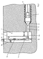
- a beating Horizontalvortriebs réelle 1 with a bursting head 2 is connected via a cable 3 with a vertically arranged in a drill hole cable pulling device 4.
- the cable 3 is attached to the top of the bursting head 2 and guided over a pulley 10 of the cable pulling device 4 through the pit 7 vertically to a reel 8 to the earth's surface.
- the cable pulling device 4 is secured with supports 9 against the pit wall.
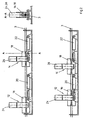
- the traction device 4 has independent traction means 12, 14 which engage by means of clamping jaws 16,18 on the rope.
- the jaws can be moved by hydraulic cylinders 24, 26. Alternatively, they can be operated mechanically on the principle of a winch.
- the traction means 12, 14 have cylinders 20, 22, with the aid of a linear feed of the rope 3 via jaws 16, 18 is possible.
- a controller (not shown)
- the hydraulic cylinders 20, 22 alternately pressurized, so that the respective no pulling force cylinder performs a Re Monthionshub while the rope is moved by the respective other cylinder. Accordingly, the cylinders 24, 26 are acted upon for releasing and clamping the cable 3 alternately.
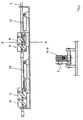
- the traction means 12, 14 may also be designed according to the invention as rod sections 3, which are connected to a linkage and are dismantled individually when pulling. For this purpose, especially in the German Offenlegungsschrift 199 22 813 mentioned conductor linkage advantageous.
- the drive is then also in the German Offenlegungsschrift 198 49 611 described Y-jack drive, in particular with a ladder linkage.
- pushing means the device described can be used in a corresponding manner, in particular with a linkage.
- the pushing means 112, 114 have cylinders 120, 122 and are designed as Y-latches 116, 118 to move the conductor linkage 103.
- the control of the push / pull cylinder is preferably coupled via the operating medium, so that the cylinder movement is zwangsssynchroninstrument.
Landscapes
- Engineering & Computer Science (AREA)
- Geology (AREA)
- Life Sciences & Earth Sciences (AREA)
- Mining & Mineral Resources (AREA)
- Environmental & Geological Engineering (AREA)
- Fluid Mechanics (AREA)
- Physics & Mathematics (AREA)
- General Life Sciences & Earth Sciences (AREA)
- Geochemistry & Mineralogy (AREA)
- Mechanical Engineering (AREA)
- General Engineering & Computer Science (AREA)
- Earth Drilling (AREA)
- Electric Cable Installation (AREA)
- Tension Adjustment In Filamentary Materials (AREA)
- Excavating Of Shafts Or Tunnels (AREA)
Description
- Die Erfindung betrifft ein Schub- oder Zuggerät für Bohr-, Berst- oder Aufweitvorrichtungen für Horizontalvortriebsarbeiten beispielsweise in einem unterirdischen Kanal und nimmt die Priorität der
deutschen Patentanmeldungen 199 58 003.0 und100 11 994.8-24 in Anspruch, auf die inhaltlich Bezug genommen wird. - Ein solcher Kanal kann beispielsweise in Form einer Pilotbohrung erstellt werden oder in Form einer zu ersetzenden unterirdischen Altleitung vorliegen. Das Erstellen einer solchen Pilotbohrung ist in der
deutschen Offenlegungsschrift 197 05 346 beschrieben. - Das zerstörende Ersetzen einer unterirdischen Altleitung ist zum Beispiel in der
deutschen Patentschrift 197 47 250 beschrieben. Beim Erstellen oder Aufweiten der vorgenannten Pilotbohrungen oder dem Erneuern von Altleitungen oder auch dem Einziehen einer neuen Leitung in die Pilotbohrung sind verschiedene Systeme für den Vortrieb der Bohr-, Berst- oder Aufweitvorrichtung, mit deren Hilfe die Pilotbohrung erstellt und in ihrem Querschnitt erweitert oder die Altleitung, beispielsweise durch einen Schneidkopf zerstört wird, bekannt. Unter anderem sind, wie in derdeutschen Patentschrift 195 48 835 beschrieben, dynamisch schlagende Schlagvortriebsgeräte ebenso, wie die in derdeutschen Patentschrift 197 25 628 beschriebenen Geräte mit statischem Vortrieb mittels eines Zug- oder Schubgestänges, bekannt. - Ebenfalls anzutreffen ist die Kombination eines dynamisch arbeitenden Schlagvortriebsgerätes mit einer zusätzlichen Zugvorrichtung, beispielsweise in Form einer Seilwinde. Der Hauptanteil der Vortriebsarbeit wird dabei durch den dynamisch schlagenden Antrieb geleistet, während die Winde in erster Linie zur Führung des Schlagvortriebsgerätes eingesetzt wird. Bei einer solchen Kombination entstehen in der Praxis jedoch erhebliche Probleme, da die Winde unter den dynamischen Schlagkräften des Schlagvortriebsgerätes stark beansprucht wird und insbesondere Schäden an den Trägem des Spillkopfes auftreten.
- Ein weiteres Problem besteht darin, eine konstante Zugkraft mittels einer Winde auf das dynamisch fortschreitende Schlagvortriebsgerät zu übertragen. Dies ist besonders schwierig, in Fällen, in denen das Schiagvortriebsgerät aufgrund eines hohen Umgebungswiderstandes einen äußerst langsamen Vortrieb ausführt und - sofern die Winde keine hierfür besonders eingerichtete Steuerung aufweist - zu einer Überbeanspruchung des Hydraulikantriebs der Winde führen kann.
- Die vorgenannten Probleme werden im Bereich des Schlagbohrens dadurch verstärkt, daß die Entwicklung der dynamischen Schlagvortriebsgeräte von zunehmender Größe gekennzeichnet ist, während entsprechende Winden kaum zur Verfügung stehen. Größere Schlagvortriebsgeräte setzen die Winden einer besonderen Beanspruchung aus, da solchen Geräte eine relativ verringerte Mantelreibung bei extremem Wechsel von Be- und Entlastung zu eigen ist.
- Soweit größere Winden im Stande der Technik bekannt sind, ist deren Anschaffung aufgrund des im Verhältnis zum Schlagvortriebsgerät hohen Anschaffungspreises unwirtschaftlich. Der Versuch, zu klein dimensionierte Winden mit den üblichen Schlagvortriebsgeräten einzusetzen, führt regelmäßig zu einer Beschädigung der Winde.
- Aus der
deutschen Patentschrift 196 08 056 ist eine Vorrichtung zum Verbinden eines Rohrstranges mit einem Spannrahmen und einem linearen Spannantrieb bekannt, die über ein Zugmittel, wie beispielsweise eine Kette, eine Zugkraft zum Verbinden von einzelnen Rohren hinter dem Horizontalvortriebsgerät erzeugt. Eine derartige Vorrichtung wurde in der Praxis auch für den Vortrieb eines Erdvortriebsgerätes eingesetzt und dabei am Vortriebskopf des Gerätes befestigt. Die Verwendung einer Vorrichtung gemäß derdeutschen Patentschrift 196 08 056 für den ergänzenden und leitenden Vortrieb von schlagenden Horizonalvortriebsgeräten verringert zwar bei entsprechender Ausgestaltung die im Stande der Technik von Spillwinden her bekannten Materialprobleme, führt aber zu eigenen Schwierigkeiten aufgrund der nicht kontinuierlich wirkenden Zugkraft. - Zu gleichen Problemen führen die im Stande der Technik bekannten Seilzugvorrichtungen, die insbesondere als Handseilzug bekannt sind, aber auch hydraulisch betrieben werden können. Sämtliche solcher Vorrichtungen weisen einen diskontinuierlichen Seilzug auf, da der Linearantrieb in der Leerhubphase lediglich eine Arretierung des Seils zuläßt und dabei den Seilvortrieb unterbricht. Solche Vorrichtungen eignen sich daher in der Praxis nicht als Windenersatz.
- Des weiteren ist es bekannt, Berst-, Aufweit- oder Bohrgeräte mit Hilfe eines Schub- oder Zuggestänges durch das Erdreich oder durch ein Rohr zu bewegen. Eine entsprechende Vorrichtung ist aus der
deutschen Offenlegungsschrift 197 25 628 bekannt. Auch hierbei ist eine diskontinuierliche Bewegung von Nachteil, da diese nicht nur den Vortrieb erschwert, sondern auch verlangsamt. - Aus der
französischen Offenlegungsschrift 2 592 129 - Der Erfindung liegt nun die Aufgabe zugrunde, eine Schub- oder Zugvorrichtung für ein Horizontalvortriebsgerät zu schaffen, welche die Nachteile herkömmlicher Geräte beim Einsatz mit unterirdischen Horizontalvortriebsgeräten vermeidet.
- Die Aufgabe wird gelöst durch den Gegenstand der unabhängigen Ansprüche. Vorteilhafte Ausführungsformen sind in den Unteransprüchen wiedergegeben.
- Im einzelnen kann die erfindungsgemäße Aufgabe durch die Merkmale des Anspruchs 1 gelöst werden.
- Die erfindungsgemäße Vorrichtung erlaubt es im Bereich der Zugmittel, die Vorteile der kostengünstigen und stabilen Linearantriebe mit den Vorteilen des kontinuierlichen Seilzugs einer Spillwinde zu verbinden. Erfindungsgemäß lassen sich auch mehr als zwei Zugeinheiten einsetzen.
- Mit der erfindungsgemäßen Vorrichtung läßt sich eine weitgehend kontinuierliche Bewegung des Bohrgerätes mit einer Vorrichtung in kompakter Bauweise erreichen, die den auf der Baustelle gewünschten geringen Platzbedarf bei leichter Transportabilität aufweist.
- Die Erfindung wird im folgenden anhand eines in der Zeichnung dargestellten Ausführungsbeispiels des näheren erläutert.
- In der Zeichnung zeigen:
-
Fig. 1 eine schematische Darstellung einer Zugvorrichtung in vertikaler Anordnung; -
Fig. 2 eine Detailansicht der erfindungsgemäßen Vorrichtung derFig. 1 ; -
Fig. 3 eine alternative Ausführungsform einer Zugvorrichtung; -
Fig. 4 eine Ausführungsform entsprechend derFig. 3 mit Gestängeschüssen; -
Fig. 5 eine Ausführungsform mit Y-Klinkenantrieb. - Ein schlagendes Horizontalvortriebsgerät 1 mit einem Berstkopf 2 ist über ein Seil 3 mit einer vertikal in einer Bohrgrube angeordneten Seilzugvorrichtung 4 verbunden. Beim Vortrieb des Berstgerätes 1, 2 wird die im Erdreich befindliche Altleitung 5 zerstört und durch eine neue Leitung 6 ersetzt. Das Seil 3 ist an der Spitze des Berstkopfes 2 befestigt und über eine Umlenkrolle 10 der Seilzugvorrichtung 4 durch die Grube 7 vertikal zu einer Haspel 8 an die Erdoberfläche geführt. Die Seilzugvorrichtung 4 ist mit Stützen 9 gegen die Grubenwand gesichert.
- Die Zugvorrichtung 4 weist unabhängige Zugmittel 12, 14 auf, die mittels Klemmbacken 16,18 an dem Seil angreifen.
- Die Klemmbacken können durch hydraulische Zylinder 24, 26 bewegbar sein. Alternativ können sie mechanisch nach dem Prinzip einer Haspelwinde betrieben sein.
- Die Zugmittel 12, 14 besitzen Zylinder 20, 22, mit deren Hilfe ein linearer Vorschub des Seils 3 über Klemmbacken 16, 18 möglich ist. Über eine Steuerung (nicht dargestellt) werden die hydraulischen Zylinder 20, 22 wechselweise mit Druck beaufschlagt, so daß der jeweils keine Zugkraft ausübende Zylinder einen Retraktionshub ausführt, während das Seil durch den jeweils anderen Zylinder bewegt wird. Entsprechend werden die Zylinder 24, 26 zum Lösen und Klemmen des Seils 3 wechselweise beaufschlagt.
- Die Zugmittel 12, 14 können erfindungsgemäß auch als Gestängeschüsse 3 ausgebildet sein, die zu einem Gestänge verbunden sind und beim Ziehen einzeln abgebaut werden. Hierfür sind insbesondere die in der
deutschen Offenlegungsschrift 199 22 813 erwähnten Leitergestänge vorteilhaft. Als Antrieb eignet sich dann auch der in derdeutschen Offenlegungsschrift 198 49 611 beschriebene Y-Klinkenantrieb, insbesondere mit einem Leitergestänge. Als Schubmittel läßt sich die beschriebene Vorrichtung in entsprechender Weise, insbesondere mit einem Gestänge einsetzen. Hierbei besitzen die Schubmittel 112,114 Zylinder 120, 122 und sind als Y-Klinken 116, 118 ausgebildet, um das Leitergestänge 103 zu bewegen. Die Ansteuerung der Schub/Zugzylinder ist vorzugsweise über das Betriebsmedium gekoppelt, so daß die Zylinderbewegung zwangssynchronisiert ist.
Claims (10)
- Schub- oder Zugvorrichtung für eine horizontale Bohr-, Berst- oder Aufweitvorrichtung mit mindestens einem als Gestänge (3) ausgebildeten Schub- oder Zugmittel zur Verbindung mit der Bohr-, Berst- oder Aufweitvorrichtung, dadurch gekennzeichnet, daß mindestens zwei Schub- oder Zugelemente (12, 13) zur Bewegung des Gestänges (3) einander abwechselnd eine Schub- oder Zugkraft auf das Gestänge (3) ausüben, wodurch eine kontinuierliche Vortriebsbewegung des Gestänges (3) ermöglicht wird.
- Schub- oder Zugvorrichtung nach Anspruch 1, dadurch gekennzeichnet, daß das Gestänge aus miteinander gekuppelten Gestängeschüssen (3) besteht.
- Schub- oder Zugvorrichtung nach einem der vorhergehenden Ansprüche, dadurch gekennzeichnet, daß die Schub- oder Zugelemente (12, 14) als hydraulisch beaufschlagte Zylinder ausgebildet sind.
- Schub- oder Zugvorrichtung nach einem der vorhergehenden Ansprüche, dadurch gekennzeichnet, daß die Schub- oder Zugkraft über mechanisch durch Schub oder Zug verriegelnde Klemmbacken (16, 18) auf das Gestänge (3) übertragen wird.
- Schub- oder Zugvorrichtung nach Anspruch 3, dadurch gekennzeichnet, daß die Schub- oder Zugkraft über ein Leitergestänge mit Y-Klinken (116, 118) übertragen wird.
- Schub- oder Zugvorrichtung nach Anspruch 3, dadurch gekennzeichnet, daß die Zylinder (20, 22) synchronisiert sind.
- Verfahren zum Betrieb einer Zugvorrichtung nach einem der vorhergehende Ansprüche, dadurch gekennzeichnet, daß die Zugvorrichtung auf ein vertikal geführtes Gestänge (3) einwirkt und in einer Zielgrube (7) betrieben wird.
- Horizontalvortriebsgerät mit einem angelenkten Gestänge (3) und einer auf das Gestänge (3) wirkenden Schub- oder Zugvorrichtung nach einem der Ansprüche 1 bis 6.
- Verfahren zum Erzeugen einer Aufweitbohrung oder Sanierung einer Altleitung mit einem schlagenden Horizontalvortriebsgerät nach Anspruch 8, dadurch gekennzeichnet, daß das Horizontalvortriebsgerät an einem Gestänge (3) durch eine Pilotbohrung/Altleitung (5) geführt wird und das Gestänge (3) über einen Linearantrieb (12, 14) kontinuierlich bewegt wird.
- Verfahren nach Anspruch 9, dadurch gekennzeichnet, daß die kontinuierliche Bewegung über Gestängeschüsse, die zu dem Gestänge verbunden sind, bewirkt wird.
Applications Claiming Priority (5)
| Application Number | Priority Date | Filing Date | Title |
|---|---|---|---|
| DE19958003 | 1999-12-02 | ||
| DE19958003 | 1999-12-02 | ||
| DE10011994 | 2000-03-11 | ||
| DE10011994A DE10011994C1 (de) | 1999-12-02 | 2000-03-11 | Seilzugvorrichtung für Berst-/Aufweitvorrichtungen |
| PCT/EP2000/011848 WO2001040699A1 (de) | 1999-12-02 | 2000-11-28 | Seilzugvorrichtung für berst-/aufweitvorrichtungen |
Publications (3)
| Publication Number | Publication Date |
|---|---|
| EP1236005A1 EP1236005A1 (de) | 2002-09-04 |
| EP1236005B1 EP1236005B1 (de) | 2004-04-28 |
| EP1236005B2 true EP1236005B2 (de) | 2012-02-01 |
Family
ID=26004807
Family Applications (1)
| Application Number | Title | Priority Date | Filing Date |
|---|---|---|---|
| EP00977589A Expired - Lifetime EP1236005B2 (de) | 1999-12-02 | 2000-11-28 | Seilzugvorrichtung für berst-/aufweitvorrichtungen |
Country Status (4)
| Country | Link |
|---|---|
| EP (1) | EP1236005B2 (de) |
| AT (1) | ATE265649T1 (de) |
| AU (1) | AU773656B2 (de) |
| WO (1) | WO2001040699A1 (de) |
Families Citing this family (2)
| Publication number | Priority date | Publication date | Assignee | Title |
|---|---|---|---|---|
| DE10302194B3 (de) * | 2003-01-20 | 2004-08-19 | Tracto-Technik Gmbh | Vorrichtung und Verfahren zum Einziehen einer Leitung oder eines Bohrwerkzeugs in einen Kanal |
| GB0512521D0 (en) * | 2005-06-21 | 2005-07-27 | Scott Kenneth L | Apparatus for use in renewing or replacing drain pipes or service ducts |
Citations (2)
| Publication number | Priority date | Publication date | Assignee | Title |
|---|---|---|---|---|
| US4615509A (en) † | 1985-10-23 | 1986-10-07 | Cibeles International Inc. | Continuous operation linear hydraulic winch |
| US4983071A (en) † | 1990-05-15 | 1991-01-08 | Consolidated Edison Company Of New York, Inc. | Pipe bursting and replacement apparatus and method |
Family Cites Families (9)
| Publication number | Priority date | Publication date | Assignee | Title |
|---|---|---|---|---|
| FR2592129B1 (fr) * | 1985-12-20 | 1990-06-15 | Virax Sa | Pousse-tube automoteur |
| DE19608056C1 (de) | 1996-03-02 | 1997-10-30 | Tracto Technik | Vorrichtung zum Verbinden eines Rohrstranges mit einem Gerät zum Erstellen von Erdbohrungen |
| DE19705346C1 (de) | 1997-02-12 | 1999-01-28 | Thomas Dipl Ing Loeffler | Verfahren und Vorrichtung zum Herstellen von Schraubverbindungen |
| DE19725628C1 (de) | 1997-06-17 | 1999-03-04 | Tracto Technik | Bohrvorrichtung |
| DE19747250C1 (de) | 1997-10-25 | 1999-01-14 | Tracto Technik | Verbindungsstück zum Einziehen von Rohrleitungen |
| DE19849611C1 (de) * | 1998-10-28 | 2000-03-09 | Tracto Technik | Vorrichtung zum statischen Erdbohren |
| DE59912193D1 (de) * | 1998-03-30 | 2005-07-28 | Wolfgang Schmidt E K | Vorrichtung zum statischen Erdbohren |
| DE19819611C2 (de) | 1998-05-04 | 2000-07-06 | Brose Fahrzeugteile | Verfahren zur Ansteuerung von elektromotorisch betätigten Schlössern, insbesondere in Kraftfahrzeugtüren |
| DE19922813C2 (de) | 1999-02-23 | 2001-03-29 | Tracto Technik | Automatisches Gestänge |
-
2000
- 2000-11-28 AU AU15246/01A patent/AU773656B2/en not_active Ceased
- 2000-11-28 AT AT00977589T patent/ATE265649T1/de not_active IP Right Cessation
- 2000-11-28 WO PCT/EP2000/011848 patent/WO2001040699A1/de not_active Ceased
- 2000-11-28 EP EP00977589A patent/EP1236005B2/de not_active Expired - Lifetime
Patent Citations (2)
| Publication number | Priority date | Publication date | Assignee | Title |
|---|---|---|---|---|
| US4615509A (en) † | 1985-10-23 | 1986-10-07 | Cibeles International Inc. | Continuous operation linear hydraulic winch |
| US4983071A (en) † | 1990-05-15 | 1991-01-08 | Consolidated Edison Company Of New York, Inc. | Pipe bursting and replacement apparatus and method |
Also Published As
| Publication number | Publication date |
|---|---|
| EP1236005B1 (de) | 2004-04-28 |
| EP1236005A1 (de) | 2002-09-04 |
| ATE265649T1 (de) | 2004-05-15 |
| AU1524601A (en) | 2001-06-12 |
| WO2001040699A1 (de) | 2001-06-07 |
| AU773656B2 (en) | 2004-06-03 |
Similar Documents
| Publication | Publication Date | Title |
|---|---|---|
| EP2067924B1 (de) | Bohranlage und Bohrverfahren | |
| EP0794315B1 (de) | Vorrichtung zum Bohren im Erdreich | |
| EP2430284B1 (de) | Zug- und druckvorrichtung | |
| EP2553202B1 (de) | Verfahren zum betrieb einer horizontalbohrvorrichtung und horizontalbohrvorrichtung | |
| EP2728104A1 (de) | Verfahren zum Erstellen einer Horizontalbohrung im Erdreich und Horizontalbohrvorrichtung | |
| EP2304179B1 (de) | Automatisiertes bohr- und ankersetzgerät mit separaten lafetten | |
| EP2322724A1 (de) | Unterwasserbohranordnung und Verfahren zum Einbringen eines rohrförmigen Gründungselements in den Gewässergrund | |
| DE10011994C1 (de) | Seilzugvorrichtung für Berst-/Aufweitvorrichtungen | |
| EP1236005B2 (de) | Seilzugvorrichtung für berst-/aufweitvorrichtungen | |
| DE3903864C1 (en) | Method and apparatus for redeveloping old pipes | |
| EP2447462A1 (de) | Verfahren zum unterirdischen Einbringen einer Rohrleitung | |
| DE3612762A1 (de) | Teleskopierbares bohrgeraet | |
| DE10146024A1 (de) | Schlagwerk für eine Erdbohrvorrichtung | |
| EP2626506B1 (de) | Vorrichtung zum Bewegen eines Arbeitsmittels im Erdreich | |
| EP1407112B1 (de) | Verfahren zum herstellen von erdbohrungen | |
| WO2003004823A1 (de) | Seilzugvorrichtung zum einziehen von rohren | |
| DE3729560A1 (de) | Verfahren und vorrichtung zur herstellung einer rohrleitung in einer im erdreich ausgebildeten durchbohrung | |
| DE10302194B3 (de) | Vorrichtung und Verfahren zum Einziehen einer Leitung oder eines Bohrwerkzeugs in einen Kanal | |
| DE10211833A1 (de) | Vorrichtung zum grabenlosen Austauschen von Leitungen | |
| DE10125869C2 (de) | Seilzugvorrichtung und Verfahren | |
| DE19529554C2 (de) | Bohr- und/oder Injektionsvorrichtung | |
| EP3029263B1 (de) | Horizontalerdbohrvorrichtung | |
| DE10163643C1 (de) | Verfahren und Vorrichtung zum zerstörenden Einbringen eines Neurohrs in eine Trasse | |
| EP3431702B1 (de) | Verfahren und vorrichtung zur grabenlosen verlegung eines kabels oder rohres in einem boden | |
| DE19962298A1 (de) | Einpressvorrichtung für Rohre und Rohrgestänge |
Legal Events
| Date | Code | Title | Description |
|---|---|---|---|
| PUAI | Public reference made under article 153(3) epc to a published international application that has entered the european phase |
Free format text: ORIGINAL CODE: 0009012 |
|
| 17P | Request for examination filed |
Effective date: 20020625 |
|
| AK | Designated contracting states |
Kind code of ref document: A1 Designated state(s): AT BE CH CY DE DK ES FI FR GB GR IE IT LI LU MC NL PT SE TR |
|
| AX | Request for extension of the european patent |
Free format text: AL;LT;LV;MK;RO;SI |
|
| 17Q | First examination report despatched |
Effective date: 20030512 |
|
| GRAP | Despatch of communication of intention to grant a patent |
Free format text: ORIGINAL CODE: EPIDOSNIGR1 |
|
| GRAS | Grant fee paid |
Free format text: ORIGINAL CODE: EPIDOSNIGR3 |
|
| GRAA | (expected) grant |
Free format text: ORIGINAL CODE: 0009210 |
|
| AK | Designated contracting states |
Kind code of ref document: B1 Designated state(s): AT BE CH CY DE DK ES FI FR GB GR IE IT LI LU MC NL PT SE TR |
|
| PG25 | Lapsed in a contracting state [announced via postgrant information from national office to epo] |
Ref country code: IT Free format text: LAPSE BECAUSE OF FAILURE TO SUBMIT A TRANSLATION OF THE DESCRIPTION OR TO PAY THE FEE WITHIN THE PRESCRIBED TIME-LIMIT;WARNING: LAPSES OF ITALIAN PATENTS WITH EFFECTIVE DATE BEFORE 2007 MAY HAVE OCCURRED AT ANY TIME BEFORE 2007. THE CORRECT EFFECTIVE DATE MAY BE DIFFERENT FROM THE ONE RECORDED. Effective date: 20040428 Ref country code: FR Free format text: LAPSE BECAUSE OF FAILURE TO SUBMIT A TRANSLATION OF THE DESCRIPTION OR TO PAY THE FEE WITHIN THE PRESCRIBED TIME-LIMIT Effective date: 20040428 Ref country code: CY Free format text: LAPSE BECAUSE OF FAILURE TO SUBMIT A TRANSLATION OF THE DESCRIPTION OR TO PAY THE FEE WITHIN THE PRESCRIBED TIME-LIMIT Effective date: 20040428 Ref country code: TR Free format text: LAPSE BECAUSE OF FAILURE TO SUBMIT A TRANSLATION OF THE DESCRIPTION OR TO PAY THE FEE WITHIN THE PRESCRIBED TIME-LIMIT Effective date: 20040428 Ref country code: NL Free format text: LAPSE BECAUSE OF FAILURE TO SUBMIT A TRANSLATION OF THE DESCRIPTION OR TO PAY THE FEE WITHIN THE PRESCRIBED TIME-LIMIT Effective date: 20040428 Ref country code: FI Free format text: LAPSE BECAUSE OF FAILURE TO SUBMIT A TRANSLATION OF THE DESCRIPTION OR TO PAY THE FEE WITHIN THE PRESCRIBED TIME-LIMIT Effective date: 20040428 Ref country code: IE Free format text: LAPSE BECAUSE OF FAILURE TO SUBMIT A TRANSLATION OF THE DESCRIPTION OR TO PAY THE FEE WITHIN THE PRESCRIBED TIME-LIMIT Effective date: 20040428 |
|
| REG | Reference to a national code |
Ref country code: GB Ref legal event code: FG4D Free format text: NOT ENGLISH |
|
| REG | Reference to a national code |
Ref country code: CH Ref legal event code: EP |
|
| REG | Reference to a national code |
Ref country code: IE Ref legal event code: FG4D Free format text: GERMAN |
|
| REF | Corresponds to: |
Ref document number: 50006277 Country of ref document: DE Date of ref document: 20040603 Kind code of ref document: P |
|
| GBT | Gb: translation of ep patent filed (gb section 77(6)(a)/1977) |
Effective date: 20040623 |
|
| PG25 | Lapsed in a contracting state [announced via postgrant information from national office to epo] |
Ref country code: DK Free format text: LAPSE BECAUSE OF FAILURE TO SUBMIT A TRANSLATION OF THE DESCRIPTION OR TO PAY THE FEE WITHIN THE PRESCRIBED TIME-LIMIT Effective date: 20040728 Ref country code: SE Free format text: LAPSE BECAUSE OF FAILURE TO SUBMIT A TRANSLATION OF THE DESCRIPTION OR TO PAY THE FEE WITHIN THE PRESCRIBED TIME-LIMIT Effective date: 20040728 Ref country code: GR Free format text: LAPSE BECAUSE OF FAILURE TO SUBMIT A TRANSLATION OF THE DESCRIPTION OR TO PAY THE FEE WITHIN THE PRESCRIBED TIME-LIMIT Effective date: 20040728 |
|
| PG25 | Lapsed in a contracting state [announced via postgrant information from national office to epo] |
Ref country code: ES Free format text: LAPSE BECAUSE OF FAILURE TO SUBMIT A TRANSLATION OF THE DESCRIPTION OR TO PAY THE FEE WITHIN THE PRESCRIBED TIME-LIMIT Effective date: 20040808 |
|
| NLV1 | Nl: lapsed or annulled due to failure to fulfill the requirements of art. 29p and 29m of the patents act | ||
| LTIE | Lt: invalidation of european patent or patent extension |
Effective date: 20040428 |
|
| PG25 | Lapsed in a contracting state [announced via postgrant information from national office to epo] |
Ref country code: AT Free format text: LAPSE BECAUSE OF NON-PAYMENT OF DUE FEES Effective date: 20041128 Ref country code: LU Free format text: LAPSE BECAUSE OF NON-PAYMENT OF DUE FEES Effective date: 20041128 |
|
| PG25 | Lapsed in a contracting state [announced via postgrant information from national office to epo] |
Ref country code: LI Free format text: LAPSE BECAUSE OF NON-PAYMENT OF DUE FEES Effective date: 20041130 Ref country code: CH Free format text: LAPSE BECAUSE OF NON-PAYMENT OF DUE FEES Effective date: 20041130 Ref country code: MC Free format text: LAPSE BECAUSE OF NON-PAYMENT OF DUE FEES Effective date: 20041130 Ref country code: BE Free format text: LAPSE BECAUSE OF NON-PAYMENT OF DUE FEES Effective date: 20041130 |
|
| REG | Reference to a national code |
Ref country code: IE Ref legal event code: FD4D |
|
| PLBQ | Unpublished change to opponent data |
Free format text: ORIGINAL CODE: EPIDOS OPPO |
|
| PLBI | Opposition filed |
Free format text: ORIGINAL CODE: 0009260 |
|
| PLAX | Notice of opposition and request to file observation + time limit sent |
Free format text: ORIGINAL CODE: EPIDOSNOBS2 |
|
| 26 | Opposition filed |
Opponent name: TERRA AG FUER TIEFBAUTECHNIK Effective date: 20050128 |
|
| EN | Fr: translation not filed | ||
| BERE | Be: lapsed |
Owner name: *TRACTO-TECHNIK G.M.B.H. Effective date: 20041130 |
|
| PLAF | Information modified related to communication of a notice of opposition and request to file observations + time limit |
Free format text: ORIGINAL CODE: EPIDOSCOBS2 |
|
| REG | Reference to a national code |
Ref country code: CH Ref legal event code: PL |
|
| PLBB | Reply of patent proprietor to notice(s) of opposition received |
Free format text: ORIGINAL CODE: EPIDOSNOBS3 |
|
| BERE | Be: lapsed |
Owner name: *TRACTO-TECHNIK G.M.B.H. Effective date: 20041130 |
|
| PG25 | Lapsed in a contracting state [announced via postgrant information from national office to epo] |
Ref country code: PT Free format text: LAPSE BECAUSE OF NON-PAYMENT OF DUE FEES Effective date: 20040928 |
|
| PLAY | Examination report in opposition despatched + time limit |
Free format text: ORIGINAL CODE: EPIDOSNORE2 |
|
| PLBC | Reply to examination report in opposition received |
Free format text: ORIGINAL CODE: EPIDOSNORE3 |
|
| PUAH | Patent maintained in amended form |
Free format text: ORIGINAL CODE: 0009272 |
|
| STAA | Information on the status of an ep patent application or granted ep patent |
Free format text: STATUS: PATENT MAINTAINED AS AMENDED |
|
| 27A | Patent maintained in amended form |
Effective date: 20120201 |
|
| AK | Designated contracting states |
Kind code of ref document: B2 Designated state(s): AT BE CH CY DE DK ES FI FR GB GR IE IT LI LU MC NL PT SE TR |
|
| REG | Reference to a national code |
Ref country code: DE Ref legal event code: R102 Ref document number: 50006277 Country of ref document: DE |
|
| REG | Reference to a national code |
Ref country code: DE Ref legal event code: R102 Ref document number: 50006277 Country of ref document: DE Effective date: 20120201 |
|
| PGFP | Annual fee paid to national office [announced via postgrant information from national office to epo] |
Ref country code: GB Payment date: 20141120 Year of fee payment: 15 |
|
| GBPC | Gb: european patent ceased through non-payment of renewal fee |
Effective date: 20151128 |
|
| PG25 | Lapsed in a contracting state [announced via postgrant information from national office to epo] |
Ref country code: GB Free format text: LAPSE BECAUSE OF NON-PAYMENT OF DUE FEES Effective date: 20151128 |
|
| PGFP | Annual fee paid to national office [announced via postgrant information from national office to epo] |
Ref country code: DE Payment date: 20161220 Year of fee payment: 17 |
|
| REG | Reference to a national code |
Ref country code: DE Ref legal event code: R119 Ref document number: 50006277 Country of ref document: DE |
|
| PG25 | Lapsed in a contracting state [announced via postgrant information from national office to epo] |
Ref country code: DE Free format text: LAPSE BECAUSE OF NON-PAYMENT OF DUE FEES Effective date: 20180602 |