EP1235508B1 - Wavefront sensor with off-axis illumination - Google Patents
Wavefront sensor with off-axis illumination Download PDFInfo
- Publication number
- EP1235508B1 EP1235508B1 EP00976606A EP00976606A EP1235508B1 EP 1235508 B1 EP1235508 B1 EP 1235508B1 EP 00976606 A EP00976606 A EP 00976606A EP 00976606 A EP00976606 A EP 00976606A EP 1235508 B1 EP1235508 B1 EP 1235508B1
- Authority
- EP
- European Patent Office
- Prior art keywords
- light
- eye
- retina
- beamsplitter
- reflected
- Prior art date
- Legal status (The legal status is an assumption and is not a legal conclusion. Google has not performed a legal analysis and makes no representation as to the accuracy of the status listed.)
- Expired - Lifetime
Links
- 238000005286 illumination Methods 0.000 title description 7
- 210000001525 retina Anatomy 0.000 claims description 37
- 230000003287 optical effect Effects 0.000 claims description 36
- 230000004075 alteration Effects 0.000 claims description 13
- 210000004087 cornea Anatomy 0.000 claims description 13
- 210000001747 pupil Anatomy 0.000 claims description 6
- 230000000903 blocking effect Effects 0.000 claims description 2
- 238000000926 separation method Methods 0.000 claims 1
- 238000000034 method Methods 0.000 description 14
- 230000002207 retinal effect Effects 0.000 description 6
- 230000007246 mechanism Effects 0.000 description 5
- 238000001514 detection method Methods 0.000 description 3
- 238000006073 displacement reaction Methods 0.000 description 3
- 238000001356 surgical procedure Methods 0.000 description 3
- 230000008901 benefit Effects 0.000 description 2
- 238000010586 diagram Methods 0.000 description 2
- 230000000694 effects Effects 0.000 description 2
- 238000003384 imaging method Methods 0.000 description 2
- 230000006872 improvement Effects 0.000 description 2
- 238000004519 manufacturing process Methods 0.000 description 2
- 238000005259 measurement Methods 0.000 description 2
- 230000010287 polarization Effects 0.000 description 2
- 206010033799 Paralysis Diseases 0.000 description 1
- 230000004308 accommodation Effects 0.000 description 1
- 230000003044 adaptive effect Effects 0.000 description 1
- 230000005540 biological transmission Effects 0.000 description 1
- 230000008859 change Effects 0.000 description 1
- 230000008878 coupling Effects 0.000 description 1
- 238000010168 coupling process Methods 0.000 description 1
- 238000005859 coupling reaction Methods 0.000 description 1
- 230000002939 deleterious effect Effects 0.000 description 1
- 230000002040 relaxant effect Effects 0.000 description 1
- 230000004256 retinal image Effects 0.000 description 1
- 238000002834 transmittance Methods 0.000 description 1
Images
Classifications
-
- A—HUMAN NECESSITIES
- A61—MEDICAL OR VETERINARY SCIENCE; HYGIENE
- A61B—DIAGNOSIS; SURGERY; IDENTIFICATION
- A61B3/00—Apparatus for testing the eyes; Instruments for examining the eyes
- A61B3/10—Objective types, i.e. instruments for examining the eyes independent of the patients' perceptions or reactions
- A61B3/14—Arrangements specially adapted for eye photography
- A61B3/15—Arrangements specially adapted for eye photography with means for aligning, spacing or blocking spurious reflection ; with means for relaxing
- A61B3/156—Arrangements specially adapted for eye photography with means for aligning, spacing or blocking spurious reflection ; with means for relaxing for blocking
-
- G—PHYSICS
- G01—MEASURING; TESTING
- G01J—MEASUREMENT OF INTENSITY, VELOCITY, SPECTRAL CONTENT, POLARISATION, PHASE OR PULSE CHARACTERISTICS OF INFRARED, VISIBLE OR ULTRAVIOLET LIGHT; COLORIMETRY; RADIATION PYROMETRY
- G01J9/00—Measuring optical phase difference; Determining degree of coherence; Measuring optical wavelength
Definitions
- the present invention is directed to a wavefront sensor, such as a sensor for wavefront aberrations in the eye, and more particularly to such a sensor which avoids corneal reflection by illuminating the retina along a light path off of the optical axis of the eye.
- the present invention is further directed to a method of sensing a wavefront using such off-axis illumination.
- the emergent beam is applied to a Hartmann-Shack detector to detect the aberrations.
- a detector includes an array of lenslets which break up the light into an array of spots and focus the spots onto a charge-coupled detector or other two-dimensional light detector.
- Each spot is located to determine its displacement from the position which it would occupy in the absence of wavefront aberrations, and the displacements of the spots allow reconstruction of the wavefront and thus detection of the aberrations.
- the techniques described above involve illuminating the eye along the eye's optical axis. As a consequence, the light reflected from the retina is mixed with stray reflections which can disrupt measurements. More specifically, the stray reflections show up as spurious bright spots amid the array of spots formed in the Hartmann-Shack sensor.
- Such stray reflections have several sources in wavefront sensors. Of particular concern are the reflections from the optical elements between the retina and the beamsplitter. Such elements typically include the optics of the eye and a pair of lenses between the beamsplitter and the eye. Back reflections from surfaces other than the retina are weak relative to the illuminating beam but are bright relative to the weak signal reflected from the retina.
- the only surface whose back reflection is bright enough to be problematic is the first (outer) surface of the cornea. That reflection is comparable in energy to the reflection from the retina and can therefore be a considerable nuisance for wavefront sensing, particularly if the centroids of the spots in the detector are to be computed automatically.
- German published patent application No. DE 42 22 395 A1 teaches that technique. That technique allows a much greater part of the light reflected from the retina to reach the detector, thereby improving spot quality, while removing the variation in spot brightness caused by the birefringence of the eye. It also removes back reflection from the lenses. However, the corneal reflection is not removed and is thus just as troublesome as it would be in the absence of polarizing optics.
- Another problem with the two techniques just described is the cost of the polarizing beamsplitter and of the ⁇ /4 plate. In cost-sensitive commercial settings, it would be desirable to eliminate that cost.
- EP 0691103 teaches a technique for fundus imaging using off-axis illumination. However, there is no suggestion to use that technique in the detection of wavefront aberrations as described in the above-noted prior art.
- the present invention is directed to a wavefront sensor in which the eye is illuminated off-axis.
- the light not reflected by the cornea impinges on the retina, and the light reflected by the retina returns through the lens and the cornea. That light is thereby focussed into an optical path different from the optical path followed by the corneal reflection.
- the entire retinal reflection is used, and the corneal reflection can be discarded by use of simple, inexpensive, non-polarizing optics such as a stop.
- the beam used to illuminate the eye is relatively narrow, e.g. around 1-1.5 mm in diameter, and intersects the cornea in a small area, thus further reducing the probability that the corneal reflection will take a return path to the detector.
- the dioptric range over which the small spot is in focus on the retina can be increased.
- a displacement of the illuminating beam from the optical axis of the eye by less than one millimetre completely removes the corneal reflection.
- the illuminating beam is preferably introduced into the optical path at the last possible location before the eye, e.g., by placing the beamsplitter right before the eye.
- the beamsplitter right before the eye.
- the light source can be moved in a direction perpendicular (or, more generally, non-parallel) to the direction of its output as needed to accommodate the eyes of different patients.
- the present invention has utility in any procedure involving wavefront sensing of the eye or otherwise involving illumination of the retina.
- Such procedures include, but are not limited to, autorefraction, design of contract or intraocular lenses, refractive surgery and retinal imaging with adaptive optics. While it is contemplated that the present invention will be used with the human eye, veterinary or even non-eye-related applications can be developed as well.
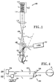
- Fig. 1 shows an overview of a basic system 100 for illuminating the retina of the patient's eye E and will be used to explain the optical principles implemented in the preferred embodiment.
- a laser light source 102 such as a laser diode, emits a beam of light L 1 toward a beamsplitter 104, which can be a parallel-plate beamsplitter, a thick-plate beamsplitter, a prism beamsplitter, a half silvered mirror, or another suitable beamsplitter.
- the beamsplitter 104 is preferably 90% trnasmissive and 10% reflective, although other ratios could be used as needed.
- the laser light source 102 and the beamsplitter 104 are positioned such that the light L 1 impinges on the eye E off of the optical axis A of the eye E.
- a light beam L 2 reflected from the cornea C of the eye E is reflected off of the optical axis A.
- the remaining light forms a laser beacon B on the retina R of the eye E.
- a light beam L 3 reflected from the retina R of the eye E exits the eye E and passes through the beamsplitter 104.
- the light beam L 3 then passes through a lens 106, a stop 108 which passes the light beam L 3 reflected from the retina while blocking the light beam L 2 reflected from the cornea, and a lens 110 to a Hartmann-Shack detector 112.
- the detector 112 includes a lenslet array 114 to focus the light beam L 3 as an array of light spots L 4 onto a CCD or other suitable two-dimensional detector 116.
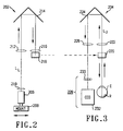
- Figs. 2-4 show a second-generation system 200 using the optical principles just explained with reference to Fig. 1.
- Fig. 2 shows a lower level 202 of the system 200 as seen from above
- Fig. 3 shows an upper level 204 of the system 200 as seen from above
- Fig. 4 shows both levels 202, 204 of the system 200 as seen from the right.
- a laser diode 206 is mounted on a mount 208 for horizontal positioning. The purpose of such positioning will be explained below.
- a light beam emitted from the diode 206 follows a lower-level light path designated generally as L 1. through lenses 210 and 212.
- the light beam is retroreflected by a corner mirror 214 and passes through a lens 216 to a mirror 218 which reflects the light beam upward.
- a parallel-plate beamsplitter 220 receives the light beam reflected upward by the mirror 218 and directs that light beam along an upper-level light path designated generally as L U
- L U The path L U is shown in greatly simplified form; the above discussion of Fig. I will provide those skilled in the art with an understanding of the requirements for the true optical path.
- the light beam illuminates the eye E in the manner explained above with reference to Fig. 1.
- a retinal reflection light beam reflected by the retina R of the eye E travels back through the beamsplitter 220 and a lens 222.
- the retinal reflection light beam is then retroreflected by a corner mirror 224 through a lens 226 to a Hartmann-Shack detector 228 which includes a lenslet array 230 and a CCD detector 232.
- a stop can be included at an appropriate location along the light path L U , e.g., at the focus of the lens 222.
- a single mirror can be used to replace the mirrors 214 and 224.
- the diameter of the incident light beam is a suitable value, e.g., 1.5 mm.
- the small diameter increases the depth of focus on the retina, thus relaxing the requirement to focus the light on the patient accurately.
- the small diameter also ensures that the spot on the retina will be diffraction-limited.
- the entry beam should be no smaller than approximately the diameter of a lenslet in the lenslet array. Otherwise, diffraction in the entering beam will significantly blur the spots on the CCD.
- the entry beam is displaced in the pupil from the corneal pole by a distance of more than one-half the diameter of the beam to separate the corneal and retinal reflections and thereby to avoid the effects of corneal reflection and is preferably displaced by about 1 mm.
- the distance may vary from subject to subject and can be less than 1 mm because of the small entrance beam diameter.
- the distance can be varied with the mount 208, which translates the diode 206 and its collimating optics by a small amount. The ability to translate the diode 206 and its optics by up to 1 mm suffices.
- the reflected light from the cornea is diverged and collimated by the lens 222, so that it can be blocked by a stop placed at the focus of the lens 222 or by another suitable optical element.
- Back reflections from other optical components can be avoided by placing the beamsplitter 220 in the last possible place, just before the eye E. That arrangement allows the illuminating beam to avoid the other optical elements, since the only thing between the beamsplitter 220 and the retina R is the cornea C.
- the usual reflections from the beamsplitter can be avoided by using a rotated beamsplitter cube or a thick-plate beamsplitter. It is not necessary to subtract an image without the eye in place from an image with the eye in place to remove stray light, as was often required in the prior art.
- the optical path length of the system 200 can be varied by coupling the mirrors 214 and 224 to a slide mechanism 234 so that the mirrors 214 and 224 can be moved as a single rigid body.
- the mirrors 214 and 224 are displaced from each other axially.
- the movement of the slide mechanism 234 by a distance x changes the optical path length of each level 202, 204 by a distance 2x and of the system 200 as a whole by a distance 4x.
- a slide mechanism allows the entering beam to be focused on the retina at the same time and with the same device with which the exit beam is focused on the CCD array, namely, the slide 234 bearing the mirrors 214 and 224. Since the mirror 214 is in the path of the illuminating beam before that beam reaches the beamsplitter 220 and the mirror 224 is in the path of the exit beam, movement of the slide 234 changes the path lengths of both beams and thereby allows adjustment of the focus of both beams.
- the slide 234 thus provides economy and convenience.
- Double slide mechanisms could be implemented in the system 200.
- another mirror (not shown) could be placed opposite the mirrors 214 and 224 to cause the light beam to make another pass through the system.
- movement of the slide mechanism 234 by a distance x would change the total optical path length by a distance 8x.
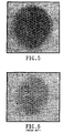
- Figs. 5 and 6 show experimental results in Figs. 5 and 6.
- FIG. 5 A comparison of Figs. 5 and 6 shows that the present invention provides a great improvement in light throughput and also in spot quality.
- the spot pattern shown in Fig. 5 has much better intensity uniformity than that of Fig. 6 and has an average spot intensity four times higher than that of Fig. 6.
- the spot pattern of Fig. 5 is comparable to that obtained with a polarizing beamsplitter and a ⁇ /4 plate, without the drawbacks of that technique.
- the single non-polarizing beamsplitter 220 which can be a parallel plate beamsplitter or the like, is less expensive than the optics required for the polarizing techniques of the prior art, with or without a ⁇ /4 plate.
- the use of a beamsplitter with a ratio of transmittance to reflection greater than one further increases the light available.
- the present invention offers many advantages.
- the deleterious effects of back reflections in the eye and other optics are avoided, thereby making the instrument more robust and the software to operate it simpler.
- the quality of the spot images is not degraded by polarization effects, so that accuracy is improved.
- the throughput is higher than that of the prior art, so that a greater signal can be achieved for the same level of illumination and thus the same level of patient comfort and safety.
- the same signal as in the prior art can be achieved with reduced illuminating light intensity and thus improved patient comfort and safety.
- the ratio of transmission to reflection of the plate beamsplitter can be chosen to transmit almost all of the light from the retina to the CCD array. Since no polarizing optics are required, the cost is reduced.
- the optical path can have additional folds for improved path length and compactness, and a fixation target and pupil camera can be added.
- the light source can be positioned in any manner which spatially separates the retinal and corneal reflections, e.g., by selection of an appropriate angle of incidence. Therefore, the present invention should be construed as limited only by the appended claims.
Landscapes
- Health & Medical Sciences (AREA)
- Life Sciences & Earth Sciences (AREA)
- Physics & Mathematics (AREA)
- Spectroscopy & Molecular Physics (AREA)
- Medical Informatics (AREA)
- Animal Behavior & Ethology (AREA)
- Biomedical Technology (AREA)
- Heart & Thoracic Surgery (AREA)
- Ophthalmology & Optometry (AREA)
- Molecular Biology (AREA)
- Surgery (AREA)
- Engineering & Computer Science (AREA)
- General Health & Medical Sciences (AREA)
- Public Health (AREA)
- Veterinary Medicine (AREA)
- Biophysics (AREA)
- General Physics & Mathematics (AREA)
- Eye Examination Apparatus (AREA)
Priority Applications (2)
| Application Number | Priority Date | Filing Date | Title |
|---|---|---|---|
| EP05008541A EP1561417B1 (en) | 1999-10-21 | 2000-10-20 | Wavefront sensor with off-axis illumination |
| EP05008540A EP1561416B1 (en) | 1999-10-21 | 2000-10-20 | Wavefront sensor with off-axis illumination |
Applications Claiming Priority (3)
| Application Number | Priority Date | Filing Date | Title |
|---|---|---|---|
| US422338 | 1982-09-23 | ||
| US09/422,338 US6264328B1 (en) | 1999-10-21 | 1999-10-21 | Wavefront sensor with off-axis illumination |
| PCT/US2000/029008 WO2001028411A1 (en) | 1999-10-21 | 2000-10-20 | Wavefront sensor with off-axis illumination |
Related Child Applications (2)
| Application Number | Title | Priority Date | Filing Date |
|---|---|---|---|
| EP05008541A Division EP1561417B1 (en) | 1999-10-21 | 2000-10-20 | Wavefront sensor with off-axis illumination |
| EP05008540A Division EP1561416B1 (en) | 1999-10-21 | 2000-10-20 | Wavefront sensor with off-axis illumination |
Publications (2)
| Publication Number | Publication Date |
|---|---|
| EP1235508A1 EP1235508A1 (en) | 2002-09-04 |
| EP1235508B1 true EP1235508B1 (en) | 2006-08-09 |
Family
ID=23674453
Family Applications (3)
| Application Number | Title | Priority Date | Filing Date |
|---|---|---|---|
| EP00976606A Expired - Lifetime EP1235508B1 (en) | 1999-10-21 | 2000-10-20 | Wavefront sensor with off-axis illumination |
| EP05008541A Expired - Lifetime EP1561417B1 (en) | 1999-10-21 | 2000-10-20 | Wavefront sensor with off-axis illumination |
| EP05008540A Expired - Lifetime EP1561416B1 (en) | 1999-10-21 | 2000-10-20 | Wavefront sensor with off-axis illumination |
Family Applications After (2)
| Application Number | Title | Priority Date | Filing Date |
|---|---|---|---|
| EP05008541A Expired - Lifetime EP1561417B1 (en) | 1999-10-21 | 2000-10-20 | Wavefront sensor with off-axis illumination |
| EP05008540A Expired - Lifetime EP1561416B1 (en) | 1999-10-21 | 2000-10-20 | Wavefront sensor with off-axis illumination |
Country Status (12)
| Country | Link |
|---|---|
| US (1) | US6264328B1 (enExample) |
| EP (3) | EP1235508B1 (enExample) |
| JP (1) | JP4656791B2 (enExample) |
| KR (1) | KR100734515B1 (enExample) |
| CN (1) | CN1220466C (enExample) |
| AU (1) | AU781573B2 (enExample) |
| BR (1) | BR0014924B1 (enExample) |
| CA (1) | CA2388775C (enExample) |
| DE (3) | DE60032528T2 (enExample) |
| ES (3) | ES2269198T3 (enExample) |
| HK (1) | HK1049435B (enExample) |
| WO (1) | WO2001028411A1 (enExample) |
Families Citing this family (83)
| Publication number | Priority date | Publication date | Assignee | Title |
|---|---|---|---|---|
| DE19938203A1 (de) * | 1999-08-11 | 2001-02-15 | Aesculap Meditec Gmbh | Verfahren und Vorrichtung zur Korrektur von Sehfehlern des menschlichen Auges |
| DE19950792A1 (de) * | 1999-10-21 | 2001-04-26 | Technolas Gmbh | Wellenfrontsensor mit Mehrleistungsstrahlmodi und unabhängiger Abgleichkamera |
| US6419671B1 (en) * | 1999-12-23 | 2002-07-16 | Visx, Incorporated | Optical feedback system for vision correction |
| US6939434B2 (en) * | 2000-08-11 | 2005-09-06 | Applied Materials, Inc. | Externally excited torroidal plasma source with magnetic control of ion distribution |
| US6491392B2 (en) * | 2000-12-08 | 2002-12-10 | Johnson & Johnson Vison Care, Inc. | Dynamically stabilized contact lenses |
| UA59488C2 (uk) * | 2001-10-03 | 2003-09-15 | Василь Васильович Молебний | Спосіб вимірювання хвильових аберацій ока та пристрій для його здійснення (варіанти) |
| US6766042B2 (en) | 2001-04-26 | 2004-07-20 | Memphis Eye & Contact Associates | System to automatically detect eye corneal striae |
| US20020159621A1 (en) * | 2001-04-26 | 2002-10-31 | Memphis Eye & Cataract Associates Ambulatory Surgery Center (Dba Meca Laser And Surgery Center) | System for automatically detecting eye corneal striae using projected and reflected shapes |
| US6746121B2 (en) * | 2001-04-27 | 2004-06-08 | Denwood F. Ross | Defocus and astigmatism compensation in a wavefront aberration measurement system |
| IL143503A0 (en) * | 2001-05-31 | 2002-04-21 | Visionix Ltd | Aberration correction spectacle lens |
| FR2828396B1 (fr) * | 2001-08-12 | 2004-05-07 | Samuel Henri Bucourt | Dispositif de mesure des aberrations d'un systeme de type oeil |
| US6575572B2 (en) | 2001-09-21 | 2003-06-10 | Carl Zeiss Ophthalmic Systems, Inc. | Method and apparatus for measuring optical aberrations of an eye |
| DE10154194A1 (de) * | 2001-11-07 | 2003-05-22 | Asclepion Meditec Ag | Verfahren und Vorrichtung zur Messung des Dynamischen Verhaltens eines optischen Systems |
| US6736509B2 (en) * | 2001-12-21 | 2004-05-18 | Bausch And Lomb, Inc. | Aberrometer illumination apparatus and method |
| KR100484389B1 (ko) * | 2002-03-05 | 2005-04-20 | 최철명 | 빛 번짐 현상의 정량적 분석 장치 및 그 방법 |
| US6736510B1 (en) * | 2003-02-04 | 2004-05-18 | Ware Tec Vision Systems, Inc. | Ophthalmic talbot-moire wavefront sensor |
| US20040227932A1 (en) * | 2003-02-13 | 2004-11-18 | Geunyoung Yoon | Large dynamic range shack-hartmann wavefront sensor |
| US7414712B2 (en) | 2003-02-13 | 2008-08-19 | University Of Rochester | Large dynamic range Shack-Hartmann wavefront sensor |
| US7341348B2 (en) | 2003-03-25 | 2008-03-11 | Bausch & Lomb Incorporated | Moiré aberrometer |
| US6988801B2 (en) | 2003-03-25 | 2006-01-24 | University Of Rochester | Compact portable wavefront sensor |
| US7556378B1 (en) | 2003-04-10 | 2009-07-07 | Tsontcho Ianchulev | Intraoperative estimation of intraocular lens power |
| US7057806B2 (en) * | 2003-05-09 | 2006-06-06 | 3M Innovative Properties Company | Scanning laser microscope with wavefront sensor |
| US20040263779A1 (en) * | 2003-06-12 | 2004-12-30 | Visx, Inc. | Hartmann-Shack wavefront measurement |
| EP1691669B1 (en) * | 2003-11-14 | 2018-03-28 | Essilor International | Ophthalmic binocular wavefront measurement system |
| CN100463646C (zh) * | 2003-11-14 | 2009-02-25 | 欧弗搜尼克斯股份有限公司 | 眼科双目波前测量系统 |
| US7883505B2 (en) | 2004-04-20 | 2011-02-08 | Wavetec Vision Systems, Inc. | Integrated surgical microscope and wavefront sensor |
| WO2005108964A2 (en) * | 2004-05-03 | 2005-11-17 | Naresh Menon | Tag free bio sensing micro strip |
| US8142723B2 (en) * | 2004-05-03 | 2012-03-27 | Chromologic, LLC | Tag free bio sensing micro strip |
| US7316478B2 (en) * | 2004-07-15 | 2008-01-08 | Parikumar Periasamy | Dynamic multifocal spectacle frame |
| JP4630126B2 (ja) * | 2005-05-16 | 2011-02-09 | 株式会社トプコン | 眼光学特性測定装置 |
| WO2007035334A2 (en) * | 2005-09-19 | 2007-03-29 | Advanced Vision Engineering, Inc. | Methods and apparatus for comprehensive vision diagnosis |
| US10261321B2 (en) | 2005-11-08 | 2019-04-16 | Lumus Ltd. | Polarizing optical system |
| KR100790689B1 (ko) * | 2006-06-01 | 2008-01-02 | 삼성전기주식회사 | 샤크-하트만 파면 센서를 이용한 렌즈를 검사하는 방법 |
| US20080084541A1 (en) * | 2006-10-06 | 2008-04-10 | Ming Lai | Ophthalmic system and method |
| EP2150169B1 (en) | 2007-05-17 | 2016-04-06 | AMO Development, LLC | Customized laser epithelial ablation systems |
| ES2656421T3 (es) | 2007-08-21 | 2018-02-27 | Visionix Ltd. | Sistema multifuncional de medición oftálmica y procedimiento correspondiente |
| US8157378B2 (en) * | 2007-08-23 | 2012-04-17 | Bausch & Lomb Incorporated | Eye illumination apparatus and method |
| US8333474B2 (en) | 2007-10-19 | 2012-12-18 | Wavetec Vision Systems, Inc. | Optical instrument alignment system |
| US7594729B2 (en) | 2007-10-31 | 2009-09-29 | Wf Systems, Llc | Wavefront sensor |
| US7874674B2 (en) * | 2007-12-12 | 2011-01-25 | Allred Lloyd G | Aberrometer having reduced noise |
| US8254724B2 (en) | 2008-11-06 | 2012-08-28 | Bausch & Lomb Incorporated | Method and apparatus for making and processing aberration measurements |
| US8550624B2 (en) | 2008-11-06 | 2013-10-08 | Wavetec Vision Systems, Inc. | Optical angular measurement system for ophthalmic applications and method for positioning of a toric intraocular lens with increased accuracy |
| US7980698B2 (en) | 2008-11-19 | 2011-07-19 | Bausch & Lomb Incorporated | Power-adjusted aberrometer |
| US8876290B2 (en) | 2009-07-06 | 2014-11-04 | Wavetec Vision Systems, Inc. | Objective quality metric for ocular wavefront measurements |
| ES2542903T3 (es) | 2009-07-14 | 2015-08-12 | Wavetec Vision Systems, Inc. | Sistema de medición para cirugía oftálmica |
| WO2011008606A1 (en) | 2009-07-14 | 2011-01-20 | Wavetec Vision Systems, Inc. | Determination of the effective lens position of an intraocular lens using aphakic refractive power |
| JP5517571B2 (ja) | 2009-11-18 | 2014-06-11 | キヤノン株式会社 | 撮像装置および撮像方法 |
| FR2971693B1 (fr) | 2011-02-22 | 2013-03-08 | Imagine Eyes | Methode et dispositif d'imagerie retinienne a haute resolution |
| KR101648974B1 (ko) * | 2012-04-30 | 2016-08-17 | 클레러티 메디칼 시스템즈 인코포레이티드 | 병렬 샘플링 및 로크인 탐지 모드에서 동작하는 안과 웨이브프론트 센서 |
| WO2013169812A1 (en) | 2012-05-07 | 2013-11-14 | Johns Lynette | Customized wavefront-guided methods, systems, and devices to correct higher-order aberrations |
| US9091862B2 (en) | 2012-07-24 | 2015-07-28 | Trustees Of Boston University | Partitioned aperture wavefront imaging method and system |
| FI125445B (fi) | 2012-09-12 | 2015-10-15 | Trividi Oy | Katseenohjausjärjestely |
| US9072462B2 (en) | 2012-09-27 | 2015-07-07 | Wavetec Vision Systems, Inc. | Geometric optical power measurement device |
| US9629541B2 (en) | 2013-04-09 | 2017-04-25 | Smart Vision Labs | Portable wavefront aberrometer |
| JP2017504408A (ja) * | 2013-12-31 | 2017-02-09 | スマート ヴィジョン ラブズ | 携帯可能な波面収差測定器 |
| CN104083145A (zh) * | 2014-07-15 | 2014-10-08 | 温州雷蒙光电科技有限公司 | 一种眼底照相机 |
| DE102014010667B4 (de) | 2014-07-18 | 2017-07-13 | Berliner Glas Kgaa Herbert Kubatz Gmbh & Co | Verfahren und Vorrichtung zur Messung der Form einer Wellenfront eines optischen Strahlungsfeldes |
| CN104101487B (zh) * | 2014-07-31 | 2017-01-18 | 中国科学院光电研究院 | 一种光学系统波像差测量装置与测量方法 |
| US10117574B2 (en) | 2015-01-09 | 2018-11-06 | Smart Vision Labs, Inc. | Portable wavefront aberrometer with open field alignment channel |
| IL237337B (en) | 2015-02-19 | 2020-03-31 | Amitai Yaakov | A compact head-up display system with a uniform image |
| US10175102B2 (en) * | 2015-05-26 | 2019-01-08 | Advanced Systems & Technologies, Inc. | Method and apparatus for beaconless adaptive optics system |
| EP3496682A1 (en) | 2016-08-10 | 2019-06-19 | AMO Development, LLC | Epithelial ablation systems and methods |
| KR102781635B1 (ko) | 2016-10-09 | 2025-03-13 | 루머스 리미티드 | 직사각형 도파관을 사용하는 개구 배율기 |
| US11500143B2 (en) | 2017-01-28 | 2022-11-15 | Lumus Ltd. | Augmented reality imaging system |
| EP3397998B1 (en) | 2017-02-22 | 2025-07-23 | Lumus Ltd. | Light guide optical assembly |
| US10585291B2 (en) * | 2017-04-28 | 2020-03-10 | Yonatan Gerlitz | Eye safety system for lasers |
| CN110869839B (zh) | 2017-07-19 | 2022-07-08 | 鲁姆斯有限公司 | 通过光导光学元件的硅基液晶照明器 |
| AU2019205611A1 (en) | 2018-01-02 | 2020-01-30 | Lumus Ltd. | Augmented reality displays with active alignment and corresponding methods |
| IL259518B2 (en) | 2018-05-22 | 2023-04-01 | Lumus Ltd | Optical system and method for improving light field uniformity |
| US11415812B2 (en) | 2018-06-26 | 2022-08-16 | Lumus Ltd. | Compact collimating optical device and system |
| TWI871876B (zh) | 2018-08-26 | 2025-02-01 | 以色列商魯姆斯有限公司 | 近眼顯示器 |
| TW202026685A (zh) | 2018-11-08 | 2020-07-16 | 以色列商魯姆斯有限公司 | 具有反射鏡的光導顯示器 |
| CN113474715A (zh) | 2019-02-28 | 2021-10-01 | 鲁姆斯有限公司 | 紧凑型准直图像投影仪 |
| IL309979A (en) | 2019-07-04 | 2024-03-01 | Lumus Ltd | Image waveguide with symmetric beam multiplication |
| JP7638538B2 (ja) | 2019-09-16 | 2025-03-04 | ルーマス リミテッド | ビーム増倍を有する画像表示システム |
| WO2021111447A1 (en) | 2019-12-05 | 2021-06-10 | Lumus Ltd. | Light-guide optical element employing complementary coated partial reflectors, and light-guide optical element having reduced light scattering |
| EP4042232B1 (en) | 2019-12-08 | 2025-02-19 | Lumus Ltd. | Optical systems with compact image projector |
| EP4042233B1 (en) | 2020-02-24 | 2024-08-21 | Lumus Ltd. | Mixed reality combiner |
| JP7728592B2 (ja) | 2020-04-30 | 2025-08-25 | ルムス エルティーディー. | 光学材料のサンプルの光学試験のための装置 |
| CN218848473U (zh) | 2020-05-12 | 2023-04-11 | 鲁姆斯有限公司 | 包括投影光学器件和光导管的设备 |
| EP4085287A4 (en) | 2020-05-24 | 2023-07-12 | Lumus Ltd. | Compound light-guide optical elements |
| JP7684713B2 (ja) | 2020-06-01 | 2025-05-28 | ルーマス リミテッド | ニアアイディスプレイのための仮想画像送達システム |
| US20230390866A1 (en) * | 2020-12-08 | 2023-12-07 | Electro Scientific Industries, Inc. | Optical relay system and methods of use and manufacture |
Family Cites Families (7)
| Publication number | Priority date | Publication date | Assignee | Title |
|---|---|---|---|---|
| US5663781A (en) | 1988-06-29 | 1997-09-02 | G. Rodenstock Instrumente Gmbh | Apparatus for the examination of objects and the determination of topography |
| US4991953A (en) * | 1989-02-09 | 1991-02-12 | Eye Research Institute Of Retina Foundation | Scanning laser vitreous camera |
| DE4222395A1 (de) | 1992-07-08 | 1994-01-13 | Amtech Ges Fuer Angewandte Mic | Vorrichtung und Verfahren zur Messung der Augenrefraktion |
| JP3476219B2 (ja) * | 1993-07-30 | 2003-12-10 | 株式会社ニデック | 眼屈折力測定装置 |
| US5506634A (en) | 1994-07-05 | 1996-04-09 | Carl Zeiss, Inc. | Fundus illumination apparatus formed from three, separated radiation path systems |
| US5777719A (en) | 1996-12-23 | 1998-07-07 | University Of Rochester | Method and apparatus for improving vision and the resolution of retinal images |
| JP3684462B2 (ja) * | 1997-02-12 | 2005-08-17 | 株式会社トプコン | 光学特性測定装置 |
-
1999
- 1999-10-21 US US09/422,338 patent/US6264328B1/en not_active Expired - Lifetime
-
2000
- 2000-10-20 DE DE60032528T patent/DE60032528T2/de not_active Expired - Lifetime
- 2000-10-20 ES ES00976606T patent/ES2269198T3/es not_active Expired - Lifetime
- 2000-10-20 EP EP00976606A patent/EP1235508B1/en not_active Expired - Lifetime
- 2000-10-20 ES ES05008541T patent/ES2279465T3/es not_active Expired - Lifetime
- 2000-10-20 BR BRPI0014924-1A patent/BR0014924B1/pt not_active IP Right Cessation
- 2000-10-20 CN CNB008145776A patent/CN1220466C/zh not_active Expired - Fee Related
- 2000-10-20 DE DE60029991T patent/DE60029991T2/de not_active Expired - Lifetime
- 2000-10-20 JP JP2001531013A patent/JP4656791B2/ja not_active Expired - Fee Related
- 2000-10-20 KR KR1020027004987A patent/KR100734515B1/ko not_active Expired - Fee Related
- 2000-10-20 ES ES05008540T patent/ES2277306T3/es not_active Expired - Lifetime
- 2000-10-20 CA CA002388775A patent/CA2388775C/en not_active Expired - Fee Related
- 2000-10-20 AU AU14354/01A patent/AU781573B2/en not_active Ceased
- 2000-10-20 EP EP05008541A patent/EP1561417B1/en not_active Expired - Lifetime
- 2000-10-20 EP EP05008540A patent/EP1561416B1/en not_active Expired - Lifetime
- 2000-10-20 HK HK03100735.7A patent/HK1049435B/en not_active IP Right Cessation
- 2000-10-20 WO PCT/US2000/029008 patent/WO2001028411A1/en not_active Ceased
- 2000-10-20 DE DE60032650T patent/DE60032650T2/de not_active Expired - Lifetime
Also Published As
| Publication number | Publication date |
|---|---|
| EP1561417A1 (en) | 2005-08-10 |
| EP1561417B1 (en) | 2006-12-20 |
| EP1561416B1 (en) | 2006-12-27 |
| HK1049435A1 (en) | 2003-05-16 |
| DE60032528T2 (de) | 2007-09-27 |
| CA2388775C (en) | 2007-09-18 |
| WO2001028411A1 (en) | 2001-04-26 |
| HK1049435B (en) | 2007-01-05 |
| CN1220466C (zh) | 2005-09-28 |
| AU1435401A (en) | 2001-04-30 |
| WO2001028411B1 (en) | 2001-10-25 |
| DE60032528D1 (de) | 2007-02-01 |
| DE60029991T2 (de) | 2007-03-29 |
| DE60032650D1 (de) | 2007-02-08 |
| EP1235508A1 (en) | 2002-09-04 |
| DE60032650T2 (de) | 2007-11-15 |
| BR0014924B1 (pt) | 2009-01-13 |
| AU781573B2 (en) | 2005-06-02 |
| ES2269198T3 (es) | 2007-04-01 |
| JP2003532449A (ja) | 2003-11-05 |
| KR100734515B1 (ko) | 2007-07-03 |
| KR20030007378A (ko) | 2003-01-23 |
| ES2279465T3 (es) | 2007-08-16 |
| JP4656791B2 (ja) | 2011-03-23 |
| BR0014924A (pt) | 2002-07-23 |
| CA2388775A1 (en) | 2001-04-26 |
| US6264328B1 (en) | 2001-07-24 |
| ES2277306T3 (es) | 2007-07-01 |
| EP1561416A1 (en) | 2005-08-10 |
| CN1384720A (zh) | 2002-12-11 |
| DE60029991D1 (de) | 2006-09-21 |
Similar Documents
| Publication | Publication Date | Title |
|---|---|---|
| EP1235508B1 (en) | Wavefront sensor with off-axis illumination | |
| EP1217939B1 (en) | Method and apparatus for measuring refractive errors of an eye | |
| US5973781A (en) | Interferometric arrangement for scanning an object | |
| KR101551161B1 (ko) | 소형 파면 센서 모듈과 이를 구비한 안과 장치 | |
| JP3488002B2 (ja) | 眼球内距離の測定装置 | |
| JP2007508879A (ja) | 感度を高めた、眼軸の長さの干渉測定装置 | |
| JP4907227B2 (ja) | 眼内寸法測定装置 | |
| US20150109580A1 (en) | Eye surgery microscope having an entity for measuring an ametropia | |
| US5280313A (en) | Ophthalmic measuring apparatus | |
| US20170086667A1 (en) | Apparatus and method for wavefront guided vision correction | |
| US5900928A (en) | Confocal bidirectional laser doppler velocimetry | |
| HK1082168B (en) | Wavefront sensor with off-axis illumination | |
| HK1082168A1 (en) | Wavefront sensor with off-axis illumination | |
| HK1082169B (en) | Wavefront sensor with off-axis illumination | |
| WO2008104565A1 (en) | Imaging of phase objects | |
| HK1050310A (en) | Wavefront sensor with off-axis illumination | |
| JPH01238820A (ja) | 眼屈折力測定装置 |
Legal Events
| Date | Code | Title | Description |
|---|---|---|---|
| PUAI | Public reference made under article 153(3) epc to a published international application that has entered the european phase |
Free format text: ORIGINAL CODE: 0009012 |
|
| 17P | Request for examination filed |
Effective date: 20020425 |
|
| AK | Designated contracting states |
Kind code of ref document: A1 Designated state(s): AT BE CH CY DE DK ES FI FR GB GR IE IT LI LU MC NL PT SE |
|
| AX | Request for extension of the european patent |
Free format text: AL;LT;LV;MK;RO;SI |
|
| 17Q | First examination report despatched |
Effective date: 20030402 |
|
| RBV | Designated contracting states (corrected) |
Designated state(s): DE ES FR GB IT |
|
| GRAP | Despatch of communication of intention to grant a patent |
Free format text: ORIGINAL CODE: EPIDOSNIGR1 |
|
| GRAS | Grant fee paid |
Free format text: ORIGINAL CODE: EPIDOSNIGR3 |
|
| GRAA | (expected) grant |
Free format text: ORIGINAL CODE: 0009210 |
|
| AK | Designated contracting states |
Kind code of ref document: B1 Designated state(s): DE ES FR GB IT |
|
| PG25 | Lapsed in a contracting state [announced via postgrant information from national office to epo] |
Ref country code: IT Free format text: LAPSE BECAUSE OF FAILURE TO SUBMIT A TRANSLATION OF THE DESCRIPTION OR TO PAY THE FEE WITHIN THE PRESCRIBED TIME-LIMIT;WARNING: LAPSES OF ITALIAN PATENTS WITH EFFECTIVE DATE BEFORE 2007 MAY HAVE OCCURRED AT ANY TIME BEFORE 2007. THE CORRECT EFFECTIVE DATE MAY BE DIFFERENT FROM THE ONE RECORDED. Effective date: 20060809 |
|
| REG | Reference to a national code |
Ref country code: GB Ref legal event code: FG4D |
|
| REF | Corresponds to: |
Ref document number: 60029991 Country of ref document: DE Date of ref document: 20060921 Kind code of ref document: P |
|
| REG | Reference to a national code |
Ref country code: HK Ref legal event code: GR Ref document number: 1049435 Country of ref document: HK |
|
| ET | Fr: translation filed | ||
| REG | Reference to a national code |
Ref country code: ES Ref legal event code: FG2A Ref document number: 2269198 Country of ref document: ES Kind code of ref document: T3 |
|
| PLBE | No opposition filed within time limit |
Free format text: ORIGINAL CODE: 0009261 |
|
| STAA | Information on the status of an ep patent application or granted ep patent |
Free format text: STATUS: NO OPPOSITION FILED WITHIN TIME LIMIT |
|
| 26N | No opposition filed |
Effective date: 20070510 |
|
| REG | Reference to a national code |
Ref country code: FR Ref legal event code: PLFP Year of fee payment: 16 |
|
| REG | Reference to a national code |
Ref country code: FR Ref legal event code: PLFP Year of fee payment: 17 |
|
| REG | Reference to a national code |
Ref country code: FR Ref legal event code: PLFP Year of fee payment: 18 |
|
| PGFP | Annual fee paid to national office [announced via postgrant information from national office to epo] |
Ref country code: FR Payment date: 20171025 Year of fee payment: 18 Ref country code: DE Payment date: 20171027 Year of fee payment: 18 |
|
| PGFP | Annual fee paid to national office [announced via postgrant information from national office to epo] |
Ref country code: GB Payment date: 20171027 Year of fee payment: 18 Ref country code: IT Payment date: 20171024 Year of fee payment: 18 Ref country code: ES Payment date: 20171102 Year of fee payment: 18 |
|
| REG | Reference to a national code |
Ref country code: DE Ref legal event code: R119 Ref document number: 60029991 Country of ref document: DE |
|
| GBPC | Gb: european patent ceased through non-payment of renewal fee |
Effective date: 20181020 |
|
| PG25 | Lapsed in a contracting state [announced via postgrant information from national office to epo] |
Ref country code: DE Free format text: LAPSE BECAUSE OF NON-PAYMENT OF DUE FEES Effective date: 20190501 |
|
| PG25 | Lapsed in a contracting state [announced via postgrant information from national office to epo] |
Ref country code: FR Free format text: LAPSE BECAUSE OF NON-PAYMENT OF DUE FEES Effective date: 20181031 |
|
| PG25 | Lapsed in a contracting state [announced via postgrant information from national office to epo] |
Ref country code: IT Free format text: LAPSE BECAUSE OF NON-PAYMENT OF DUE FEES Effective date: 20181020 Ref country code: GB Free format text: LAPSE BECAUSE OF NON-PAYMENT OF DUE FEES Effective date: 20181020 |
|
| REG | Reference to a national code |
Ref country code: ES Ref legal event code: FD2A Effective date: 20191203 |
|
| PG25 | Lapsed in a contracting state [announced via postgrant information from national office to epo] |
Ref country code: ES Free format text: LAPSE BECAUSE OF NON-PAYMENT OF DUE FEES Effective date: 20181021 |