EP1234946A2 - Sectional door - Google Patents
Sectional door Download PDFInfo
- Publication number
- EP1234946A2 EP1234946A2 EP01119612A EP01119612A EP1234946A2 EP 1234946 A2 EP1234946 A2 EP 1234946A2 EP 01119612 A EP01119612 A EP 01119612A EP 01119612 A EP01119612 A EP 01119612A EP 1234946 A2 EP1234946 A2 EP 1234946A2
- Authority
- EP
- European Patent Office
- Prior art keywords
- plate elements
- magazine
- element gate
- guide rails
- plate
- Prior art date
- Legal status (The legal status is an assumption and is not a legal conclusion. Google has not performed a legal analysis and makes no representation as to the accuracy of the status listed.)
- Withdrawn
Links
- 238000007789 sealing Methods 0.000 claims description 23
- 239000000463 material Substances 0.000 claims description 14
- 239000011248 coating agent Substances 0.000 claims description 7
- 238000000576 coating method Methods 0.000 claims description 7
- 238000009413 insulation Methods 0.000 claims description 7
- 238000000034 method Methods 0.000 claims description 5
- 230000007246 mechanism Effects 0.000 claims description 4
- 239000004033 plastic Substances 0.000 claims description 4
- 230000003068 static effect Effects 0.000 claims description 4
- XLYOFNOQVPJJNP-UHFFFAOYSA-N water Substances O XLYOFNOQVPJJNP-UHFFFAOYSA-N 0.000 claims description 4
- 238000006073 displacement reaction Methods 0.000 claims description 3
- 230000007613 environmental effect Effects 0.000 claims description 3
- 239000002184 metal Substances 0.000 claims description 3
- 244000027321 Lychnis chalcedonica Species 0.000 claims description 2
- 239000000156 glass melt Substances 0.000 claims description 2
- 238000001746 injection moulding Methods 0.000 claims description 2
- 239000011810 insulating material Substances 0.000 claims description 2
- 238000003825 pressing Methods 0.000 claims description 2
- 206010061217 Infestation Diseases 0.000 claims 1
- 238000005187 foaming Methods 0.000 claims 1
- 239000007787 solid Substances 0.000 claims 1
- 230000000694 effects Effects 0.000 abstract description 3
- 230000000149 penetrating effect Effects 0.000 abstract description 2
- 238000009434 installation Methods 0.000 description 6
- 239000012774 insulation material Substances 0.000 description 6
- 238000005452 bending Methods 0.000 description 3
- 239000000428 dust Substances 0.000 description 3
- 239000006260 foam Substances 0.000 description 3
- VYPSYNLAJGMNEJ-UHFFFAOYSA-N Silicium dioxide Chemical compound O=[Si]=O VYPSYNLAJGMNEJ-UHFFFAOYSA-N 0.000 description 2
- 238000005299 abrasion Methods 0.000 description 2
- 230000006378 damage Effects 0.000 description 2
- 229920001343 polytetrafluoroethylene Polymers 0.000 description 2
- 239000004810 polytetrafluoroethylene Substances 0.000 description 2
- 238000006748 scratching Methods 0.000 description 2
- 230000002393 scratching effect Effects 0.000 description 2
- 239000000243 solution Substances 0.000 description 2
- -1 Polytetrafluoroethylene Polymers 0.000 description 1
- 229910000831 Steel Inorganic materials 0.000 description 1
- 239000003245 coal Substances 0.000 description 1
- 238000010276 construction Methods 0.000 description 1
- 238000005260 corrosion Methods 0.000 description 1
- 230000007797 corrosion Effects 0.000 description 1
- 238000010586 diagram Methods 0.000 description 1
- 230000002349 favourable effect Effects 0.000 description 1
- 239000000314 lubricant Substances 0.000 description 1
- 238000012423 maintenance Methods 0.000 description 1
- 238000004519 manufacturing process Methods 0.000 description 1
- 238000005058 metal casting Methods 0.000 description 1
- 238000000465 moulding Methods 0.000 description 1
- 239000000843 powder Substances 0.000 description 1
- 230000009467 reduction Effects 0.000 description 1
- 230000008439 repair process Effects 0.000 description 1
- 239000000377 silicon dioxide Substances 0.000 description 1
- 229910001220 stainless steel Inorganic materials 0.000 description 1
- 239000010935 stainless steel Substances 0.000 description 1
- 239000010959 steel Substances 0.000 description 1
- 230000007704 transition Effects 0.000 description 1
Images


Classifications
-
- E—FIXED CONSTRUCTIONS
- E06—DOORS, WINDOWS, SHUTTERS, OR ROLLER BLINDS IN GENERAL; LADDERS
- E06B—FIXED OR MOVABLE CLOSURES FOR OPENINGS IN BUILDINGS, VEHICLES, FENCES OR LIKE ENCLOSURES IN GENERAL, e.g. DOORS, WINDOWS, BLINDS, GATES
- E06B9/00—Screening or protective devices for wall or similar openings, with or without operating or securing mechanisms; Closures of similar construction
- E06B9/02—Shutters, movable grilles, or other safety closing devices, e.g. against burglary
- E06B9/06—Shutters, movable grilles, or other safety closing devices, e.g. against burglary collapsible or foldable, e.g. of the bellows or lazy-tongs type
- E06B9/0607—Shutters, movable grilles, or other safety closing devices, e.g. against burglary collapsible or foldable, e.g. of the bellows or lazy-tongs type comprising a plurality of similar rigid closing elements movable to a storage position
- E06B9/0646—Shutters, movable grilles, or other safety closing devices, e.g. against burglary collapsible or foldable, e.g. of the bellows or lazy-tongs type comprising a plurality of similar rigid closing elements movable to a storage position characterised by the relative arrangement of the closing elements in the stored position
- E06B9/0676—Shutters, movable grilles, or other safety closing devices, e.g. against burglary collapsible or foldable, e.g. of the bellows or lazy-tongs type comprising a plurality of similar rigid closing elements movable to a storage position characterised by the relative arrangement of the closing elements in the stored position stored in a stacked configuration
-
- E—FIXED CONSTRUCTIONS
- E06—DOORS, WINDOWS, SHUTTERS, OR ROLLER BLINDS IN GENERAL; LADDERS
- E06B—FIXED OR MOVABLE CLOSURES FOR OPENINGS IN BUILDINGS, VEHICLES, FENCES OR LIKE ENCLOSURES IN GENERAL, e.g. DOORS, WINDOWS, BLINDS, GATES
- E06B9/00—Screening or protective devices for wall or similar openings, with or without operating or securing mechanisms; Closures of similar construction
- E06B9/02—Shutters, movable grilles, or other safety closing devices, e.g. against burglary
- E06B9/06—Shutters, movable grilles, or other safety closing devices, e.g. against burglary collapsible or foldable, e.g. of the bellows or lazy-tongs type
- E06B9/0607—Shutters, movable grilles, or other safety closing devices, e.g. against burglary collapsible or foldable, e.g. of the bellows or lazy-tongs type comprising a plurality of similar rigid closing elements movable to a storage position
- E06B9/0615—Shutters, movable grilles, or other safety closing devices, e.g. against burglary collapsible or foldable, e.g. of the bellows or lazy-tongs type comprising a plurality of similar rigid closing elements movable to a storage position characterised by the closing elements
- E06B9/0638—Slats or panels
Definitions
- Such an element gate is known from JP 07 310 483 A.
- the single ones Plate elements are by rollers arranged at the top and bottom of their narrow sides guided in a vertical rail section and with the upper rollers in one stored horizontally angled rail section representing the magazine.
- the transfer into the magazine is made by falling towards the magazine Sliding surfaces on the undersides and tops of the plate elements caused by which the plate element arriving at the magazine is characterized by the Wedge pushing effect of the sliding surfaces next to the one located there and pushing it along transported to the magazine.
- the one to be overcome when pushed into the magazine Static and sliding friction depend strongly on the material and the surface pressure of which by external influences such as temperature, dust and Moisture caused wear or abrasion caused condition of the sliding surfaces.
- the object of the invention is an element gate to create the type described above, in which the sliding surfaces of the Plate elements compared to the environmental influences described above in both possible installation versions are protected and also a greater bending strength of the Plate elements is achieved, through which a harmless application of with Insulation layers or insulation panels provided with panel elements is made possible.
- the inventive Plate elements can be used in both possible built-in versions, so this are now more cost-effective to produce in larger numbers and thus a Particularly favorable cost-benefit ratio of the Element gates according to the invention can be recorded with the longest possible service life. Due to the profile shapes of the contact seals according to the invention, the dynamic rigidity of the plate elements per se and compared to that by the stresses caused by temperature-related expansion and shrinking movements significantly increased. They can therefore be used undamaged as sandwich panels or According to the invention with slightly crumbling provided in a housing cavity highly active porous insulation materials or otherwise with insulation boards be combined.
- the stability of the plate elements thus formed continues increased by the inventive concept, the plate elements with the Touch seal shapes and side guide elements and others Functional parts, if necessary, with insulation materials or insulation panels on the back receiving housing or holding forms, so to speak, in one pour by way of To produce master forms and, if necessary, also forming techniques.
- the plate elements made of light metal castings, light plate elements in Plastic pressing or injection molding process and light guide plates in the glass melt manufacture, which by their individual purpose solutions in a surprising way unifying and ensuring greater stiffness the construction Permanent stresses have grown well.
- the plate elements shown in the drawing are e.g. in the above Made from a plastic material using a master molding technique.
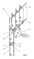
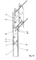
- Figure 1 is an element gate in front view of a window and in Figure 2 the Movement sequence illustrating side view of the same.
- the element gate in Figure 1 in the closed position in the vertical Guide rails 1 located plate elements 3.
- the elevator device 13 In the magazine section 2 is only the elevator device 13 indicated, which with belts on the last one Plate element or a belt strip 3c attacks.
- two upright sliding bulges 12 which have a starting slope 12a at the bottom exhibit. This is the sliding of the plate elements in the Magazine section 2 facilitates and also scratching the plate surfaces avoided.
- Such lubricants can of course also be made on other manufactured Plate elements are glued on.
- rollers 6a, 6b and 6c as guide elements on both sides intended.
- the axes 6 of the same are formed on the plates and can can of course also be designed as slide cams 6 instead of the rollers.
- the axles 6a, 6b and 6c are the axles with one or two grooves for one Provide expansion ring to be attached.
- Figure 2 is also at the transition to Magazine section 2 a the plate elements automatically in the open and in the Locked locking mechanism 11 indicated. For this, e.g. the indicated Maltese cross with switch to forward and reverse suitable by. the belt strip 3c can be actuated and the plate elements also - if such Execution desired - can hold in intermediate positions.
- the bottom right and top rollers 6a and 6b arranged on the left of the plates guide the plate elements into the Rail guides.
- the plate elements are usually conveyed into the magazine by the sliding surfaces 5, but in this embodiment increased by this protruding thrust surfaces 4.
- the respective width and height of this depends according to the plate or push surface material and the weight of the Plate elements; their height is preferably in the micron range.
- the push surfaces 4 can also with a coating or a covering from a lower adhesion and Material with sliding friction coefficient exist or are stored Contain metal powder, sintered materials or coal. They can also be made from thin ones they are anchored to polished steel sheets of low roughness or material combinations consist.
- the magazine guides 2a-2b-1a-1b naturally have one towards the magazine lower height.
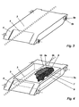
- the Plate element according to Figure 4 is a housing for receiving insulation material educated. At the back there is a cavity 7 receiving this, which is attached to it by an edge 8 or a step seat Cover layer 10 is to be completed.
- the one introduced into the cavity here, for example or glued-in insulating material layer consists of a film 9a under vacuum pressed-in insulation material 9, which is enveloped by a further foam film 9b, which in the exemplary embodiment consists essentially of highly disperse silica consists. You can also insulate in the cavity in the manner of sandwich panels foam, which are glued to the top layer.
- the housing can also be used as a guide that can be inserted laterally at the top and bottom be trained ..
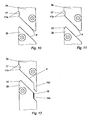
- FIG. 8 shows a particularly simple sealing form in which the step-shaped recess 14c and the strip-shaped lip 15c have a wedge angle corresponding to the sliding surfaces 5 at the top.
- the vertical wall of the recess 14b is here provided with a sealing coating 16 against which the cheek of the sealing strip 15b is pressed in the vertical guide 1 and thus also provides a good sealing closure.
- the same contact seal can also be seen in the reverse arrangement in FIG.
- the sealing means according to the invention can, as usual, be completed by sealing means comprising resilient sealing strips, brushes or ball bearing strips in the vertical guide rails 1-1.
- FIG. 10 shows, according to the invention the partial task of preventing rainwater from penetrating can also be solved in a different way by drip edges 17a, which are provided on an arch 17 at the bottom of the plate elements 3 above the sliding or pushing surfaces 4-5.
- drip edges 17a which are provided on an arch 17 at the bottom of the plate elements 3 above the sliding or pushing surfaces 4-5.
- the drip edges 17a can be assigned a chamfer 18 on the upper sides of the respectively following plate elements, which chamfer has a drainage surface which is directed downwards from the inside to the outside.
- a density — here primarily to avoid an air bridge — can also be applied to the other inward side of the plate elements by means of a projecting sealing strip 15c here each upper plate element can be achieved, which is fitted into a sealing niche 14c provided with a sealing coating 16 on the underside of the respective following plate. All touch seals shown can, of course, be carried out figuratively on the other side of the plate.
Landscapes
- Engineering & Computer Science (AREA)
- Structural Engineering (AREA)
- Architecture (AREA)
- Civil Engineering (AREA)
- Specific Sealing Or Ventilating Devices For Doors And Windows (AREA)
- Moulds For Moulding Plastics Or The Like (AREA)
Abstract
Description
Die Erfindung betrifft ein Elementtor mit vorzugsweise rechteckförmigen Plattenelementen, die mit ihren Langseiten horizontal ausgerichtet und mit ihren Schmalseiten in seitlichen Führungsschienen geführt sind
- und im geschlossenen Zustand des Elementtores senkrecht aufeinander stehen
- und im offenen Zustand in einem Magazin parallel zueinander gestapelt sind,
- wobei vorzugsweise ein Zuggurt das unterste Plattenelement und dgl. beim Schließen des Elementtores zusammen mit den darüber befindlichen Plattenelementen anhebt
- und wobei die Plattenelemente der Reihe nach entlang abgewinkelter Führungsschienen mit Leitelementen geführt und vermittels von an ihren Ober- und Unterseiten ausgebildeten in Magazinrichtung abfallenden Gleitflächen in das Magazin überführt werden.
- and stand perpendicular to each other when the element gate is closed
- and are stacked in a magazine parallel to each other when open,
- preferably a tension belt lifts the lowermost plate element and the like when the element gate is closed together with the plate elements located above it
- and wherein the plate elements are guided in series along angled guide rails with guide elements and are transferred into the magazine by means of sliding surfaces formed on their top and bottom sides in the magazine direction.
Ein derartiges Elementtor ist aus der JP 07 310 483 A bekannt. Die einzelnen Plattenelemente sind durch oben und unten an ihren Schmalseiten angeordnete Rollen in einem senkrechten Schienenabschnitt geführt und mit den oberen Rollen in einem horizontal abgewinkelten das Magazin darstellenden Schienenabschnitt gespeichert. Die Überführung in das Magazin wird durch zu dem Magazin hin abfallende Gleitflächen an den Unter- und Oberseiten der Plattenelemente bewirkt, durch welche das jeweils am Magazin ankommende Plattenelement sich durch die Keilschubwirkung der Gleitflächen neben das dort befindliche schiebt und dieses dabei in das Magazin befördert. Die beim Überschieben in das Magazin zu überwindende Haft- und Gleitreibung hängen neben dem Werkstoff und der Flächenpressung stark von dem jeweils durch äußere Einflüsse wie Temperatur, Staub- und Feuchtigkeitseinwirkung verursachten Verschleiß bzw. Abrieb verursachten Zustand der Gleitflächen ab. Bei der in der angezogenen Druckschrift ersichtlichen Einbauweise des Elementors, bei welcher die Gleitflächen von der Gebäudeaußenseite her gesehen von oben links nach unten rechts abfallen, können alle genannten Verschleißmechanismen auftreten und hierbei kann vor allem auch bei Regenbefall das außen an den Plattenelementen ablaufende Wasser in die Spalte zwischen den Gleitflächen eindringen und in der kalten Jahreszeit gefrieren. Der nicht vermeidbare Verschleiß kann hierbei leicht zum Totalausfall führen. Sieht man dem abzuhelfen eine Einbauweise mit einem vor den Fenstern liegenden Magazin vor bei welcher zwar die Gleitflächen von außen gesehen von unten nach oben verlaufen und so das ablaufende Regenwasser nicht eindringt, kann dennoch Staub und Luftfeuchttigkeit die Gleitflächen in einer Korrosion und Abrieb verursachenden Weise verschmutzen. Auch muß man hierbei eine Verkleinerung der Fensterfläche in Kauf nehmen und die Montage und auch die Wartung oder eine Reparatur ist bei dieser Einbauweise äußerst schwierig zu bewerkstelligen, da man diese nur an der Gebäudeaußenseite vornehmen kann. Bei beiden Einbauversionen kommen bei mit Dämmmaterial oder Dämmstoffplatten kombinierten Plattenelementen, wie sie besonders für Niedrigenergie- bzw. Passivhäuser verwendet werden, bei den hier gewöhnlich recht großen Temperaturunterschieden zwischen der Außen- und der Innentemperatur weitere durch das Verbiegen der Plattenelemente bedingte Schäden. Die Biegemomente führen in der Regel zur Zerstörung des Dämmstoffgefüges und können sich auch auf die Funktionsweise der Gleitflächen störend auswirken.Such an element gate is known from JP 07 310 483 A. The single ones Plate elements are by rollers arranged at the top and bottom of their narrow sides guided in a vertical rail section and with the upper rollers in one stored horizontally angled rail section representing the magazine. The transfer into the magazine is made by falling towards the magazine Sliding surfaces on the undersides and tops of the plate elements caused by which the plate element arriving at the magazine is characterized by the Wedge pushing effect of the sliding surfaces next to the one located there and pushing it along transported to the magazine. The one to be overcome when pushed into the magazine Static and sliding friction depend strongly on the material and the surface pressure of which by external influences such as temperature, dust and Moisture caused wear or abrasion caused condition of the sliding surfaces. The one shown in the cited publication Installation of the element, in which the sliding surfaces from the outside of the building seen from top left to bottom right, all of the above Wear mechanisms occur and this can occur especially when it is raining the water running outside on the plate elements into the gap between the Penetrate sliding surfaces and freeze in the cold season. The unavoidable Wear can easily lead to total failure. Can you see the remedy a way of installation with a magazine in front of the windows in which seen from the outside, the sliding surfaces run from bottom to top and so that running rainwater does not penetrate, dust and humidity can still Contaminate sliding surfaces in a manner that causes corrosion and abrasion. You also have to accept a reduction in the window area and the Assembly and maintenance or repairs are extreme with this type of installation difficult to do because you can only do this on the outside of the building can. Both installation versions come with insulation material or Insulation boards combined board elements, as they are especially for Low-energy or passive houses are used, which are usually right here large temperature differences between the outside and inside temperature further damage caused by the bending of the plate elements. The Bending moments usually lead to the destruction of the insulation structure and can also interfere with the functioning of the sliding surfaces.
Ausgehend hiervon liegt der Erfindung die Aufgabe zugrunde ein Elementtor der eingangs beschriebenen Art zu schaffen, bei welchem die Gleitflächen der Plattenelemente gegenüber den oben beschriebenen Umwelteinflüssen in beiden möglichen Einbauversionen geschützt sind und auch eine größere Biegefestigkeit der Plattenelemente erreicht wird, durch welche auch eine schadlose Anwendung von mit Dämmschichten oder Dämmplatten versehenen Plattenelementen ermöglicht wird.Proceeding from this, the object of the invention is an element gate to create the type described above, in which the sliding surfaces of the Plate elements compared to the environmental influences described above in both possible installation versions are protected and also a greater bending strength of the Plate elements is achieved, through which a harmless application of with Insulation layers or insulation panels provided with panel elements is made possible.
Diese Aufgabe wird erfindungsgemäß durch mehrere in den Ansprüchen angeführte sonst an sich eigenständigen und neuen Ausbildungen der Elementtore gelöst.This object is achieved according to the invention by several claims otherwise resolved in an independent and new form of the element gates.
Durch die erfindungsgemäßen an je einer oder beiden Seiten der Gleitflächen der Plattenelemente sich anschließenden unterschiedliche Arten von Berührungsdichtungen wird eine verschleißarme Funktion mit längerer Standzeit der Elementtore gewährleistet. Weiterhin können nunmehr die erfindunsgemäßen Plattenelemente in beiden möglichen Einbauversionen verwendet werden, sodass diese nunmehr auch in größerer Stückzahl kostensparender herzustellen sind und damit ein besonders günstiges bisher nicht erreichtes Kosten-Nutzenverhältnis der erfindungsgemäßen Elementtore bei längstmöglicher Standzeit zu verzeichnen ist. Durch die Profilformen der erfindungsgemäßen Berührungsdichtungen wird auch die dynamische Steifigkeit der Plattenelemente an sich und gegenüber den durch die temperaturbedingten Dehn- und Schrumpfbewegungen verursachten Beanspruchungen wesentlich erhöht. Sie können daher unbeschadet als Sandwichplatten oder erfmdungsgemäß mit in einer Gehäusehöhlung vorgesehenen leicht bröselnden hochaktiven porösen Dämmstoffen ausgeführt oder sonstwie mit Dämmplatten kombiniert werden. Die Stabilität der so ausgebildeten Plattenelemente wird weiterhin durch den Erfindungsgedanken erhöht, die Plattenelemente mit den Berührungsdichtungsformen und seitlichen Leitelementen und sonstigen Funktionsteilen ggf. mit an der Rückseite Dämmstoffe oder Dämmplatten aufnehmenden Gehäuse- oder Halteformen sozusagen in einem Guß im Wege von Urform- und ggf. auch Umformtechniken herzustellen. Hierbei lassen sich z.B. Plattenelemente aus Leichtmetallgußstoffen, leichte Plattenelemente im Kunststoffpreß- oder -spritzverfahren und Lichtleitplatten in der Glasschmelze fertigen, welche durch ihre die einzelnen Zwecklösungen in überraschender Weise vereinigenden und eine größere Formsteifheit gewährleistende Bauweise den Dauerbeanspruchungen bestens gewachsen sind. Hierbei kann man die Plattenelemente mit allen beschriebenen Funktionsteilen und weiterhin z.B. mit wenigstens zwei streifenförmigen die Haft- und Gleitreibungsbeanspruchung zum und im Magazin vermindernden und auch ein Verkratzen der Plattenoberflächen verhindernden Gleitwölbungen versehen. In vorteilhafter Weise kann man sie aus kleine Haft- und Gleitreibungszahlen aufweisenden Werkstoffen herstellen oder die aus beliebigen Werkstoffen bestehenden Plattenelemente an wenigstens einer der Gleitflächen mit solchen Werkstoffen beschichten oder belegen. Nach einem weiteren Gedanken der Erfindung können auch wenigstens an den Gleitflächen vorstehende und diese entlastende streifenförmige Gleitflächen z.B. aus solchen Werkstoffen vorgesehen werden. Eine weitere wirtschaftliche Lösung besteht z.B in einer Beschichtung bzw. Belegung der Gleit- oder Schubflächen der sonst aus einem beliebigen Material bestehenden Plattenelemente mit einem Überzug aus dem eine außerordentlich kleine Gleitreibungszahl µ aufweisenden sonst sehr teuren Polytetrafluoräthylen (PTFE) oder die so beschichteten Plattenelemente mit Plattenelementen paaren welche mit polierten rostfreien Stahlbelägen versehenen sind. Mit einer solchen Paarung wird eine Gleitreibungszahl von µ 0,04...0,022 erreicht. Die Erfindung eröffnet auch hiermit bisher unerreichte Möglichkeiten.By the invention on one or both sides of the sliding surfaces of the Panel elements adjoining different types of Touch seals become a low-wear function with a longer service life Element gates guaranteed. Furthermore, the inventive Plate elements can be used in both possible built-in versions, so this are now more cost-effective to produce in larger numbers and thus a Particularly favorable cost-benefit ratio of the Element gates according to the invention can be recorded with the longest possible service life. Due to the profile shapes of the contact seals according to the invention, the dynamic rigidity of the plate elements per se and compared to that by the stresses caused by temperature-related expansion and shrinking movements significantly increased. They can therefore be used undamaged as sandwich panels or According to the invention with slightly crumbling provided in a housing cavity highly active porous insulation materials or otherwise with insulation boards be combined. The stability of the plate elements thus formed continues increased by the inventive concept, the plate elements with the Touch seal shapes and side guide elements and others Functional parts, if necessary, with insulation materials or insulation panels on the back receiving housing or holding forms, so to speak, in one pour by way of To produce master forms and, if necessary, also forming techniques. Here, e.g. Plate elements made of light metal castings, light plate elements in Plastic pressing or injection molding process and light guide plates in the glass melt manufacture, which by their individual purpose solutions in a surprising way unifying and ensuring greater stiffness the construction Permanent stresses have grown well. Here you can Panel elements with all the functional parts described and further e.g. With at least two strip-like the static and sliding friction to and reducing and scratching the plate surfaces in the magazine prevent sliding camber. You can advantageously take them out produce small materials with static and sliding friction or the plate elements made of any materials on at least one of the Coat or cover sliding surfaces with such materials. After another Thoughts of the invention can also protrude at least on the sliding surfaces this relieving strip-shaped sliding surfaces e.g. from such materials be provided. Another economical solution is one Coating or covering of the sliding or shear surfaces which otherwise from one any material existing panel elements with a coating of one extremely small sliding friction coefficient µ, otherwise very expensive Polytetrafluoroethylene (PTFE) or the plate elements coated with it Plate elements pair which are provided with polished stainless steel coverings are. With such a pairing, a sliding friction coefficient of µ 0.04 ... 0.022 reached. The invention hereby also opens up unprecedented possibilities.
Nachfolgend wird die Erfindung anhand bevorzugter Ausführungsbeispiele in der
Zeichnung näher erläutert. Es zeigen:
Die in der Zeichnung dargestellten Plattenelemente sind z.B. in der oben erwähnten
Weise im Wege einer Urformtechnik aus einem Plastwerkstoff hergestellt. In Figur 1
ist ein Elementtor in Vorderansicht an einem Fenster und in Figur 2 eine den
Bewegungsablauf veranschaulichende Seitenansicht desselben dargestellt. Zu sehen
ist das Elementtor in Figur 1 in der Verschlußstellung der in den senkrechten
Führungsschienen 1 befindlichen Plattenelemente 3. In dem Magazinabschnitt 2 ist
lediglich die Aufzugsvorrichtung 13 angedeutet, welche mit Gurten an dem letzten
Plattenelement oder einer Gurtleiste 3c angreift. An den Plattenelementen 3 sieht man
ferner zwei aufrechte Gleitwölbungen 12, welche unten eine Anlaufsteigung 12a
aufweisen. Hiermit wird das Aneinandergleiten der Plattenelemente im
Magazinabschnitt 2 erleichtert und auch eine Verkratzen der Plattenoberflächen
vermieden. Derartige Gleitmittel können natürlich auch an anders hergestellten
Plattenelementen aufgeklebt werden. An den einzelnen Plattenelementen sind ferner,
wie in Figur 2, 3 und 4 zu sehen, beiderseits Rollen 6a,6b und 6c als Leitelemente
vorgesehen. Die Achsen 6 derselben sind an den Platten angeformt und können
natürlich auch an Stelle der Rollen als Gleitnocken 6 ausgebildet sein. Zur Halterung
der Rollen 6a,6b und 6c sind die Achsen mit einer oder zwei Rillen für einen
aufzusetzenden Spreizring versehen. In Figur 2 ist ferner am Übergang in den
Magazinabschnitt 2 ein die Plattenelemente automatisch in der Offen- und in der
Verschlußstellung arretierendes Gesperre 11 angedeutet. Hierfür ist z.B. das
angedeutete Malteserkreuz mit Umschaltung auf Vor- und Rücklauf geeignet, welches
durch. die Gurtleiste 3c betätigbar ist und die Plattenelemente auch -wenn eine solche
Ausführung erwünscht- in Zwischenstellungen halten kann. Die unten rechts und oben
links an den Platten angeordneten Rollen 6a und 6b führen die Plattenelemente in den
Schienenführungen. In das Magazin befördert werden die Plattenelemente in der Regel
durch die Gleitflächen 5, bei dieser Ausführung jedoch durch an diesen erhöht
vorstehenden Schubflächen 4. Die jeweilige Breite und die Höhe dieser richtet sich
nach dem Platten- bzw. Schubflächenwerkstoff und dem Gewicht der
Plattenelemente; ihre Höhe liegt vorzugsweise im Mikronbereich. Die Schubflächen 4
können auch mit einer Beschichtung oder einem Belag aus einem eine geringere Haftund
Gleitreibungszahl aufweisenden Werkstoff bestehen oder eingelagertes
Metallpulver, Sinterwerkstoffe oder Kohle enthalten. Auch können sie aus dünnen an
ihnen verankerten polierten Stahlblechen geringer Rauhigkeit oder Materialpaarungen
bestehen. Zum Magazin hin haben die Magazinführungen 2a-2b-1a-1b natürlich eine
geringere Höhe. Durch die zusätzlichen Rollen 6c sind die Platten in Verbindung mit
den übrigen Rollen (6a,6b) in den senkrechten Führungen 1a-1b so gehalten dass sie
beim Bewegen in dem aufrechten Abschnitt nicht seitlich ausbrechen können. Das
Plattenelement gemäß Figur 4 ist als Gehäuse zur Aufnahme von Dämmmaterial
ausgebildet. An seiner Rückseite ist eine dieses aufnehmende Höhlung 7 ausgespart,
welche durch eine an ihrem Rand 8 oder einem Stufensitz daran befestigte
Deckschicht 10 abzuschließen ist. Die hier beispielsweise in die Höhlung eingebrachte
bzw. eingeklebte Isolierstoffschicht besteht aus einem in eine Folie 9a unter Vacuum
eingepreßten und von einer weiteren Schaumstofffolie 9b umhüllten Dämmmaterial 9,
welches beim Ausführungsbeispiel im wesentlichen aus hochdisperser Kieselsäure
besteht. In die Höhlung kann man auch Dämmmassen nach Art von Sandwichplatten
einschäumen, welche mit der Deckschicht verklebtsind. Das Gehäuse kann auch als
eine oben und unten seitlich einschiebbare Dämmplatten umfassende Führung
ausgebildet sein..The plate elements shown in the drawing are e.g. in the above
Made from a plastic material using a master molding technique. In Figure 1
is an element gate in front view of a window and in Figure 2 the
Movement sequence illustrating side view of the same. To see
is the element gate in Figure 1 in the closed position in the
In der hinter dem Fenster gelegenen dargestellten Einbauversion des Magazins könnte,
wie eingangs ausgeführt, bei Regenbefall das Wasser an den Plattenelementen durch
die von oben nach unten verlaufenden Schub- und Gleitflächen (4-5) bzw. den
Gleitflächen 5 eindringen und im Winter gefrieren. Auch besteht, wie auch bei der
anderen Einbauweise mit vor dem Fenster gelegenen Magazin, eine Feuchtigkeit und
Staub einführende Luftbrücke. Um diese Einwirkungen auszuschalten sind
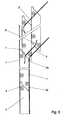
erfindungsgemäß, wie in Figur 5 im Bewegungsablaufbild und den folgenden Figuren
6 - 8 im Einzelnen zu sehen, vorne an den Gleitflächen 5 der Plattenelemente 3
angrenzende Berührungsdichtungen 14-15 angeordnet. Diese bestehen aus an den
Unterseiten 3a der Plattenelemente angordneten Nischen 14 und an deren Oberseiten
3b angeordneten in diese formschlüssig eingepassten Dichtlippen 15. Bei der in Figur
6 ersichtlichen Ausführungsform besteht die Dichtlippe aus einer Kuppe 15a welche
in eine Einwölbung 14a an der Dichtnische 14 eingreift. Da in dieser der
Dichtungsspalt von außen zunächst etwas ansteigt, wird das Eindringen von außen an
den Plattenelementen ablaufendem Regenwasser verhindert. und auch eine
Abdichtung gegen weitere Umwelteinflüsse erzielt. Gemäß Figur 8 ist die aus
Einwölbungen 14a und Kuppen 15a bestehende Anordnung verdoppelt, wobei sich
eine überaus wirksame Labyrinthdichtung ergibt. Wölbung und Kuppel sind auch
hierbei so angeordnet, daß die Verschiebebewegung nicht behindert wird. Mit dem in
den Figuren ersichtlichen Dichtungsbelag 16 wird eine gegen alle weiteren äußeren
Einflüsse wirksame Abdichtung erzielt. In Figur 9 schließlich ist eine besonders
einfache Abdichtform zu sehen, bei welcher die stufenförmige Nische 14c und die
leistenförmige Lippe 15c oben eine den Gleitflächen 5 entsprechenden Keilwinkel
aufweisen. Die senkrechte Wand der Nische 14b ist hier mit einem Dichtungsbelag 16
versehen, gegen welche die Wange der Dichtleiste 15b in der senkrechten Führung 1
angepreßt ist und auch so einen guten dichtenden Abschluß bewirkt. Eine gleiche
Berührungsdichtung ist auch in Figur 12 in umgekehrter Anordnung zu sehen. Die
erfindungsgemäßen Dichtungsmittel können wie üblich durch in den senkrechten
Führungsschienen 1-1 die seitlichen Plattenenden mit federnden Dichtungs-, Bürstenoder
Kugellagerstreifen umfassenden Dichtungsmitteln vervollständigt sein.
Wie Figur 10 zeigt, kann erfindungsgemäß die Teilaufgabe der Vermeidung eines
Eindringens von Regenwasser auch in anderer Weise durch Abtropfkanten 17a gelöst
werden, welche an einer Einwölbung 17 unten an den Plattenlementen 3 oberhalb der
Gleit- bzw. Schubflächen 4-5 vorgesehen sind. In einer weiteren Ausgestaltung
derselben gemäß Figur 11 und 12 kann den Abtropfkanten 17a an den Oberseiten der
jeweils folgenden Plattenelemente eine Fase 18 zugeordnet sein, welche eine von
innen nach außen abwärts gerichteten Ablauffläche aufweist. Hierbei, wie natürlich
auch zusätzlich bei den in den Figuren 6-9 beschriebenen Ausführungen, kann gemäß
Figur 12 eine Dichte -hier vor allem zur Vermeidung einer Luftbrücke- auch an der
andern nach innen gelegenen Seite der Plattenelemente durch eine vorspringende
Dichtleiste 15c hier an dem jeweils oberen Plattenelement erzielt werden, welche in
eine mit einem Dichtungsbelag 16 versehene Dichtnische 14c an der Unterseite der
jeweils folgenden Platte eingepaßt ist. Alle dargestellten Berührungsdichtungen
können natürlich im übertragenen Sinn an der jeweils anderen Plattenseite ausgeführt
werden. In the built-in version of the magazine located behind the window, as stated at the beginning, the water on the plate elements could penetrate through the pushing and sliding surfaces (4-5) or the sliding
As FIG. 10 shows, according to the invention the partial task of preventing rainwater from penetrating can also be solved in a different way by
- 11
- Führungsschienen, senkrechte; 1a und 1b Hilfsführungen MagazinGuide rails, vertical; 1a and 1b auxiliary guides magazine
- 22
-
Magazin Führungsschienen 2a-2b
Magazine guide rails 2a-2b - 33
- Plattenelemente, 3a Plattenunterseite, 3b Plattenoberseite, 3c GurtleisterPlate elements, 3a plate underside, 3b plate underside, 3c belt insert
- 44
- Schubflächepushing surface
- 55
- Gleitflächesliding surface
- 66
- Gleitnocke, 6a Achsen 6b Rollen (Funktionselemente)Slide cam, 6a axes 6b rollers (functional elements)
- 77
- Plattenaussparung, Höhlung, 7a HöhlungbodenPanel recess, cavity, 7a cavity floor
- 88th
- HöhlungsrandHöhlungsrand
- 99
- Dämmmaterial, 9a Folie, 9b SchaumstoffumhüllungInsulation material, 9a film, 9b foam covering
- 1010
- Deckschichttopcoat
- 1111
- Gesperre, MalteserkreuzLock, Maltese Cross
- 1212
- Gleitwölbung, 12a AnlaufflächeSliding curvature, 12a contact surface
- 1313
- Aufzugsvorrichtungwinder
- 1414
- Berührungsdichtung - Dichtnische, 14a Einwölbung, 14b and 14c DichtsitzTouch seal - sealing niche, 14a concavity, 14b and 14c sealing seat
- 1515
-
Berührungsdichtung - Dichtlippen, 15a Kuppel 15b und 15c DichtleisteContact seal - sealing lips,
15a dome - 1616
- Dichtungsbelagseal coating
- 1717
- Einwölbung, 17a AbtropfkanteArching, 17a drip edge
- 1818
- Fasechamfer
Claims (10)
Applications Claiming Priority (11)
| Application Number | Priority Date | Filing Date | Title |
|---|---|---|---|
| DE2001108702 DE10108702A1 (en) | 2001-06-12 | 2001-02-23 | Sliding door, composed of separate horizontal boards in a vertical array, has guide rails to shift the boards into a parallel stack at a magazine when the door is moved upwards for opening |
| DE10108702 | 2001-02-23 | ||
| DE10118928 | 2001-04-18 | ||
| DE2001118928 DE10118928A1 (en) | 2001-04-18 | 2001-04-18 | Sliding door, composed of separate horizontal boards in a vertical array, has guide rails to shift the boards into a parallel stack at a magazine when the door is moved upwards for opening |
| DE10121094 | 2001-04-23 | ||
| DE10121094 | 2001-04-23 | ||
| DE10121084 | 2001-04-28 | ||
| DE10122819 | 2001-05-11 | ||
| DE10122819 | 2001-05-11 | ||
| DE10127603 | 2001-05-17 | ||
| DE2001127603 DE10127603A1 (en) | 2001-02-23 | 2001-06-12 | Sliding door, composed of separate horizontal boards in a vertical array, has guide rails to shift the boards into a parallel stack at a magazine when the door is moved upwards for opening |
Publications (2)
| Publication Number | Publication Date |
|---|---|
| EP1234946A2 true EP1234946A2 (en) | 2002-08-28 |
| EP1234946A3 EP1234946A3 (en) | 2003-08-20 |
Family
ID=27512406
Family Applications (1)
| Application Number | Title | Priority Date | Filing Date |
|---|---|---|---|
| EP01119612A Withdrawn EP1234946A3 (en) | 2001-02-23 | 2001-08-20 | Sectional door |
Country Status (1)
| Country | Link |
|---|---|
| EP (1) | EP1234946A3 (en) |
Cited By (5)
| Publication number | Priority date | Publication date | Assignee | Title |
|---|---|---|---|---|
| DE10329798A1 (en) * | 2003-07-01 | 2005-02-24 | Guido Langenbach | sectional |
| US10125540B2 (en) | 2014-01-29 | 2018-11-13 | Gmp Nv | Sectional door with lifting mechanism |
| US20220074262A1 (en) * | 2018-12-28 | 2022-03-10 | Simon-Andreas MAURER | Retractable Partition Wall |
| WO2022072395A1 (en) | 2020-09-30 | 2022-04-07 | Cornellcookson, Llc | Vertically stacking panel door with cam levers |
| US11927055B2 (en) | 2020-10-05 | 2024-03-12 | Cornellcookson, Llc | Vertically stacking panel door with a lifting cam |
Citations (1)
| Publication number | Priority date | Publication date | Assignee | Title |
|---|---|---|---|---|
| JPH07310483A (en) | 1994-04-15 | 1995-11-28 | Shinko Ind:Kk | Shutter |
Family Cites Families (3)
| Publication number | Priority date | Publication date | Assignee | Title |
|---|---|---|---|---|
| NL8502956A (en) * | 1985-10-30 | 1987-05-18 | Carmen Francisca Maria Van Vil | Guard for building opening - has one panel moved in and out of housing and others guided on wheels |
| DE19519529C1 (en) * | 1995-05-27 | 1996-06-05 | Top Form Gmbh Fenster Tueren U | Staggered lifting door for garage or hangar, etc. |
| AU3577397A (en) * | 1997-06-25 | 1999-01-04 | Charles E. Cook | Improved closure system |
-
2001
- 2001-08-20 EP EP01119612A patent/EP1234946A3/en not_active Withdrawn
Patent Citations (1)
| Publication number | Priority date | Publication date | Assignee | Title |
|---|---|---|---|---|
| JPH07310483A (en) | 1994-04-15 | 1995-11-28 | Shinko Ind:Kk | Shutter |
Cited By (8)
| Publication number | Priority date | Publication date | Assignee | Title |
|---|---|---|---|---|
| DE10329798A1 (en) * | 2003-07-01 | 2005-02-24 | Guido Langenbach | sectional |
| DE10329798B4 (en) * | 2003-07-01 | 2009-04-09 | Guido Langenbach | sectional |
| US10125540B2 (en) | 2014-01-29 | 2018-11-13 | Gmp Nv | Sectional door with lifting mechanism |
| US20220074262A1 (en) * | 2018-12-28 | 2022-03-10 | Simon-Andreas MAURER | Retractable Partition Wall |
| US12398592B2 (en) * | 2018-12-28 | 2025-08-26 | Simon-Andreas MAURER | Retractable partition wall |
| WO2022072395A1 (en) | 2020-09-30 | 2022-04-07 | Cornellcookson, Llc | Vertically stacking panel door with cam levers |
| EP4222333A4 (en) * | 2020-09-30 | 2024-10-30 | Cornellcookson, Llc | VERTICAL STACKING PANEL DOOR WITH CAM LEVERS |
| US11927055B2 (en) | 2020-10-05 | 2024-03-12 | Cornellcookson, Llc | Vertically stacking panel door with a lifting cam |
Also Published As
| Publication number | Publication date |
|---|---|
| EP1234946A3 (en) | 2003-08-20 |
Similar Documents
| Publication | Publication Date | Title |
|---|---|---|
| DE202008013043U1 (en) | Lift-slide window or door and sealing element | |
| EP1554455A1 (en) | Spacer for panes of multilayer insulation glazings | |
| EP1431501B1 (en) | Sliding door assembly | |
| EP2317054B1 (en) | Sliding door | |
| DE2933836A1 (en) | DOOR HEAD GASKET FOR SHUTTER DOORS OR THE LIKE | |
| DE60306623T2 (en) | COMBINATION OF SEALING FRAME, LIGHT LOCK AND WEAR INSERT FOR KIPPLOR | |
| DE29808292U1 (en) | End profile for a door leaf | |
| EP2546448B1 (en) | Device for pushing a slide element | |
| AT392327B (en) | STRING-SHAPED SLEEVE GASKET FOR WINDOWS, DOORS OR THE LIKE ROOM LOCKING BODIES | |
| EP1354545B1 (en) | Sealing for a shower partition | |
| EP0370324A2 (en) | Door leaf | |
| EP1234946A2 (en) | Sectional door | |
| DE8632855U1 (en) | Elastic sealing profile as a stop profile for doors or similar. | |
| DE19829783A1 (en) | Sliding door or dividing wall installation | |
| EP0730068A1 (en) | Skylight | |
| DE3310230A1 (en) | Window | |
| EP2487313A1 (en) | Frame construction for a window or door | |
| DE102016125334A1 (en) | Window or door with a seal assembly and rebate seal | |
| DE19911022A1 (en) | Vehicle window with a fixed and a sliding pane has a tapering wedge shape at one side with additional guides for the second window at the frame and a wedge to compensate for lack of parallelism between the guides | |
| DE202019102768U1 (en) | Skylight design system | |
| DE10250284A1 (en) | Sectional shutter has a number of parallel slats each formed by two interlocking shells fitted with end caps and filled with a setting foam insulation | |
| DE69415002T2 (en) | DEVICE FOR AN OPENING ROOF | |
| DE102005009265B4 (en) | Sectional | |
| WO2002008558A1 (en) | Closing element, in particular a door | |
| DE202011050625U1 (en) | chain drive |
Legal Events
| Date | Code | Title | Description |
|---|---|---|---|
| PUAI | Public reference made under article 153(3) epc to a published international application that has entered the european phase |
Free format text: ORIGINAL CODE: 0009012 |
|
| AK | Designated contracting states |
Kind code of ref document: A2 Designated state(s): AT BE CH CY DE DK ES FI FR GB GR IE IT LI LU MC NL PT SE TR |
|
| AX | Request for extension of the european patent |
Free format text: AL;LT;LV;MK;RO;SI |
|
| PUAL | Search report despatched |
Free format text: ORIGINAL CODE: 0009013 |
|
| AK | Designated contracting states |
Designated state(s): AT BE CH CY DE DK ES FI FR GB GR IE IT LI LU MC NL PT SE TR |
|
| AX | Request for extension of the european patent |
Extension state: AL LT LV MK RO SI |
|
| 17P | Request for examination filed |
Effective date: 20040115 |
|
| AKX | Designation fees paid |
Designated state(s): DE |
|
| STAA | Information on the status of an ep patent application or granted ep patent |
Free format text: STATUS: THE APPLICATION IS DEEMED TO BE WITHDRAWN |
|
| 18D | Application deemed to be withdrawn |
Effective date: 20040302 |