EP1234941A2 - Support device for mounting a hinge to a door or window leaf or to a door frame - Google Patents
Support device for mounting a hinge to a door or window leaf or to a door frame Download PDFInfo
- Publication number
- EP1234941A2 EP1234941A2 EP02000320A EP02000320A EP1234941A2 EP 1234941 A2 EP1234941 A2 EP 1234941A2 EP 02000320 A EP02000320 A EP 02000320A EP 02000320 A EP02000320 A EP 02000320A EP 1234941 A2 EP1234941 A2 EP 1234941A2
- Authority
- EP
- European Patent Office
- Prior art keywords
- eccentric
- door
- frame
- window sash
- section
- Prior art date
- Legal status (The legal status is an assumption and is not a legal conclusion. Google has not performed a legal analysis and makes no representation as to the accuracy of the status listed.)
- Granted
Links
Images

Classifications
-
- E—FIXED CONSTRUCTIONS
- E05—LOCKS; KEYS; WINDOW OR DOOR FITTINGS; SAFES
- E05D—HINGES OR SUSPENSION DEVICES FOR DOORS, WINDOWS OR WINGS
- E05D7/00—Hinges or pivots of special construction
- E05D7/04—Hinges adjustable relative to the wing or the frame
- E05D7/0415—Hinges adjustable relative to the wing or the frame with adjusting drive means
-
- E—FIXED CONSTRUCTIONS
- E05—LOCKS; KEYS; WINDOW OR DOOR FITTINGS; SAFES
- E05Y—INDEXING SCHEME ASSOCIATED WITH SUBCLASSES E05D AND E05F, RELATING TO CONSTRUCTION ELEMENTS, ELECTRIC CONTROL, POWER SUPPLY, POWER SIGNAL OR TRANSMISSION, USER INTERFACES, MOUNTING OR COUPLING, DETAILS, ACCESSORIES, AUXILIARY OPERATIONS NOT OTHERWISE PROVIDED FOR, APPLICATION THEREOF
- E05Y2900/00—Application of doors, windows, wings or fittings thereof
- E05Y2900/10—Application of doors, windows, wings or fittings thereof for buildings or parts thereof
- E05Y2900/13—Type of wing
- E05Y2900/132—Doors
-
- E—FIXED CONSTRUCTIONS
- E05—LOCKS; KEYS; WINDOW OR DOOR FITTINGS; SAFES
- E05Y—INDEXING SCHEME ASSOCIATED WITH SUBCLASSES E05D AND E05F, RELATING TO CONSTRUCTION ELEMENTS, ELECTRIC CONTROL, POWER SUPPLY, POWER SIGNAL OR TRANSMISSION, USER INTERFACES, MOUNTING OR COUPLING, DETAILS, ACCESSORIES, AUXILIARY OPERATIONS NOT OTHERWISE PROVIDED FOR, APPLICATION THEREOF
- E05Y2900/00—Application of doors, windows, wings or fittings thereof
- E05Y2900/10—Application of doors, windows, wings or fittings thereof for buildings or parts thereof
- E05Y2900/13—Type of wing
- E05Y2900/148—Windows
Definitions
- the invention relates to a tape take-up device for mounting on a door or window sash or on a Frame, with one on the door or window sash or on the frame attachable receptacle in which threaded holes are formed are, a fastening part in which elongated holes are formed through which bolts with the receptacle-side Threaded holes can be brought into thread engagement are, and an adjustment eccentric with a circular or cylindrical section without play the receiving piece and with an eccentric section, an eccentric bore of the fastening part be upheld.
- the adjusting eccentrics of the type described above Belt take-up devices are used for vertical adjustment, a horizontal adjustment or depending on the installation situation also a depth adjustment of the fastener with respect to reach the receiving piece to the door or window sash in the height, width or depth direction of the through the Position the door or window opening formed correctly. Because partially when actuating the adjusting eccentric considerable forces have to be applied and derived, is the adjustment eccentric of known tape take-up devices on its the frame or the door or window sash facing end section in on the frame or on the door or Window sash provided bearing elements rotatably supported. This results in a comparative one large dimension of the tape take-up device in its thickness direction, taking additional storage measures on the frame or on the door or window sash need to have an abutment for the corresponding end section of the adjustment eccentric.
- the largest diameter of the eccentric section is the smallest Diameter of the eccentric hole on the fastening part side corresponds to a considerable space saving.
- the result is an exact and with little effort Realizable adjustment of the door or window sash in the height direction the door or window opening formed by the frame, when the longitudinal direction of the fastener side Slots is oriented in the vertical direction and the the eccentric bore on the fastening part side has its largest diameter has in the horizontal direction.
- the receiving piece can be used for its spatial positioning of the contact surface have holes through which Screws in the door or window sash or frame side Contact surface in the door or window sash or in the frame are screwed in.
- the adjustment eccentric is one with respect to its circular or cylindrical section arranged in the middle Has polygonal recess, in the one of the receiving piece facing away from the front of the fastener Actuating polygon is insertable.
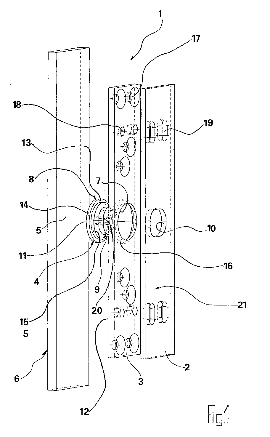
- Figures 1 to 5 is the tape take-up device according to the invention 1 shown in one embodiment, by means of which is an adjustment of the door leaf in the vertical height direction same with respect to the frame is possible.
- the door surface or frame-side contact surface 5 can for example be formed by a hollow profile 6.
- FIG. 1 in conjunction with FIGS. 4 and 5, is the receiving piece 3 between the fastening part 2 and the door surface or frame-side contact surface 5 arranged, in a roughly centered in the receptacle 3 provided holding recess 7 a circular or cylindrical Section 8 of the adjusting eccentric 4 is held.
- the adjusting eccentric 4 projects into an eccentric bore formed approximately centrally in the fastening part 2 10, the smallest diameter the largest diameter corresponds to the eccentric section 9 of the adjusting eccentric 4.
- the free end face 11 facing away from the eccentric section 9 of the adjustment eccentric 4 is aligned with that of the frame or Door surface-side contact surface 5 facing rear surface 12 of the receptacle 3.
- the circular or cylindrical section 8 of the adjusting eccentric 4 has a radial step 13 which is circular or cylindrical section 8 of the adjusting eccentric 4 in a rear section 14 on the door leaf or frame side with a comparatively large diameter and one to it coaxial fastening part-side front section 15 with divided into a comparatively small diameter.
- the adjustment eccentric is 4 through its radial stage 13 in cooperation with the radial recess 16 and the system contact between its free end face 11 and the frame or Door wing-side contact surface 5 spatially fixed, however rotatable between the receptacle 3 and the frame or Door wing-side contact surface 5 mounted or held.
- this storage or bracket are none at all the frame-side or door wing-side contact surface 5 to be made Measures required.
- the tape take-up device 1 thus results in a small overall size constructive design of the same, being above in addition, no measures on the hollow profile 6 of the door leaf or the frame must be made to the adjustment eccentric 4 spatially fixed and rotatable to store or hold.
- the receiving piece 3 is in the illustrated embodiment designed with a total of eight holes 17, which are preferably are designed as tapered bores and through the receiving piece 3 by means of suitable screw connections, such as results in particular from Figure 3, with the door wing or frame-side contact surface 5 is firmly connectable.
- the adjustment eccentric 4 between the holding recess 7 on the receiving piece side or the radial stage 16 and the door leaf or frame side Contact surface 5 rotatable, but held spatially fixed.
- the receiving piece 3 in the illustrated embodiment four threaded holes 18, each of which an elongated hole 19 of the fastening part 2 is assigned.
- the fastening part-side slots 19 have the in Figures 1 to 5 shown embodiment of the invention Tape take-up device has a vertical orientation.
- the width of the elongated holes 19 on the fastening part side corresponds to the diameter of the threaded bores on the receptacle side 18th
- fastening part side slots 19 are in the Figures not shown bolts with the receptacle-side Threaded holes 18 in engagement.
- fastening part 2 with respect to the receiving piece 3rd adjustable in vertical direction.
- the extent of adjustability depends on how long the elongated holes 19 are formed are and of the eccentricity of the eccentric section 9 of the Adjusting eccentric 4 in the eccentric hole on the fastening part side 10 sits. It has its largest diameter fastening part-side eccentric bore 10 in the in the figures 1 to 5 illustrated embodiment of the invention Tape take-up device 1 in the horizontal direction on.
- the adjustment eccentric 4 is with a coaxial to its circular or cylindrical section 8 arranged polygonal recess 20 provided in the a suitable one from the front 21 of the fastening part 2 Actuating tool can be inserted.
Landscapes
- Engineering & Computer Science (AREA)
- Mechanical Engineering (AREA)
- Hinges (AREA)
Abstract
Eine Bandaufnahmevorrichtung zur Anbringung an einem Türoder Fensterflügel oder an einer Zarge hat ein am Tür- oder Fensterflügel bzw. an der Zarge befestigbares Aufnahmestück (3), in dem Gewindebohrungen (18) ausgebildet sind, ein Befestigungsteil (2), in dem Langlöcher (19) ausgebildet sind, durch die hindurch Schraubbolzen mit den aufnahmestückseitigen Gewindebohrungen (18) in Gewindeeingriff bringbar sind, und einen Verstellexzenter (4), der mit einem kreisförmigen bzw. zylindrischen Abschnitt (8) spielfrei das Aufnahmestück (3) und mit einem Exzenterabschnitt (9) eine Exzenterbohrung (10) des Befestigungsteils (2) durchgreift, wobei der größte Durchmesser des Exzenterabschnitts (9) dem kleinsten Durchmesser der befestigungsteilseitigen Exzenterbohrung (10) entspricht.A tape take-up device for attachment to a door or Window sash or on a frame has one on the door or Window sash or mounting piece that can be attached to the frame (3), in the threaded bores (18) are formed, a fastening part (2) in which elongated holes (19) are formed, through the bolts with the receptacle-side Threaded bores (18) can be brought into threaded engagement, and an adjustment eccentric (4), which has a circular or cylindrical section (8) the receiving piece without play (3) and with an eccentric section (9) an eccentric bore (10) of the fastening part (2) passes through, the largest Diameter of the eccentric section (9) the smallest diameter corresponds to the eccentric bore (10) on the fastening part side.
Um die Bandaufnahmevorrichtung der vorstehend geschilderten
Art mit möglichst geringen Abmessungen herstellen zu können
und um auf zur Lagerung des Verstellexzenters vorgesehene
Maßnahmen am Tür- oder Fensterflügel bzw. an der Zarge verzichten
zu können, wird erfindungsgemäß vorgeschlagen, daß
der kreisförmige bzw. zylindrische Abschnitt (8) des Verstellexzenters
(4) mit seiner dem Exzenterabschnitt (9) desselben
abgewandten freien Stirnfläche (11) gegen eine zargenoder
tür- oder fensterflügelseitige Anlageflache (5) anliegt.
Description
Die Erfindung bezieht sich auf eine Bandaufnahmevorrichtung zur Anbringung an einem Tür- oder Fensterflügel oder an einer Zarge, mit einem am Tür- oder Fensterflügel bzw. an der Zarge befestigbaren Aufnahmestück, in dem Gewindebohrungen ausgebildet sind, einem Befestigungsteil, in dem Langlöcher ausgebildet sind, durch die hindurch Schraubbolzen mit den aufnahmestückseitigen Gewindebohrungen in Gewindeeingriff bringbar sind, und einem Verstellexzenter, der mit einem kreisförmigen bzw. zylindrischen Abschnitt spielfrei das Aufnahmestück und mit einem Exzenterabschnitt eine Exzenterbohrung des Befestigungsteils durchgreift.The invention relates to a tape take-up device for mounting on a door or window sash or on a Frame, with one on the door or window sash or on the frame attachable receptacle in which threaded holes are formed are, a fastening part in which elongated holes are formed through which bolts with the receptacle-side Threaded holes can be brought into thread engagement are, and an adjustment eccentric with a circular or cylindrical section without play the receiving piece and with an eccentric section, an eccentric bore of the fastening part be upheld.
Die Verstellexzenter derartiger vorstehend geschilderter Bandaufnahmevorrichtungen dienen dazu, eine Vertikalverstellung, eine Horizontalverstellung oder je nach Einbausituation auch eine Tiefenverstellung des Befestigungsteils in bezug auf das Aufnahmestück zu erreichen, um den Tür- oder Fensterflügel in Höhen-, Breiten- oder Tiefenrichtung der durch die Zarge gebildeten Tür- oder Fensteröffnung korrekt zu positionieren. Da bei der Betätigung des Verstellexzenters teilweise beträchtliche Kräfte aufgebracht und abgeleitet werden müssen, ist der Verstellexzenter bekannter Bandaufnahmevorrichtungen an seinem der Zarge bzw. dem Tür- oder Fensterflügel zugewandten Endabschnitt in an der Zarge bzw. am Tür- oder Fensterflügel vorgesehenen Lagerelementen verdrehbar gehaltert. Hierdurch ergibt sich einerseits eine vergleichsweise große Abmessung der Bandaufnahmevorrichtung in deren Dickenrichtung, wobei darüber hinaus lagerungstechnische Maßnahmen an der Zarge bzw. am Tür- oder Fensterflügel vorgenommen werden müssen, um ein Widerlager für den entsprechenden Endabschnitt des Verstellexzenters zu schaffen.The adjusting eccentrics of the type described above Belt take-up devices are used for vertical adjustment, a horizontal adjustment or depending on the installation situation also a depth adjustment of the fastener with respect to reach the receiving piece to the door or window sash in the height, width or depth direction of the through the Position the door or window opening formed correctly. Because partially when actuating the adjusting eccentric considerable forces have to be applied and derived, is the adjustment eccentric of known tape take-up devices on its the frame or the door or window sash facing end section in on the frame or on the door or Window sash provided bearing elements rotatably supported. This results in a comparative one large dimension of the tape take-up device in its thickness direction, taking additional storage measures on the frame or on the door or window sash need to have an abutment for the corresponding end section of the adjustment eccentric.
Der Erfindung liegt daher die Aufgabe zugrunde, die eingangs geschilderte gattungsbildende Bandaufnahmevorrichtung zur Anbringung an einem Tür- oder Fensterflügel oder an einer Zarge derart weiterzubilden, daß die Abmessung der Bandaufnahmevorrichtung in ihrer Dickenrichtung reduziert werden kann und daß des weiteren jedwede Maßnahmen an der Zarge bzw. am Türoder Fensterflügel zur Bildung eines Widerlagers für den Verstellexzenter entfallen können.The invention is therefore based on the object at the outset described generic tape receiving device for attachment on a door or window sash or on a frame to further develop such that the dimension of the tape take-up device can be reduced in their thickness direction and that further any measures on the frame or on the door or Window sash to form an abutment for the adjustment eccentric can be omitted.
Diese Aufgabe wird erfindungsgemäß dadurch gelöst, daß der kreisförmige bzw. zylindrische Abschnitt des Verstellexzenters mit seiner dem Exzenterabschnitt desselben abgewandten freien Stirnfläche gegen eine zargen- oder tür- oder fensterflügelseitige Anlagefläche anliegt. Durch die unmittelbare Anlage der freien Stirnfläche des kreisförmigen bzw. zylindrischen Abschnitts des Verstellexzenters an der tür- oder fensterflügel- bzw. zargenseitigen Anlagefläche wird ein Kippen des Verstellexzenters vermieden.This object is achieved in that the circular or cylindrical section of the adjusting eccentric with its facing away from the eccentric section free end face against a frame or door or window sash side Contact surface. By the immediate Facing the free face of the circular or cylindrical Section of the adjustment eccentric on the door or The sash or frame-side contact surface will tilt of the adjustment eccentric avoided.
Wenn bei einer solchen erfindungsgemäßen Bandaufnahmevorrichtung der größte Durchmesser des Exzenterabschnitts dem kleinsten Durchmesser der befestigungsteilseitigen Exzenterbohrung entspricht, ergibt sich eine erhebliche Platzeinsparung.If with such a tape recording device according to the invention the largest diameter of the eccentric section is the smallest Diameter of the eccentric hole on the fastening part side corresponds to a considerable space saving.
Sofern die dem Exzenterabschnitt des Verstellexzenters abgewandte freie Stirnfläche des kreisförmigen bzw. zylindrischen Abschnitts des Verstellexzenters mit der der tür- oder fensterflügel- oder zargenseitigen Anlagefläche zugewandten Hinterfläche des Aufnahmestücks fluchtet, läßt sich eine möglichst niedrige Abmessung der Bandaufnahmevorrichtung in ihrer Dickenrichtung erreichen, wobei darüber hinaus die sichere Halterung des Verstellexzenters gewährleistet bleibt.If the one facing away from the eccentric section of the adjusting eccentric free face of the circular or cylindrical Section of the adjustment eccentric with that of the door or window sash or back surface facing the frame-side contact surface of the receptacle is aligned, one can if possible low dimension of the tape take-up device in their Reach thickness direction, being beyond the safe Bracket of the adjustment eccentric remains guaranteed.
Ohne weitergehende Maßnahmen läßt sich der Verstellexzenter auch bei einer vergleichsweise geringen Axialabmessung seines kreisförmigen bzw. zylindrischen Abschnitts sicher zwischen dem Aufnahmestück und der Anlagefläche verdrehbar haltern, wenn der kreisförmige bzw. zylindrische Abschnitt des Verstellexzenters durch eine Radialstufe in einen hinteren, türoder fensterflügel- bzw. zargenseitigen Abschnitt mit großem Durchmesser und einen vorderen, befestigungsteilseitigen Abschnitt mit kleinem Durchmesser unterteilt ist und wenn eine den kreisförmigen bzw. zylindrischen Abschnitt des Verstellexzenters verdrehbar aufnehmende Halteausnehmung des Aufnahmestücks eine entsprechend angeordnete und ausgebildete Radialstufe aufweist. Durch die Anbringung bzw. die räumliche Fixierung des Aufnahmestücks an der zargen- oder tür- oder fensterflügelseitigen Anlagefläche wird dann gleichzeitig eine drehbare, jedoch räumlich fixierte Lagerung für den Verstellexzenter geschaffen.The adjustment eccentric can be operated without further measures even with a comparatively small axial dimension of his circular or cylindrical section safely between keep the mounting piece and the contact surface rotatable, if the circular or cylindrical section of the adjustment eccentric through a radial step into a rear, door or Window wing or frame side section with a large Diameter and a front, fastener-side section is divided with a small diameter and if one the circular or cylindrical section of the adjustment eccentric rotatable receiving recess of the Receiving piece an appropriately arranged and trained Has radial stage. By the attachment or the spatial Fixing the receptacle on the frame or door or window wing side contact surface then becomes a rotatable but spatially fixed bearing for the adjustment eccentric created.
Mittels der erfindungsgemäßen Bandaufnahmevorrichtung ist eine korrekte Einstellung des Tür- oder Fensterflügels in Breitenrichtung der durch die Zarge gebildeten Tür- oder Fensteröffnung möglich, wenn die Längsrichtung der befestigungsteilseitigen Langlöcher in Horizontalrichtung orientiert ist und die befestigungsteilseitige Exzenterbohrung ihren größten Durchmesser in Vertikalrichtung aufweist.By means of the tape take-up device according to the invention, a correct setting of the door or window sash in the width direction the door or window opening formed by the frame possible if the longitudinal direction of the fastener side Elongated holes is oriented in the horizontal direction and the fastener-side eccentric bore its largest Has diameter in the vertical direction.
Entsprechend ergibt sich eine exakte und mit geringem Aufwand realisierbare Einstellung des Tür- oder Fensterflügels in Höhenrichtung der durch die Zarge gebildeten Tür- oder Fensteröffnung, wenn die Längsrichtung der befestigungsteilseitigen Langlöcher in Vertikalrichtung orientiert ist und die befestigungsteilseitige Exzenterbohrung ihren größten Durchmesser in Horizontalrichtung aufweist.Accordingly, the result is an exact and with little effort Realizable adjustment of the door or window sash in the height direction the door or window opening formed by the frame, when the longitudinal direction of the fastener side Slots is oriented in the vertical direction and the the eccentric bore on the fastening part side has its largest diameter has in the horizontal direction.
Die tür- oder fensterflügel- oder zargenseitige Anlagefläche ist vorzugsweise durch ein tür- oder fensterflügel- oder zargenseitiges Hohlprofil od.dgl. gebildet. Alternativ ist auch eine Blockzarge möglich.The door or window sash or frame-side contact surface is preferably through a door or window sash or frame side Hollow section or the like. educated. Alternative is too a block frame is possible.
Das Aufnahmestück kann zu seiner räumlichen Positionierung an der Anlagefläche Bohrungen aufweisen, durch die hindurch Schrauben in die tür- oder fensterflügel- bzw. zargenseitige Anlagefläche in den Tür- oder Fensterflügel bzw. in die Zarge eingeschraubt sind.The receiving piece can be used for its spatial positioning of the contact surface have holes through which Screws in the door or window sash or frame side Contact surface in the door or window sash or in the frame are screwed in.
Zur einfachen Betätigung des Verstellexzenters ist es zweckmäßig, wenn der Verstellexzenter eine in bezug auf seinen kreisförmigen bzw. zylindrischen Abschnitt mittig angeordnete Mehrkantausnehmung aufweist, in die von einer dem Aufnahmestück abgewandten Vorderseite des Befestigungsteils her ein Betätigungsmehrkant einführbar ist. For simple actuation of the adjustment eccentric, it is advisable if the adjustment eccentric is one with respect to its circular or cylindrical section arranged in the middle Has polygonal recess, in the one of the receiving piece facing away from the front of the fastener Actuating polygon is insertable.
Bei bestimmten mechanischen Anforderungen kann es vorteilhaft sein, wenn auch die die befestigungsteilseitigen Langlöcher und die aufnahmestückseitigen Gewindebohrungen durchgreifenden Verschraubung in die zargen- bzw. tür- oder fensterflügelseitige Anlagefläche eingeschraubt sind.It can be advantageous for certain mechanical requirements be, even if the the fastener-side slots and penetrating through the threaded bores on the receiving piece Screwing into the frame, door or window sash side Contact surface are screwed in.
Im folgenden wird die erfindungsgemäße Bandaufnahmevorrichtung zur Anbringung an einem Tür- oder Fensterflügel oder an einer Zarge an Hand einer Ausführungsform unter Bezugnahme auf die Zeichnung näher erläutert.The following is the tape take-up device according to the invention for mounting on a door or window sash or on a frame based on an embodiment with reference explained in more detail on the drawing.
Es zeigen:
Figur 1- eine perspektivische Explosionsdarstellung für die erfindungsgemäße Bandaufnahmevorrichtung wesentlicher Bauteile derselben;
Figur 2- eine Vorderansicht der in
Figur 1 gezeigten erfindungsgemäßen Bandaufnahmevorrichtung; Figur 3- eine Seitenansicht der in den
Figuren 1 und 2 dargestellten erfindugnsgemäßen Bandaufnahmevorrichtung; Figur 4- den Schnitt B - B in
Figur 2 in Explosionsdarstellung; und Figur 5- den Schnitt A - A in
Figur 4.
- Figure 1
- a perspective exploded view of the tape receiving device according to the invention of essential components thereof;
- Figure 2
- a front view of the tape receiving device according to the invention shown in Figure 1;
- Figure 3
- a side view of the inventive tape receiving device shown in Figures 1 and 2;
- Figure 4
- the section B - B in Figure 2 in an exploded view; and
- Figure 5
- the section A - A in Figure 4.
Eine an Hand der Figuren 1 bis 5 in ihren für die Erfindung
wesentlichen Bestandteilen dargestellte Ausführungsform einer
erfindungsgemäßen Bandaufnahmevorrichtung 1 dient dazu, die
Position eines in den Figuren nicht dargestellten Türflügels
in bezug auf eine in den Figuren ebenfalls nicht dargestellte
Zarge einzustellen, und zwar in der horizontalen Breitenrichtung
und in der vertikalen Höhenrichtung des in den Figuren
nicht dargestellten Türflügels.One on the basis of Figures 1 to 5 in their for the invention
essential components shown embodiment of a
The tape take-up
In den Figuren 1 bis 5 ist die erfindungsgemäße Bandaufnahmevorrichtung
1 in einer Ausführungsform dargestellt, mittels
der eine Einstellung des Türflügels in der vertikalen Höhenrichtung
desselben in bezug auf die Zarge möglich ist.In Figures 1 to 5 is the tape take-up device according to the
Die in Figur 1 hinsichtlich ihrer für die Erfindung wesentlichen
Bestanteile in Explosionsdarstellung gezeigte Bandaufnahmevorrichtung
1 hat - in Figur 1 von rechts nach links gesehen
- ein Befestigungsteil 2, ein Aufnahmestück 3, einen
Verstellexzenter 4 und eine am Türflügel oder an der Zarge
vorgesehene Anlagefläche 5.The in Figure 1 with regard to their essential for the invention
Parts of the tape recording device shown in an exploded
Die türflügel- bzw. zargenseitige Anlagefläche 5 kann beispielsweise
durch ein Hohlprofil 6 gebildet sein.The door surface or frame-
Wie aus Figur 1 in Zusammenschau mit den Figuren 4 und 5 hervorgeht,
ist das Aufnahmestück 3 zwischen dem Befestigungsteil
2 und der türflügel- bzw. zargenseitigen Anlagefläche 5
angeordnet, wobei in einer etwa mittig im Aufnahmestück 3
vorgesehenen Halteausnehmung 7 ein kreisförmiger bzw. zylindrischer
Abschnitt 8 des Verstellexzenters 4 gehaltert ist.As can be seen from FIG. 1 in conjunction with FIGS. 4 and 5,
is the
Mit seinem Exzenterabschnitt 9 ragt der Verstellexzenter 4 in
eine etwa mittig im Befestigungsteil 2 ausgebildete Exzenterbohrung
10, deren kleinster Durchmesser dem größten Durchmesser
des Exzenterabschnitts 9 des Verstellexzenters 4 entspricht. With its
Die dem Exzenterabschnitt 9 abgewandte freie Stirnfläche 11
des Verstellexzenters 4 fluchtet mit der der zargen- bzw.
türflügelseitigen Anlagefläche 5 zugewandten Hinterfläche 12
des Aufnahmestücks 3.The
Der kreisförmige bzw. zylindrische Abschnitt 8 des Verstellexzenters
4 hat eine Radialstufe 13, die den kreisförmigen
bzw. zylindrischen Abschnitt 8 des Verstellexzenters 4 in
einen türflügel- bzw. zargenseitigen hinteren Abschnitt 14
mit einem vergleichsweise großen Durchmesser und einen dazu
koaxialen befestigungsteilseitigen vorderen Abschnitt 15 mit
einem vergleichsweise kleinen Durchmesser unterteilt.The circular or
Entsprechend weist die Halteausnehmung 7 des Aufnahmestücks
3, in der der kreisförmige bzw. zylindrische Abschnitt 8 des
Verstellexzenters 4 aufgenommen ist, eine Radialstufe 16 auf,
gegen die die Radialstufe 13 des kreisförmigen bzw. zylindrischen
Abschnitts 8 des Verstellexzenters 4 in Anlage ist.Accordingly, the holding recess 7 of the
Wie sich insbesondere aus Figur 5 ergibt, ist der Verstellexzenter
4 durch seine Radialstufe 13 im Zusammenwirken mit der
halteausnehmungsseitigen Radialstufe 16 und dem Anlagekontakt
zwischen seiner freien Stirnfläche 11 und der zargen- bzw.
türflügelseitigen Anlagefläche 5 räumlich fixiert, jedoch
verdrehbar zwischen dem Aufnahmestück 3 und der zargen- bzw.
türflügelseitigen Anlagefläche 5 gelagert bzw. gehaltert. Zur
Realisierung dieser Lagerung bzw. Halterung sind keinerlei an
der zargen- bzw. türflügelseitigen Anlagefläche 5 vorzunehmende
Maßnahmen erforderlich. In Dickenrichtung der Bandaufnahmevorrichtung
1 ergibt sich somit eine geringe Baumaße zulassende
konstruktive Ausgestaltung derselben, wobei darüber
hinaus keine Maßnahmen am Hohlprofil 6 des Türflügels bzw.
der Zarge vorgenommen werden müssen, um den Verstellexzenter
4 räumlich fixiert und verdrehbar zu lagern bzw. haltern.As can be seen in particular from FIG. 5, the adjustment eccentric is
4 through its
Das Aufnahmestück 3 ist im dargestellten Ausführungsbeispiel
mit insgesamt acht Bohrungen 17 ausgestaltet, die vorzugsweise
als Kegelbohrungen ausgebildet sind und durch die hindurch
das Aufnahmestück 3 mittels geeigneter Verschraubungen, wie
sich insbesondere aus Figur 3 ergibt, mit der türflügel- bzw.
zargenseitigen Anlagefläche 5 fest verbindbar ist. Sobald das
Aufnahmestück 3 an der Anlagefläche 5 fixiert ist, ist auch,
wie sich aus den Figuren 3 und 5 ergibt, der Verstellexzenter
4 zwischen der aufnahmestückseitigen Halteausnehmung 7 bzw.
deren Radialstufe 16 und der türflügel- bzw. zargenseitigen
Anlagefläche 5 verdrehbar, jedoch räumlich fixiert gehaltert.The
Des weiteren weist das Aufnahmestück 3 im dargestellten Ausführungsbeispiel
vier Gewindebohrungen 18 auf, denen jeweils
ein Langloch 19 des Befestigungsteils 2 zugeordnet ist.Furthermore, the
Die befestigungsteilseitigen Langlöcher 19 haben bei der in
den Figuren 1 bis 5 dargestellten Ausführungsform der erfindungsgemäßen
Bandaufnahmevorrichtung eine vertikale Ausrichtung.
Die Breite der befestigungsteilseitigen Langlöcher 19
entspricht dem Durchmesser der aufnahmestückseitigen Gewindebohrungen
18.The fastening part-
Durch die befestigungsteilseitigen Langlöcher 19 sind in den
Figuren nicht dargestellte Schraubbolzen mit den aufnahmestückseitigen
Gewindebohrungen 18 in Eingriff. Entsprechend
ist das Befestigungsteil 2 in bezug auf das Aufnahmestück 3
in Vertikalrichtung verstellbar. Das Ausmaß die Verstellbarkeit
hängt davon ab, wie lang die Langlöcher 19 ausgebildet
sind sowie von der Exzentrizität des Exzenterabschnitts 9 des
Verstellexzenters 4, der in der befestigungsteilseitigen Exzenterbohrung
10 sitzt. Ihren größten Durchmesser weist die
befestigungsteilseitige Exzenterbohrung 10 bei dem in den Figuren
1 bis 5 dargestellten Ausführungsbeispiel der erfindungsgemäßen
Bandaufnahmevorrichtung 1 in horizontaler Richtung
auf.Through the fastening
Eine Drehung des Verstellexzenters 4 im Uhrzeigersinn in Figur
2 führt dazu, daß der Exzenterabschnitt 9 aufgrund seiner
Wanderung in der befestigungsteilseitigen Exzenterbohrung 10
das Befestigungsteil 2 vertikal abwärts verstellt, wohingegen
das Aufnahmestück 3 in seiner an der türflügel- bzw. zargenseitigen
Anlagefläche 5 fixierten Position verbleibt. Eine
Drehung des Verstellexzenters 4 im Gegenuhrzeigersinn führt
dazu, daß in entsprechender Weise das Befestigungsteil 2 in
bezug auf das an der türflügel- bzw. zargenseitigen Anlagefläche
5 fixierte Aufnahmestück 3 vertikal aufwärts verstellt
wird.A rotation of the adjusting eccentric 4 clockwise in the figure
2 causes the
Durch die vorstehend geschilderten Verstellmöglichkeiten des
Befestigungsteils 2 in bezug auf das Aufnahmestück 3, welches
seinerseits räumlich fixiert an der Anlagefläche 5 des Türflügels
bzw. der Zarge angeordnet ist, läßt sich die Vertikalposition
des Türflügels in bezug auf die durch die Zarge
gebildete Türöffnung korrekt einstellen.Due to the adjustment options described above
Fastening
Bei horizontaler Orientierung der befestigungsteilseitigen Langlöcher und entsprechend vertikaler Orientierung der befestigungsteilseitigen Exzenterbohrung läßt sich analog eine Einstellung des Türflügels in bezug auf die Breitenrichtung einer durch die Zarge gebildeten Türöffnung erreichen. With horizontal orientation of the fastener side Elongated holes and corresponding vertical orientation of the fastener side Eccentric bore can be analog Adjustment of the door leaf in relation to the width direction reach a door opening formed by the frame.
Zur Betätigung des Verstellexzenters 4 ist letzterer mit einer
koaxial zu seinem kreisförmigen bzw. zylindrischen Abschnitt
8 angeordneten Mehrkantausnehmung 20 versehen, in die
von der Vorderseite 21 des Befestigungsteils 2 her ein geeignetes
Betätigungswerkzeug einsteckbar ist.To actuate the
Claims (9)
Applications Claiming Priority (2)
| Application Number | Priority Date | Filing Date | Title |
|---|---|---|---|
| DE10109098A DE10109098B4 (en) | 2001-02-24 | 2001-02-24 | Belt take-up device for attachment to a door or window sash or to a frame |
| DE10109098 | 2001-02-24 |
Publications (3)
| Publication Number | Publication Date |
|---|---|
| EP1234941A2 true EP1234941A2 (en) | 2002-08-28 |
| EP1234941A3 EP1234941A3 (en) | 2005-06-08 |
| EP1234941B1 EP1234941B1 (en) | 2006-04-19 |
Family
ID=7675459
Family Applications (1)
| Application Number | Title | Priority Date | Filing Date |
|---|---|---|---|
| EP02000320A Expired - Lifetime EP1234941B1 (en) | 2001-02-24 | 2002-01-04 | Support device for mounting a hinge to a door or window leaf or to a door frame |
Country Status (4)
| Country | Link |
|---|---|
| EP (1) | EP1234941B1 (en) |
| AT (1) | ATE323815T1 (en) |
| DE (2) | DE10109098B4 (en) |
| PL (1) | PL202255B1 (en) |
Cited By (5)
| Publication number | Priority date | Publication date | Assignee | Title |
|---|---|---|---|---|
| EP1413700A3 (en) * | 2002-10-24 | 2006-03-15 | Harald Sitter | Hinge for doors and similar building components |
| CN100416036C (en) * | 2002-10-24 | 2008-09-03 | 哈拉尔德·西特 | Hinge for door |
| EP2273049A1 (en) | 2009-07-09 | 2011-01-12 | Dr. Hahn GmbH & Co. KG | Adjustable hinge |
| EP1910637A4 (en) * | 2005-08-03 | 2012-08-15 | Steelform Scandinavia Ab | HEIGHT ADJUSTMENT MECHANISM FOR WINDOW FITTINGS, WINDOW SHELVES O. Ä. |
| CN110499980A (en) * | 2019-08-13 | 2019-11-26 | 佛山市顺德区勒流镇汇强金属制品有限公司 | a window hinge |
Families Citing this family (1)
| Publication number | Priority date | Publication date | Assignee | Title |
|---|---|---|---|---|
| DE102008036151A1 (en) | 2008-08-01 | 2010-02-04 | Glutz Deutschland Gmbh | Hinge strap with a substructure for attachment to a door leaf |
Family Cites Families (4)
| Publication number | Priority date | Publication date | Assignee | Title |
|---|---|---|---|---|
| DE3779527D1 (en) * | 1986-08-13 | 1992-07-09 | Brotschi & Co Ag Geb | DURING AND ADJUSTABLE DOOR AND WINDOW TAPE. |
| DE4418082C1 (en) * | 1994-05-24 | 1995-09-07 | Sfs Sassba Spa | Multipart hinge for fitting to door or window |
| DE4431799C1 (en) * | 1994-09-07 | 1995-11-02 | Heine & Sohn Anuba Beschlaege | Three=dimensionally adjustable door or window hinge |
| US5799370A (en) * | 1996-06-12 | 1998-09-01 | The Stanley Works | Adjustable hinge |
-
2001
- 2001-02-24 DE DE10109098A patent/DE10109098B4/en not_active Expired - Fee Related
-
2002
- 2002-01-04 EP EP02000320A patent/EP1234941B1/en not_active Expired - Lifetime
- 2002-01-04 DE DE50206431T patent/DE50206431D1/en not_active Expired - Lifetime
- 2002-01-04 AT AT02000320T patent/ATE323815T1/en active
- 2002-02-22 PL PL352425A patent/PL202255B1/en unknown
Cited By (5)
| Publication number | Priority date | Publication date | Assignee | Title |
|---|---|---|---|---|
| EP1413700A3 (en) * | 2002-10-24 | 2006-03-15 | Harald Sitter | Hinge for doors and similar building components |
| CN100416036C (en) * | 2002-10-24 | 2008-09-03 | 哈拉尔德·西特 | Hinge for door |
| EP1910637A4 (en) * | 2005-08-03 | 2012-08-15 | Steelform Scandinavia Ab | HEIGHT ADJUSTMENT MECHANISM FOR WINDOW FITTINGS, WINDOW SHELVES O. Ä. |
| EP2273049A1 (en) | 2009-07-09 | 2011-01-12 | Dr. Hahn GmbH & Co. KG | Adjustable hinge |
| CN110499980A (en) * | 2019-08-13 | 2019-11-26 | 佛山市顺德区勒流镇汇强金属制品有限公司 | a window hinge |
Also Published As
| Publication number | Publication date |
|---|---|
| DE10109098A1 (en) | 2002-09-12 |
| EP1234941B1 (en) | 2006-04-19 |
| EP1234941A3 (en) | 2005-06-08 |
| DE50206431D1 (en) | 2006-05-24 |
| DE10109098B4 (en) | 2004-02-05 |
| ATE323815T1 (en) | 2006-05-15 |
| PL202255B1 (en) | 2009-06-30 |
Similar Documents
| Publication | Publication Date | Title |
|---|---|---|
| EP2248976B1 (en) | Carrier for holding a partition element and partition element | |
| EP2184428B1 (en) | Door hinge for hidden assembly | |
| EP0259618B1 (en) | Door and window hinge adjustable during and after its affixation | |
| DE3444447A1 (en) | DOOR HANDLE ARRANGEMENT | |
| EP0285229B2 (en) | Adjustable hinge, especially for doors | |
| EP2297418B1 (en) | Hinge | |
| DE29922023U1 (en) | Assembly with a band for doors, windows or the like. | |
| EP2060716A1 (en) | Toolless mountable angle iron | |
| EP2754813B1 (en) | Hinge, in particular for plastic doors and windows | |
| EP1234941A2 (en) | Support device for mounting a hinge to a door or window leaf or to a door frame | |
| EP3681347B1 (en) | Panel carrier and drawer | |
| EP2149664B1 (en) | Supporting structure for a hinge and hinge with such a supporting structure for attachment to a door leaf | |
| DE20017995U1 (en) | Hardware for sliding doors | |
| DE29503024U1 (en) | Wing bearing | |
| DE29817807U1 (en) | Three-dimensionally adjustable screw-on hinge for door or window sashes | |
| EP1437473B1 (en) | Lockable sliding and swinging wing system | |
| DE10249382B4 (en) | wrist strap | |
| DE102012104863B3 (en) | Door hinge arrangement for use in building, has retaining element comprising clamping assembly for fixation of hinge flap, where clamping assembly comprises two movable clamping jaws and setting element for operation of clamping jaws | |
| DE102004054028A1 (en) | Door e.g. glass door, positioning device, has retaining units arranged together in given position of door so that magnets are arranged at distance to each other and work together, where distance between two magnets is adjustable | |
| EP1039086B1 (en) | Arrangement of a carrier | |
| DE7924240U1 (en) | TEMPLATE FOR MAKING RECESSES TO ACCEPT FITTING PARTS ON A FRAME OF A WINDOW, A DOOR OR THE GLOBE. | |
| DE19526016A1 (en) | Eccentric adjuster for window or door mountings | |
| EP1528203A2 (en) | Hinge for doors, windows or the like | |
| EP2540942B1 (en) | Adjustable fitting assembly | |
| DE102012106191B4 (en) | Biasing component for a window or door device and window or door device |
Legal Events
| Date | Code | Title | Description |
|---|---|---|---|
| PUAI | Public reference made under article 153(3) epc to a published international application that has entered the european phase |
Free format text: ORIGINAL CODE: 0009012 |
|
| AK | Designated contracting states |
Kind code of ref document: A2 Designated state(s): AT BE CH CY DE DK ES FI FR GB GR IE IT LI LU MC NL PT SE TR |
|
| AX | Request for extension of the european patent |
Free format text: AL;LT;LV;MK;RO;SI |
|
| PUAL | Search report despatched |
Free format text: ORIGINAL CODE: 0009013 |
|
| AK | Designated contracting states |
Kind code of ref document: A3 Designated state(s): AT BE CH CY DE DK ES FI FR GB GR IE IT LI LU MC NL PT SE TR |
|
| AX | Request for extension of the european patent |
Extension state: AL LT LV MK RO SI |
|
| 17P | Request for examination filed |
Effective date: 20050624 |
|
| GRAP | Despatch of communication of intention to grant a patent |
Free format text: ORIGINAL CODE: EPIDOSNIGR1 |
|
| GRAS | Grant fee paid |
Free format text: ORIGINAL CODE: EPIDOSNIGR3 |
|
| AKX | Designation fees paid |
Designated state(s): AT BE CH CY DE DK ES FI FR GB GR IE IT LI LU MC NL PT SE TR |
|
| GRAA | (expected) grant |
Free format text: ORIGINAL CODE: 0009210 |
|
| AK | Designated contracting states |
Kind code of ref document: B1 Designated state(s): AT BE CH CY DE DK ES FI FR GB GR IE IT LI LU MC NL PT SE TR |
|
| PG25 | Lapsed in a contracting state [announced via postgrant information from national office to epo] |
Ref country code: GB Free format text: LAPSE BECAUSE OF FAILURE TO SUBMIT A TRANSLATION OF THE DESCRIPTION OR TO PAY THE FEE WITHIN THE PRESCRIBED TIME-LIMIT Effective date: 20060419 Ref country code: IT Free format text: LAPSE BECAUSE OF FAILURE TO SUBMIT A TRANSLATION OF THE DESCRIPTION OR TO PAY THE FEE WITHIN THE PRESCRIBED TIME-LIMIT;WARNING: LAPSES OF ITALIAN PATENTS WITH EFFECTIVE DATE BEFORE 2007 MAY HAVE OCCURRED AT ANY TIME BEFORE 2007. THE CORRECT EFFECTIVE DATE MAY BE DIFFERENT FROM THE ONE RECORDED. Effective date: 20060419 Ref country code: IE Free format text: LAPSE BECAUSE OF FAILURE TO SUBMIT A TRANSLATION OF THE DESCRIPTION OR TO PAY THE FEE WITHIN THE PRESCRIBED TIME-LIMIT Effective date: 20060419 Ref country code: FI Free format text: LAPSE BECAUSE OF FAILURE TO SUBMIT A TRANSLATION OF THE DESCRIPTION OR TO PAY THE FEE WITHIN THE PRESCRIBED TIME-LIMIT Effective date: 20060419 Ref country code: NL Free format text: LAPSE BECAUSE OF FAILURE TO SUBMIT A TRANSLATION OF THE DESCRIPTION OR TO PAY THE FEE WITHIN THE PRESCRIBED TIME-LIMIT Effective date: 20060419 |
|
| REG | Reference to a national code |
Ref country code: GB Ref legal event code: FG4D Free format text: NOT ENGLISH |
|
| REF | Corresponds to: |
Ref document number: 50206431 Country of ref document: DE Date of ref document: 20060524 Kind code of ref document: P |
|
| REG | Reference to a national code |
Ref country code: IE Ref legal event code: FG4D Free format text: LANGUAGE OF EP DOCUMENT: GERMAN |
|
| REG | Reference to a national code |
Ref country code: CH Ref legal event code: NV Representative=s name: E. BLUM & CO. PATENTANWAELTE |
|
| PG25 | Lapsed in a contracting state [announced via postgrant information from national office to epo] |
Ref country code: DK Free format text: LAPSE BECAUSE OF FAILURE TO SUBMIT A TRANSLATION OF THE DESCRIPTION OR TO PAY THE FEE WITHIN THE PRESCRIBED TIME-LIMIT Effective date: 20060719 Ref country code: SE Free format text: LAPSE BECAUSE OF FAILURE TO SUBMIT A TRANSLATION OF THE DESCRIPTION OR TO PAY THE FEE WITHIN THE PRESCRIBED TIME-LIMIT Effective date: 20060719 |
|
| PG25 | Lapsed in a contracting state [announced via postgrant information from national office to epo] |
Ref country code: ES Free format text: LAPSE BECAUSE OF FAILURE TO SUBMIT A TRANSLATION OF THE DESCRIPTION OR TO PAY THE FEE WITHIN THE PRESCRIBED TIME-LIMIT Effective date: 20060730 |
|
| PG25 | Lapsed in a contracting state [announced via postgrant information from national office to epo] |
Ref country code: PT Free format text: LAPSE BECAUSE OF FAILURE TO SUBMIT A TRANSLATION OF THE DESCRIPTION OR TO PAY THE FEE WITHIN THE PRESCRIBED TIME-LIMIT Effective date: 20060919 |
|
| NLV1 | Nl: lapsed or annulled due to failure to fulfill the requirements of art. 29p and 29m of the patents act | ||
| GBV | Gb: ep patent (uk) treated as always having been void in accordance with gb section 77(7)/1977 [no translation filed] |
Effective date: 20060419 |
|
| REG | Reference to a national code |
Ref country code: IE Ref legal event code: FD4D |
|
| PG25 | Lapsed in a contracting state [announced via postgrant information from national office to epo] |
Ref country code: MC Free format text: LAPSE BECAUSE OF NON-PAYMENT OF DUE FEES Effective date: 20070131 |
|
| PLBI | Opposition filed |
Free format text: ORIGINAL CODE: 0009260 |
|
| PLAX | Notice of opposition and request to file observation + time limit sent |
Free format text: ORIGINAL CODE: EPIDOSNOBS2 |
|
| 26 | Opposition filed |
Opponent name: DR. HAHN GMBH & CO. KG Effective date: 20070116 |
|
| EN | Fr: translation not filed | ||
| PLAS | Information related to reply of patent proprietor to notice(s) of opposition deleted |
Free format text: ORIGINAL CODE: EPIDOSDOBS3 |
|
| PLBB | Reply of patent proprietor to notice(s) of opposition received |
Free format text: ORIGINAL CODE: EPIDOSNOBS3 |
|
| PLBB | Reply of patent proprietor to notice(s) of opposition received |
Free format text: ORIGINAL CODE: EPIDOSNOBS3 |
|
| REG | Reference to a national code |
Ref country code: CH Ref legal event code: PFA Owner name: SIMONSWERK GMBH Free format text: SIMONSWERK GMBH#BOSFELDER WEG 5#D-33378 RHEDA-WIEDENBRUECK (DE) -TRANSFER TO- SIMONSWERK GMBH#BOSFELDER WEG 5#D-33378 RHEDA-WIEDENBRUECK (DE) |
|
| BERE | Be: lapsed |
Owner name: SIMONSWERK G.M.B.H. Effective date: 20070131 |
|
| PG25 | Lapsed in a contracting state [announced via postgrant information from national office to epo] |
Ref country code: BE Free format text: LAPSE BECAUSE OF NON-PAYMENT OF DUE FEES Effective date: 20070131 |
|
| PG25 | Lapsed in a contracting state [announced via postgrant information from national office to epo] |
Ref country code: FR Free format text: LAPSE BECAUSE OF FAILURE TO SUBMIT A TRANSLATION OF THE DESCRIPTION OR TO PAY THE FEE WITHIN THE PRESCRIBED TIME-LIMIT Effective date: 20070309 Ref country code: GR Free format text: LAPSE BECAUSE OF FAILURE TO SUBMIT A TRANSLATION OF THE DESCRIPTION OR TO PAY THE FEE WITHIN THE PRESCRIBED TIME-LIMIT Effective date: 20060720 |
|
| PG25 | Lapsed in a contracting state [announced via postgrant information from national office to epo] |
Ref country code: FR Free format text: LAPSE BECAUSE OF FAILURE TO SUBMIT A TRANSLATION OF THE DESCRIPTION OR TO PAY THE FEE WITHIN THE PRESCRIBED TIME-LIMIT Effective date: 20060419 |
|
| PLAY | Examination report in opposition despatched + time limit |
Free format text: ORIGINAL CODE: EPIDOSNORE2 |
|
| PG25 | Lapsed in a contracting state [announced via postgrant information from national office to epo] |
Ref country code: LU Free format text: LAPSE BECAUSE OF NON-PAYMENT OF DUE FEES Effective date: 20070104 Ref country code: CY Free format text: LAPSE BECAUSE OF FAILURE TO SUBMIT A TRANSLATION OF THE DESCRIPTION OR TO PAY THE FEE WITHIN THE PRESCRIBED TIME-LIMIT Effective date: 20060419 |
|
| PG25 | Lapsed in a contracting state [announced via postgrant information from national office to epo] |
Ref country code: TR Free format text: LAPSE BECAUSE OF FAILURE TO SUBMIT A TRANSLATION OF THE DESCRIPTION OR TO PAY THE FEE WITHIN THE PRESCRIBED TIME-LIMIT Effective date: 20060419 |
|
| PLBC | Reply to examination report in opposition received |
Free format text: ORIGINAL CODE: EPIDOSNORE3 |
|
| PLAB | Opposition data, opponent's data or that of the opponent's representative modified |
Free format text: ORIGINAL CODE: 0009299OPPO |
|
| PLCK | Communication despatched that opposition was rejected |
Free format text: ORIGINAL CODE: EPIDOSNREJ1 |
|
| PLAG | Information modified related to despatch of communication that opposition is rejected |
Free format text: ORIGINAL CODE: EPIDOSCREJ1 |
|
| PLBN | Opposition rejected |
Free format text: ORIGINAL CODE: 0009273 |
|
| STAA | Information on the status of an ep patent application or granted ep patent |
Free format text: STATUS: OPPOSITION REJECTED |
|
| 27O | Opposition rejected |
Effective date: 20110223 |
|
| REG | Reference to a national code |
Ref country code: DE Ref legal event code: R100 Ref document number: 50206431 Country of ref document: DE Effective date: 20110223 |
|
| PGFP | Annual fee paid to national office [announced via postgrant information from national office to epo] |
Ref country code: DE Payment date: 20150320 Year of fee payment: 14 Ref country code: CH Payment date: 20150123 Year of fee payment: 14 |
|
| PGFP | Annual fee paid to national office [announced via postgrant information from national office to epo] |
Ref country code: AT Payment date: 20150121 Year of fee payment: 14 |
|
| REG | Reference to a national code |
Ref country code: DE Ref legal event code: R119 Ref document number: 50206431 Country of ref document: DE |
|
| REG | Reference to a national code |
Ref country code: CH Ref legal event code: PL |
|
| REG | Reference to a national code |
Ref country code: AT Ref legal event code: MM01 Ref document number: 323815 Country of ref document: AT Kind code of ref document: T Effective date: 20160104 |
|
| PG25 | Lapsed in a contracting state [announced via postgrant information from national office to epo] |
Ref country code: CH Free format text: LAPSE BECAUSE OF NON-PAYMENT OF DUE FEES Effective date: 20160131 Ref country code: LI Free format text: LAPSE BECAUSE OF NON-PAYMENT OF DUE FEES Effective date: 20160131 Ref country code: DE Free format text: LAPSE BECAUSE OF NON-PAYMENT OF DUE FEES Effective date: 20160802 |
|
| PG25 | Lapsed in a contracting state [announced via postgrant information from national office to epo] |
Ref country code: AT Free format text: LAPSE BECAUSE OF NON-PAYMENT OF DUE FEES Effective date: 20160104 |