EP1234923A1 - Raccord rapide pour barres d'armatures a un goujon rapporte par moulage - Google Patents
Raccord rapide pour barres d'armatures a un goujon rapporte par moulage Download PDFInfo
- Publication number
- EP1234923A1 EP1234923A1 EP02405092A EP02405092A EP1234923A1 EP 1234923 A1 EP1234923 A1 EP 1234923A1 EP 02405092 A EP02405092 A EP 02405092A EP 02405092 A EP02405092 A EP 02405092A EP 1234923 A1 EP1234923 A1 EP 1234923A1
- Authority
- EP
- European Patent Office
- Prior art keywords
- bend
- dowel
- angle
- quick connector
- turning
- Prior art date
- Legal status (The legal status is an assumption and is not a legal conclusion. Google has not performed a legal analysis and makes no representation as to the accuracy of the status listed.)
- Granted
Links
- 230000003014 reinforcing effect Effects 0.000 title claims description 15
- 230000008878 coupling Effects 0.000 title 1
- 238000010168 coupling process Methods 0.000 title 1
- 238000005859 coupling reaction Methods 0.000 title 1
- 239000002184 metal Substances 0.000 claims abstract description 3
- 229910052751 metal Inorganic materials 0.000 claims abstract description 3
- XEEYBQQBJWHFJM-UHFFFAOYSA-N Iron Chemical compound [Fe] XEEYBQQBJWHFJM-UHFFFAOYSA-N 0.000 claims description 25
- 229910052742 iron Inorganic materials 0.000 claims description 12
- 230000000149 penetrating effect Effects 0.000 abstract 1
- 238000005266 casting Methods 0.000 description 5
- 238000009434 installation Methods 0.000 description 2
- 238000011161 development Methods 0.000 description 1
- 230000018109 developmental process Effects 0.000 description 1
- 239000011229 interlayer Substances 0.000 description 1
- 235000000396 iron Nutrition 0.000 description 1
- 239000004570 mortar (masonry) Substances 0.000 description 1
- 230000002787 reinforcement Effects 0.000 description 1
- 239000011347 resin Substances 0.000 description 1
- 229920005989 resin Polymers 0.000 description 1
Images


Classifications
-
- E—FIXED CONSTRUCTIONS
- E04—BUILDING
- E04C—STRUCTURAL ELEMENTS; BUILDING MATERIALS
- E04C5/00—Reinforcing elements, e.g. for concrete; Auxiliary elements therefor
- E04C5/01—Reinforcing elements of metal, e.g. with non-structural coatings
- E04C5/06—Reinforcing elements of metal, e.g. with non-structural coatings of high bending resistance, i.e. of essentially three-dimensional extent, e.g. lattice girders
- E04C5/0645—Shear reinforcements, e.g. shearheads for floor slabs
-
- E—FIXED CONSTRUCTIONS
- E01—CONSTRUCTION OF ROADS, RAILWAYS, OR BRIDGES
- E01C—CONSTRUCTION OF, OR SURFACES FOR, ROADS, SPORTS GROUNDS, OR THE LIKE; MACHINES OR AUXILIARY TOOLS FOR CONSTRUCTION OR REPAIR
- E01C11/00—Details of pavings
- E01C11/02—Arrangement or construction of joints; Methods of making joints; Packing for joints
- E01C11/04—Arrangement or construction of joints; Methods of making joints; Packing for joints for cement concrete paving
- E01C11/14—Dowel assembly ; Design or construction of reinforcements in the area of joints
-
- E—FIXED CONSTRUCTIONS
- E04—BUILDING
- E04B—GENERAL BUILDING CONSTRUCTIONS; WALLS, e.g. PARTITIONS; ROOFS; FLOORS; CEILINGS; INSULATION OR OTHER PROTECTION OF BUILDINGS
- E04B1/00—Constructions in general; Structures which are not restricted either to walls, e.g. partitions, or floors or ceilings or roofs
- E04B1/38—Connections for building structures in general
- E04B1/41—Connecting devices specially adapted for embedding in concrete or masonry
-
- E—FIXED CONSTRUCTIONS
- E04—BUILDING
- E04B—GENERAL BUILDING CONSTRUCTIONS; WALLS, e.g. PARTITIONS; ROOFS; FLOORS; CEILINGS; INSULATION OR OTHER PROTECTION OF BUILDINGS
- E04B1/00—Constructions in general; Structures which are not restricted either to walls, e.g. partitions, or floors or ceilings or roofs
- E04B1/38—Connections for building structures in general
- E04B1/48—Dowels, i.e. members adapted to penetrate the surfaces of two parts and to take the shear stresses
- E04B1/483—Shear dowels to be embedded in concrete
-
- E—FIXED CONSTRUCTIONS
- E04—BUILDING
- E04C—STRUCTURAL ELEMENTS; BUILDING MATERIALS
- E04C5/00—Reinforcing elements, e.g. for concrete; Auxiliary elements therefor
- E04C5/16—Auxiliary parts for reinforcements, e.g. connectors, spacers, stirrups
- E04C5/162—Connectors or means for connecting parts for reinforcements
- E04C5/166—Connectors or means for connecting parts for reinforcements the reinforcements running in different directions
- E04C5/167—Connection by means of clips or other resilient elements
-
- E—FIXED CONSTRUCTIONS
- E04—BUILDING
- E04B—GENERAL BUILDING CONSTRUCTIONS; WALLS, e.g. PARTITIONS; ROOFS; FLOORS; CEILINGS; INSULATION OR OTHER PROTECTION OF BUILDINGS
- E04B1/00—Constructions in general; Structures which are not restricted either to walls, e.g. partitions, or floors or ceilings or roofs
- E04B1/38—Connections for building structures in general
- E04B1/41—Connecting devices specially adapted for embedding in concrete or masonry
- E04B2001/4192—Connecting devices specially adapted for embedding in concrete or masonry attached to concrete reinforcing elements, e.g. rods or wires
-
- Y—GENERAL TAGGING OF NEW TECHNOLOGICAL DEVELOPMENTS; GENERAL TAGGING OF CROSS-SECTIONAL TECHNOLOGIES SPANNING OVER SEVERAL SECTIONS OF THE IPC; TECHNICAL SUBJECTS COVERED BY FORMER USPC CROSS-REFERENCE ART COLLECTIONS [XRACs] AND DIGESTS
- Y10—TECHNICAL SUBJECTS COVERED BY FORMER USPC
- Y10T—TECHNICAL SUBJECTS COVERED BY FORMER US CLASSIFICATION
- Y10T403/00—Joints and connections
- Y10T403/71—Rod side to plate or side
- Y10T403/7176—Resilient clip
Definitions
- the invention relates to a quick connector for the end fastening of a continuous reinforcement iron on a vertically oriented cast-in dowel radial expansion at the end.
- Socket anchors are used as interlayer connectors with one, preferably with Reaction resin mortar fastened in a blind hole in the old concrete, fastening part and Embedding part later embeddable in new concrete.
- the end of the cast-in dowels has radial widenings, for example conical widenings a piece of pipe designed as a pouring dowel.
- US3163266 is used as a quick connector for one-handed installation of two vertically a resilient wire bracket that is oriented towards each other and consistently of light profiles used, which has a primary turning bend of 150 ° in the middle and its legs each have a secondary turn of 180 ° perpendicular to it.
- the Secondary turning bends serve as a form-fitting hook for one Light profile, which are angled at 90 ° in the height of the light profile together with a slightly cranked primary turning bend as a clip-on hook trained, which engages behind the width of the light profile.
- US4388791 is a quick connector for one-handed installation of two vertically a resilient wire bracket that is oriented towards each other and in each case continuous reinforcing iron used, which has a primary turning bend of 180 ° in the middle and its parallel running legs each have a secondary turning bend of 120 ° perpendicular thereto have, which can be clipped over the reinforcing iron and this perpendicular to the other reinforcing bars fixed with a positive fit.
- An end fixation is only conditionally possible.
- the task is to implement a detachable quick connector for the end Fastening of a continuous reinforcing iron to a casting anchor.
- Another Aspect consists of a variant that can be assembled with one hand.
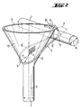
- the wire bracket designed as a quick connector consists of a bent piece of wire made of at least partially resilient metal between 2 and 8 mm diameter, the wire bracket with respect to one, for one-sided reception of the Molded dowels, half length with a radius greater than or equal to not radially widened diameter of an associated cast-in dowel, Primary turning between 90 ° and 180 ° with mirror symmetry to the bisector Is designed flat legs, each leg one, for one-sided Recording an associated reinforcing iron trained, substantially perpendicular for the primary turning bend, the secondary turning bend is between 90 ° and 360 °, with a radius greater than or equal to the diameter of the reinforcing iron and in each case one end, bent essentially perpendicular to the primary turning bend, in Angle between 30 ° and 90 ° angled, clip-on hook is formed, which in the radially outer end region of the radial expansion at the end of the casting anchor is designed to be non-positive.
- the pouring dowel is in the non-radially expanded part of the primary turn of the Wire bracket can be gripped radially on one side.
- the clip-in hooks of the legs spring into the radial expansion at the end detachable. Due to the radial expansion of the casting anchor clip-in hook of each leg and that, the not radially expanded part of the
- the wire bracket is a three-point primary turning bend securely fixed at the end of the cast-in dowel. Between the radial this is the expanded part of the cast-in dowel and the two secondary turning bends continuous reinforcing bars securely fixed with a positive fit.
- the secondary turning bend is advantageously between 90 ° and 180 °, as a result of which continuous reinforcing irons can be inserted radially on one side.
- the tertiary turn parallel to the primary turn is advantageous, further advantageous in Direction to the plane of symmetry, curved, whereby the reinforcing iron per leg additionally abuts the tertiary leg and the wire bracket is compact.
- the wire bracket 1 designed as a quick connector consists of a bent wire piece of diameter D and length L.
- Each leg 5, 5 ' is one end, perpendicular to the primary turning bend 3 and perpendicular to Secondary turning bend 6, 6 'bent, at an angle of 90 ° in the direction of Angle bisecting plane 4 angled, clipped hook 8, 8 'formed, which non-positively in a radially outer end region 9 of a conical end radial expansion 10 of the dowel 2 is compressed.
- Each leg 5, 5 ' is the end, perpendicular to the primary turning bend 3 and parallel to the secondary turning bend 6, 6 'curved, clip-in hook 8, 8' formed at an angle of 60 °, which is non-positive in the radially outer end region 9 of the conical end radial expansion 10 of the dowel 2 is compressed.
Landscapes
- Engineering & Computer Science (AREA)
- Architecture (AREA)
- Civil Engineering (AREA)
- Structural Engineering (AREA)
- Physics & Mathematics (AREA)
- Electromagnetism (AREA)
- Joining Of Building Structures In Genera (AREA)
- Reinforcement Elements For Buildings (AREA)
- Clamps And Clips (AREA)
Applications Claiming Priority (2)
| Application Number | Priority Date | Filing Date | Title |
|---|---|---|---|
| DE10108231A DE10108231A1 (de) | 2001-02-21 | 2001-02-21 | Schnellverbinder für Armierungseisen an Eingussdübel |
| DE10108231 | 2001-02-21 |
Publications (2)
| Publication Number | Publication Date |
|---|---|
| EP1234923A1 true EP1234923A1 (fr) | 2002-08-28 |
| EP1234923B1 EP1234923B1 (fr) | 2008-07-02 |
Family
ID=7674928
Family Applications (1)
| Application Number | Title | Priority Date | Filing Date |
|---|---|---|---|
| EP02405092A Expired - Lifetime EP1234923B1 (fr) | 2001-02-21 | 2002-02-08 | Raccord rapide pour barres d'armatures a un goujon rapporte par moulage |
Country Status (5)
| Country | Link |
|---|---|
| US (1) | US6832458B2 (fr) |
| EP (1) | EP1234923B1 (fr) |
| JP (1) | JP4288035B2 (fr) |
| AT (1) | ATE399909T1 (fr) |
| DE (2) | DE10108231A1 (fr) |
Families Citing this family (10)
| Publication number | Priority date | Publication date | Assignee | Title |
|---|---|---|---|---|
| US20060248843A1 (en) * | 2005-05-09 | 2006-11-09 | Alvaro Zapata | Foundation rebar hangers |
| US7314334B1 (en) * | 2006-08-03 | 2008-01-01 | Dayton Superior Corporation | Dowel bar assembly with snap fit side frames |
| US20090199504A1 (en) * | 2008-02-07 | 2009-08-13 | Tomarco Contractor Specialties, Inc. | Support structure for use with metal beams |
| US20100031607A1 (en) * | 2008-08-11 | 2010-02-11 | Oliva Michael G | Splice System for Fiber-Reinforced Polymer Rebars |
| US8413396B2 (en) * | 2009-08-11 | 2013-04-09 | Wisconsin Alumni Research Foundation | Splice system for connecting rebars in concrete assemblies |
| GB2504062A (en) * | 2012-06-12 | 2014-01-22 | Clifford Mark Burgin | Spiral device for catching and retaining a cable |
| GB201505217D0 (en) * | 2015-03-26 | 2015-05-13 | Gripple Ltd | Gripping arrangement |
| US9995035B1 (en) * | 2017-02-15 | 2018-06-12 | Columbia Insurance Company | Support for foundation strap |
| US10301825B1 (en) | 2017-11-28 | 2019-05-28 | Jason G. Uncapher | Rebar holster system |
| EP3748172A1 (fr) | 2019-06-07 | 2020-12-09 | Hilti Aktiengesellschaft | Procédé de renfort et clips d'ancrage appropriés |
Citations (6)
| Publication number | Priority date | Publication date | Assignee | Title |
|---|---|---|---|---|
| US3163266A (en) | 1961-01-23 | 1964-12-29 | United States Gypsum Co | Suspended ceiling construction and clip therefor |
| FR2033467A5 (fr) * | 1969-02-25 | 1970-12-04 | Matreno | |
| GB1405083A (en) * | 1973-03-30 | 1975-09-03 | Harke A | Masonry plug |
| US4000591A (en) * | 1975-08-04 | 1977-01-04 | Superior Concrete Accessories, Inc. | Holder adapted for supporting an anchor insert to be embedded in a concrete slab |
| US4388791A (en) | 1980-04-28 | 1983-06-21 | Anderson Frank H | Rebar tie |
| DE19813565A1 (de) * | 1998-03-27 | 1999-09-30 | Schoeck Bauteile Gmbh | Bauelement zur Schubbewehrung |
Family Cites Families (6)
| Publication number | Priority date | Publication date | Assignee | Title |
|---|---|---|---|---|
| US1119123A (en) * | 1913-05-31 | 1914-12-01 | George R Schoenthaler | Support and tie for concrete-reinforcing bars. |
| US1629485A (en) * | 1923-12-26 | 1927-05-24 | Cement Gun Company Inc | Holding clip for concrete reenforcement |
| US1835806A (en) * | 1929-06-24 | 1931-12-08 | Olmsted | Chair and spacer for concrete reenforcements |
| US4640063A (en) * | 1985-08-13 | 1987-02-03 | Henry Ayala | Reinforcing bar support clip |
| US5242249A (en) * | 1991-08-12 | 1993-09-07 | Mmi Products | Pre-cast panel lifting insert |
| US6019546A (en) * | 1998-08-31 | 2000-02-01 | Meadow-Burke Products | Support for load transfer device for concrete constructions |
-
2001
- 2001-02-21 DE DE10108231A patent/DE10108231A1/de not_active Withdrawn
-
2002
- 2002-02-08 AT AT02405092T patent/ATE399909T1/de active
- 2002-02-08 EP EP02405092A patent/EP1234923B1/fr not_active Expired - Lifetime
- 2002-02-08 DE DE50212420T patent/DE50212420D1/de not_active Expired - Lifetime
- 2002-02-19 JP JP2002041231A patent/JP4288035B2/ja not_active Expired - Fee Related
- 2002-02-20 US US10/079,787 patent/US6832458B2/en not_active Expired - Fee Related
Patent Citations (6)
| Publication number | Priority date | Publication date | Assignee | Title |
|---|---|---|---|---|
| US3163266A (en) | 1961-01-23 | 1964-12-29 | United States Gypsum Co | Suspended ceiling construction and clip therefor |
| FR2033467A5 (fr) * | 1969-02-25 | 1970-12-04 | Matreno | |
| GB1405083A (en) * | 1973-03-30 | 1975-09-03 | Harke A | Masonry plug |
| US4000591A (en) * | 1975-08-04 | 1977-01-04 | Superior Concrete Accessories, Inc. | Holder adapted for supporting an anchor insert to be embedded in a concrete slab |
| US4388791A (en) | 1980-04-28 | 1983-06-21 | Anderson Frank H | Rebar tie |
| DE19813565A1 (de) * | 1998-03-27 | 1999-09-30 | Schoeck Bauteile Gmbh | Bauelement zur Schubbewehrung |
Also Published As
| Publication number | Publication date |
|---|---|
| JP4288035B2 (ja) | 2009-07-01 |
| US20020112436A1 (en) | 2002-08-22 |
| EP1234923B1 (fr) | 2008-07-02 |
| DE50212420D1 (de) | 2008-08-14 |
| DE10108231A1 (de) | 2002-08-22 |
| US6832458B2 (en) | 2004-12-21 |
| ATE399909T1 (de) | 2008-07-15 |
| JP2002256625A (ja) | 2002-09-11 |
Similar Documents
| Publication | Publication Date | Title |
|---|---|---|
| US5878546A (en) | Concrete reinforcing bar connector | |
| US9279246B2 (en) | Twist on wire tie wall connection system and method | |
| DE102004021938B4 (de) | Leuchtstofflampen-Haltefeder | |
| DE102004006211B4 (de) | Verbindungsvorrichtung | |
| EP2067908B1 (fr) | Outil de fixation pour une tige de renfort | |
| EP1260751A2 (fr) | Collier de serrage, notamment raccord de tuyaux | |
| EP1234923A1 (fr) | Raccord rapide pour barres d'armatures a un goujon rapporte par moulage | |
| EP0275033A2 (fr) | Dispositif d'ancrage | |
| US6571528B1 (en) | Mechanical connector between headed studs and reinforcing steel | |
| DE102004006204B3 (de) | Trägeranbindung | |
| DE3346423A1 (de) | Rohrschelle | |
| KR100404425B1 (ko) | 쐐기형 원터치 철근 연결 장치 | |
| DE102019118722B4 (de) | Einschlagschelle | |
| CN216519035U (zh) | 一种用于纵杆和横杆固定的自锁式抱紧卡箍 | |
| US7162843B2 (en) | Bolts with connected anchor | |
| JP2003120029A (ja) | 鉄筋とセパレータの連結金物 | |
| CH703670B1 (de) | Abschalplattenhalter. | |
| AU781708B2 (en) | Connecting ferrule | |
| DE102006048999B3 (de) | Haltevorrichtung für Bauteile in einem Schacht | |
| KR200386855Y1 (ko) | 배관용 원터치 행거 | |
| US20060137286A1 (en) | Anchor for structural joints | |
| JP2000257262A (ja) | ボルト取付金具 | |
| JP3107191U (ja) | パイプ連結具 | |
| JPH08158540A (ja) | 鉄筋用継手装置 | |
| JP2023108701A (ja) | 吊り足場用根太の端部材 |
Legal Events
| Date | Code | Title | Description |
|---|---|---|---|
| PUAI | Public reference made under article 153(3) epc to a published international application that has entered the european phase |
Free format text: ORIGINAL CODE: 0009012 |
|
| AK | Designated contracting states |
Kind code of ref document: A1 Designated state(s): AT BE CH CY DE DK ES FI FR GB GR IE IT LI LU MC NL PT SE TR |
|
| AX | Request for extension of the european patent |
Free format text: AL;LT;LV;MK;RO;SI |
|
| 17P | Request for examination filed |
Effective date: 20030228 |
|
| AKX | Designation fees paid |
Designated state(s): AT CH DE FR GB IT LI |
|
| 17Q | First examination report despatched |
Effective date: 20061222 |
|
| GRAP | Despatch of communication of intention to grant a patent |
Free format text: ORIGINAL CODE: EPIDOSNIGR1 |
|
| GRAS | Grant fee paid |
Free format text: ORIGINAL CODE: EPIDOSNIGR3 |
|
| GRAA | (expected) grant |
Free format text: ORIGINAL CODE: 0009210 |
|
| AK | Designated contracting states |
Kind code of ref document: B1 Designated state(s): AT CH DE FR GB IT LI |
|
| REG | Reference to a national code |
Ref country code: GB Ref legal event code: FG4D Free format text: NOT ENGLISH |
|
| REG | Reference to a national code |
Ref country code: CH Ref legal event code: EP |
|
| REF | Corresponds to: |
Ref document number: 50212420 Country of ref document: DE Date of ref document: 20080814 Kind code of ref document: P |
|
| PLBE | No opposition filed within time limit |
Free format text: ORIGINAL CODE: 0009261 |
|
| STAA | Information on the status of an ep patent application or granted ep patent |
Free format text: STATUS: NO OPPOSITION FILED WITHIN TIME LIMIT |
|
| 26N | No opposition filed |
Effective date: 20090403 |
|
| PGFP | Annual fee paid to national office [announced via postgrant information from national office to epo] |
Ref country code: CH Payment date: 20120214 Year of fee payment: 11 Ref country code: FR Payment date: 20120221 Year of fee payment: 11 |
|
| PGFP | Annual fee paid to national office [announced via postgrant information from national office to epo] |
Ref country code: DE Payment date: 20120111 Year of fee payment: 11 |
|
| PGFP | Annual fee paid to national office [announced via postgrant information from national office to epo] |
Ref country code: IT Payment date: 20120221 Year of fee payment: 11 Ref country code: GB Payment date: 20120208 Year of fee payment: 11 |
|
| PGFP | Annual fee paid to national office [announced via postgrant information from national office to epo] |
Ref country code: AT Payment date: 20120126 Year of fee payment: 11 |
|
| REG | Reference to a national code |
Ref country code: CH Ref legal event code: PL |
|
| REG | Reference to a national code |
Ref country code: AT Ref legal event code: MM01 Ref document number: 399909 Country of ref document: AT Kind code of ref document: T Effective date: 20130228 |
|
| GBPC | Gb: european patent ceased through non-payment of renewal fee |
Effective date: 20130208 |
|
| PG25 | Lapsed in a contracting state [announced via postgrant information from national office to epo] |
Ref country code: AT Free format text: LAPSE BECAUSE OF NON-PAYMENT OF DUE FEES Effective date: 20130228 Ref country code: CH Free format text: LAPSE BECAUSE OF NON-PAYMENT OF DUE FEES Effective date: 20130228 Ref country code: LI Free format text: LAPSE BECAUSE OF NON-PAYMENT OF DUE FEES Effective date: 20130228 |
|
| REG | Reference to a national code |
Ref country code: FR Ref legal event code: ST Effective date: 20131031 |
|
| REG | Reference to a national code |
Ref country code: DE Ref legal event code: R119 Ref document number: 50212420 Country of ref document: DE Effective date: 20130903 |
|
| PG25 | Lapsed in a contracting state [announced via postgrant information from national office to epo] |
Ref country code: IT Free format text: LAPSE BECAUSE OF NON-PAYMENT OF DUE FEES Effective date: 20130208 |
|
| PG25 | Lapsed in a contracting state [announced via postgrant information from national office to epo] |
Ref country code: DE Free format text: LAPSE BECAUSE OF NON-PAYMENT OF DUE FEES Effective date: 20130903 Ref country code: GB Free format text: LAPSE BECAUSE OF NON-PAYMENT OF DUE FEES Effective date: 20130208 Ref country code: FR Free format text: LAPSE BECAUSE OF NON-PAYMENT OF DUE FEES Effective date: 20130228 |