EP1234792A2 - Saugring für Saugwalzen - Google Patents
Saugring für Saugwalzen Download PDFInfo
- Publication number
- EP1234792A2 EP1234792A2 EP02001559A EP02001559A EP1234792A2 EP 1234792 A2 EP1234792 A2 EP 1234792A2 EP 02001559 A EP02001559 A EP 02001559A EP 02001559 A EP02001559 A EP 02001559A EP 1234792 A2 EP1234792 A2 EP 1234792A2
- Authority
- EP
- European Patent Office
- Prior art keywords
- suction
- pot
- suction ring
- core
- ring according
- Prior art date
- Legal status (The legal status is an assumption and is not a legal conclusion. Google has not performed a legal analysis and makes no representation as to the accuracy of the status listed.)
- Granted
Links
- 239000000463 material Substances 0.000 claims abstract description 9
- 238000007789 sealing Methods 0.000 claims description 9
- 229910052782 aluminium Inorganic materials 0.000 claims description 4
- XAGFODPZIPBFFR-UHFFFAOYSA-N aluminium Chemical compound [Al] XAGFODPZIPBFFR-UHFFFAOYSA-N 0.000 claims description 4
- 229910000831 Steel Inorganic materials 0.000 claims description 3
- 229910052751 metal Inorganic materials 0.000 claims description 3
- 239000002184 metal Substances 0.000 claims description 3
- 238000005507 spraying Methods 0.000 claims description 3
- 239000010959 steel Substances 0.000 claims description 3
- 238000004519 manufacturing process Methods 0.000 description 3
- 238000005266 casting Methods 0.000 description 2
- 238000000034 method Methods 0.000 description 2
- 238000005553 drilling Methods 0.000 description 1
- 238000002347 injection Methods 0.000 description 1
- 239000007924 injection Substances 0.000 description 1
- 230000002093 peripheral effect Effects 0.000 description 1
Images

Classifications
-
- B—PERFORMING OPERATIONS; TRANSPORTING
- B65—CONVEYING; PACKING; STORING; HANDLING THIN OR FILAMENTARY MATERIAL
- B65H—HANDLING THIN OR FILAMENTARY MATERIAL, e.g. SHEETS, WEBS, CABLES
- B65H29/00—Delivering or advancing articles from machines; Advancing articles to or into piles
- B65H29/68—Reducing the speed of articles as they advance
- B65H29/686—Pneumatic brakes
-
- B—PERFORMING OPERATIONS; TRANSPORTING
- B65—CONVEYING; PACKING; STORING; HANDLING THIN OR FILAMENTARY MATERIAL
- B65H—HANDLING THIN OR FILAMENTARY MATERIAL, e.g. SHEETS, WEBS, CABLES
- B65H2401/00—Materials used for the handling apparatus or parts thereof; Properties thereof
- B65H2401/10—Materials
-
- B—PERFORMING OPERATIONS; TRANSPORTING
- B65—CONVEYING; PACKING; STORING; HANDLING THIN OR FILAMENTARY MATERIAL
- B65H—HANDLING THIN OR FILAMENTARY MATERIAL, e.g. SHEETS, WEBS, CABLES
- B65H2402/00—Constructional details of the handling apparatus
- B65H2402/60—Coupling, adapter or locking means
-
- B—PERFORMING OPERATIONS; TRANSPORTING
- B65—CONVEYING; PACKING; STORING; HANDLING THIN OR FILAMENTARY MATERIAL
- B65H—HANDLING THIN OR FILAMENTARY MATERIAL, e.g. SHEETS, WEBS, CABLES
- B65H2801/00—Application field
- B65H2801/03—Image reproduction devices
- B65H2801/21—Industrial-size printers, e.g. rotary printing press
Definitions
- the invention relates to a suction ring for suction rolls in arms of printing presses Braking of sheets, several suction rings being arranged across the width of the sheet conveying path are.
- Suction rolls in the delivery arms of printing machines are arranged directly in front of the delivery stack.
- the suction rings are rotated and they have openings on the surface in the form of slits or bores, to which suction air is applied.
- the over the sheet conveyed by the suction rings is drawn against the suction rings by the suction air, braked and tightened at the same time.
- the suction roll supports the proper one Sheet deposit.
- suction roll can be found in the document DE 33 464 13 A1.
- the suction ring according to this document coaxially receives the drive shaft and there are channels and others Air guides are provided through which the holes in the surface of the suction ring Suction air can be applied.
- the suction ring is made in one piece and usually made of Metal, preferably steel.
- a disadvantage of this suction ring is the large manufacturing effort for the introduction the air supply in the suction ring and the weight that the suction roller has a large Gives indolence.
- suction rings are also known which are made in one piece from plastic.
- a disadvantage of this plastic version is the great wear on the working and Sealing surface, which is provided on the face of the suction ring.
- the invention is based on the finding that the suction ring has two parts.
- the suction ring consists of a pot made of metal and a core with a lower weight than the pot. By using the spraying process to produce the core, its manufacture is easy. Plastic or aluminum is used as the material.
- the suction ring By using a material with great wear resistance for the pot the wear at the functional location of the suction ring (circumferential and sealing surface) is low. Due to the use of plastic or aluminum as the core, the suction ring has a total light weight. However, the suction ring still has the required wear resistance on the functional surfaces.
- the suction roll 4 includes a plurality of suction rings 8, which have the same structure.
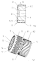
- the individual suction ring 8 (FIGS. 2 and 3) consists of a pot 8.1, which forms the outer functional surfaces (circumference and the end face designed as a sealing surface 13 for the suction air), and the core 8.2 located in the pot 8.1.
- the pot 8.1 is made of a material - preferably steel - with a high wear resistance.
- the core 8.2 consists of a material with a lower specific weight than the pot 8.1.
- the use of plastic as the core 8.2 has proven to be advantageous.
- the material of the core 8.2 enables it to be produced by injection or casting. This manufacture also lends itself to the shape of the core 8.2.
- the suction ring 8 is provided with a central bore 9.
- the suction ring 8 can also be designed according to the invention if the suction ring 8 via gear stages is rotated.
- Radial bores 10 are made in the circumference of the pot 8.1 and are distributed over the entire surface. However, slots can also be incorporated for the radial bores 10.
- the core 8.2 has non-continuous recesses 11 on its surface, which correspond to the radial bores 10 in the peripheral surface and on the sealing surface 13 to the through bores 12.
- bolts for securing against rotation 15 are also cast on, which are assigned to the bore for securing against rotation in the sealing surface 13 of the pot 8.1.
- the suction ring 8 is assigned to a suction air generator (not shown). The arc 7 is acted upon by suction air via the through bores 12, the recesses 11 and the radial bores 10.
- the suction ring 8 is produced by introducing the radial and through bore 10, 12, the bore to prevent rotation 14 and the central bore 9 into the pot 8.1.
- the core 8.2 is produced in the spraying process or in the casting process, as described constructively (see FIG. 3). Both parts are put together, ie the core 8.2 is pushed into the pot 8.1.
- the bore 14 and the bolt 15 (the bore 14 receives the bolt 15) must ensure that the radial bores 10 correspond to the recesses 11 and the recesses 11 in turn correspond to the through bores 12.
- the suction ring 8 is now functional and can be assigned to the suction roller 4. Pot 8.1 and core 8.2 are firmly connected.
Landscapes
- Engineering & Computer Science (AREA)
- Mechanical Engineering (AREA)
- Delivering By Means Of Belts And Rollers (AREA)
Abstract
Description
Die Erfindung geht von der Erkenntnis aus, den Saugring zweistückig auszuführen.
Der Saugring besteht aus einem Topf aus Metall und einem Kern mit geringerem Gewicht als der Topf.
Durch die Anwendung des Spritzverfahrens zur Erzeugung des Kernes ist dessen Herstellung einfach. Als Werkstoff kommt Kunststoff oder Aluminium zum Einsatz.
- Fig. 1
- schematische Darstellung (Ausschnitt) eines Bogenauslegers in Seitenansicht
- Fig. 2
- Schnitt durch den Saugring
- Fig. 3
- Saugring vor der Montage des Kernes in den Topf
Zur Saugwalze 4 gehören mehrere Saugringe 8, die einen gleichen Aufbau aufweisen. Der einzelne Saugring 8 (Fig. 2 und 3) besteht aus einem Topf 8.1, der die äußeren funktionellen Flächen (Umfang und die als Dichtfläche 13 für die Saugluft ausgebildete Stirnfläche) bildet, und dem im Topf 8.1 befindlichen Kern 8.2.
Der Topf 8.1 besteht aus einem Werkstoff - vorzugsweise aus Stahl - mit einer hohen Verschleißfestigkeit. Der Kern 8.2 besteht aus einem Werkstoff mit einem geringeren spezifischen Gewicht als der Topf 8.1. Als vorteilhaft hat sich die Verwendung von Kunststoff als Kern 8.2 erwiesen. Es ist jedoch auch denkbar, als Kern 8.2 Aluminium einzusetzen. Das Material des Kernes 8.2 ermöglicht seine Herstellung im Spritz- oder Gießverfahren. Diese Herstellung bietet sich durch die Form des Kernes 8.2 außerdem an.
Im Kern 8.2 sind weiterhin Bolzen zur Verdrehsicherung 15 angegossen, die der Bohrung zur Verdrehsicherung in der Dichtfläche 13 des Topfs 8.1 zugeordnet sind.
Über die Dichtfläche 13 ist der Saugring 8 einem nicht dargestellten Sauglufterzeuger zugeordnet. Über die Durchgangsbohrungen 12, die Ausnehmungen 11 und die Radialbohrungen 10 wird der Bogen 7 mit Saugluft beaufschlagt.
Der Saugring 8 wird hergestellt, indem in den Topf 8.1 die Radial- und Durchgangsbohrung 10,12 , die Bohrung zur Verdrehsicherheit 14 sowie die zentrische Bohrung 9 eingebracht wird.
Der Kern 8.2 wird im Spritzverfahren oder im Gießverfahren, wie konstruktiv beschrieben, hergestellt (sh. Fig. 3). Beide Teile werden zusammengefügt, d.h., der Kern 8.2 wird in den Topf 8.1 geschoben. Dabei muss durch die Bohrung 14 und den Bolzen 15 (die Bohrung 14 nimmt den Bolzen 15 auf) gesichert sein, dass die Radialbohrungen 10 zu den Ausnehmungen 11 und die Ausnehmungen 11 wiederum zu den Durchgangsbohrungen 12 korrespondieren. Nunmehr ist der Saugring 8 funktionsfähig und kann zur Saugwalze 4 zugeordnet werden. Topf 8.1 und Kern 8.2 sind dabei fest verbunden.
- 1
- Bogenausleger
- 2
- Auslegerstapel
- 3
- Vorderanschlag
- 4
- Saugwalze
- 5
- Auslegerkettenkreis
- 6
- Greiferwagen
- 7
- Bogen
- 8
- Saugring
- 8.1
- Topf
- 8.2
- Kern
- 9
- Bohrung
- 10
- Radialbohrung
- 11
- Ausnehmung
- 12
- Durchgangsbohrung
- 13
- Dichtfläche
- 14
- Bohrung zur Verdrehsicherung
- 15
- Bolzen zur Verdrehsicherung
Claims (8)
- Saugring für Saugwalzen in Bogenauslegern von Druckmaschinen, wobei die Saugwalze vor dem Auslegerstapel angeordnet und der rotativ bewegbare Saugring der Saugwalze mit Saugluft beaufschlagbar ist, dadurch gekennzeichnet,dass der Saugring (8) zweigeteilt ist undeinen die funktionellen Teile des Saugringes bildenden Topf (8.1) aus verschleißfestem Material sowieeinen vom Topf (8.1) aufnehmbaren Kern (8.2) aus einem Werkstoff mit geringerem Gewicht als der Topf (8.1) aufweist undder Kern (8.2) und der Topf (8.1) miteinander fest verbunden sind.
- Saugring nach Anspruch 1, dadurch gekennzeichnet, dass der Topf (8.1) aus Metall besteht.
- Saugring nach Anspruch 2, dadurch gekennzeichnet, dass der Topf (8.1) aus verschleißfestem Stahl besteht.
- Saugring nach Anspruch 1, dadurch gekennzeichnet, dass der Kern (8.2) aus Kunststoff besteht.
- Saugring nach Anspruch 1, dadurch gekennzeichnet, dass der Kern (8.2) aus Aluminium besteht.
- Saugring nach Anspruch 1, dadurch gekennzeichnet, dass der Kern (8.2) im Spritzverfahren herstellbar ist.
- Saugring nach Anspruch 1, dadurch gekennzeichnet, dass am Kern (8.2) Bolzen zur Verdrehsicherung (15) angeordnet sind, die Bohrungen zur Verdrehsicherung (14) in der Dichtfläche (13) des Topfes (8.1) angeordnet sind.
- Saugring nach Anspruch 1, dadurch gekennzeichnet, dass im Kern (8.2) nicht durchgehende Ausnehmungen (11) vorgesehen sind, die mit Radialbohrungen (10) im Umfang des Topfes (8.1) und mit den Durchgangsbohrungen (12) in der Dichtfläche des Topfes (8.1) korrespondieren.
Applications Claiming Priority (2)
| Application Number | Priority Date | Filing Date | Title |
|---|---|---|---|
| DE10109381 | 2001-02-27 | ||
| DE10109381A DE10109381A1 (de) | 2001-02-27 | 2001-02-27 | Saugring für Saugwalzen |
Publications (3)
| Publication Number | Publication Date |
|---|---|
| EP1234792A2 true EP1234792A2 (de) | 2002-08-28 |
| EP1234792A3 EP1234792A3 (de) | 2004-01-02 |
| EP1234792B1 EP1234792B1 (de) | 2005-04-06 |
Family
ID=7675634
Family Applications (1)
| Application Number | Title | Priority Date | Filing Date |
|---|---|---|---|
| EP02001559A Expired - Lifetime EP1234792B1 (de) | 2001-02-27 | 2002-01-23 | Saugring für Saugwalzen |
Country Status (2)
| Country | Link |
|---|---|
| EP (1) | EP1234792B1 (de) |
| DE (2) | DE10109381A1 (de) |
Family Cites Families (4)
| Publication number | Priority date | Publication date | Assignee | Title |
|---|---|---|---|---|
| GB1228575A (de) * | 1967-08-16 | 1971-04-15 | ||
| DD215060B3 (de) * | 1983-04-29 | 1992-12-10 | Kba Planeta Ag | Anordnung von saugringen in bogenbremsen von bogenauslegern |
| DE59500707D1 (de) * | 1994-07-22 | 1997-10-30 | Roland Man Druckmasch | Bogenbremse im Ausleger einer Druckmaschine |
| DE19834811C1 (de) * | 1998-08-01 | 1999-12-02 | Roland Man Druckmasch | Bremseinrichtung für Bogenmaterial in einer Druckmaschine |
-
2001
- 2001-02-27 DE DE10109381A patent/DE10109381A1/de not_active Withdrawn
-
2002
- 2002-01-23 EP EP02001559A patent/EP1234792B1/de not_active Expired - Lifetime
- 2002-01-23 DE DE50202676T patent/DE50202676D1/de not_active Expired - Lifetime
Also Published As
| Publication number | Publication date |
|---|---|
| EP1234792A3 (de) | 2004-01-02 |
| DE50202676D1 (de) | 2005-05-12 |
| DE10109381A1 (de) | 2002-09-05 |
| EP1234792B1 (de) | 2005-04-06 |
Similar Documents
| Publication | Publication Date | Title |
|---|---|---|
| EP0279394B1 (de) | Haltevorrichtung für das Aufbringen einer Hülse auf einen Zylinder | |
| EP0819550B1 (de) | Gummizylinderhülse, insbesondere für Offset-Rollenrotationsdruckmaschinen | |
| EP0085751A1 (de) | Offset-Bogen-Rotationsdruckmaschine | |
| DE2945821C2 (de) | Hydrodynamisches Wellenlager | |
| DE3530979A1 (de) | Radialkolbenmaschine | |
| DE2522657A1 (de) | Walze zur druckbehandlung von bahnfoermigen materialien | |
| DE3401634A1 (de) | Friktionsrollenbahn mit friktion zwischen laengswelle und querwellen | |
| DE2402206A1 (de) | Verfahren und vorrichtung zur herstellung eines hohlzylindrischen koerpers | |
| EP0943433B1 (de) | Druckwerk für eine Druckmaschine, insbesondere Offset-Rotationsmaschine | |
| EP1234792B1 (de) | Saugring für Saugwalzen | |
| DE1962247A1 (de) | Stuetz- und Antriebsrolle fuer Falschdrallspindeln einer Falschdrall-Kraeuselmaschine | |
| DE10296634B4 (de) | Entrindungswellenanordnung für eine Entrindungsmaschine | |
| DE102017116427A1 (de) | Antriebsrad für ein Kettenlaufwerk eines Kettenfahrzeugs | |
| DE3127506A1 (de) | Matrize fuer granulierpressen, insbesondere zum herstellen von futtermittelgranulaten | |
| DE2753284A1 (de) | Schmitzringverbindung zwischen zwei druckwerkszylindern | |
| DE4312123A1 (de) | Stator für Exzenterschneckenpumpen | |
| DE1561267B2 (de) | Walzenkoerper fuer schreibwalzen von schreib bzw rechen maschinen | |
| DE4431114A1 (de) | Bogenführender Trommelkörper für eine Druckmaschine | |
| DE3338965A1 (de) | Vorrichtung zum dehnen und/oder streichen einer bewegten bahn | |
| DE19616423C2 (de) | Einrichtung zum Wechseln von Bogenbremsen | |
| DE3840457C2 (de) | Angetriebene Auftragwalze | |
| EP1456032A1 (de) | Druckzylinder in form eines hohlzylinders aus metall | |
| DE10334839A1 (de) | Stickkopf für eine Stickmaschine | |
| DE4406143C2 (de) | Lagerung für Zylinder und Trommeln in Druckmaschinen | |
| DE202008004977U1 (de) | Hochdruckwalze |
Legal Events
| Date | Code | Title | Description |
|---|---|---|---|
| PUAI | Public reference made under article 153(3) epc to a published international application that has entered the european phase |
Free format text: ORIGINAL CODE: 0009012 |
|
| AK | Designated contracting states |
Kind code of ref document: A2 Designated state(s): AT BE CH CY DE DK ES FI FR GB GR IE IT LI LU MC NL PT SE TR |
|
| AX | Request for extension of the european patent |
Free format text: AL;LT;LV;MK;RO;SI |
|
| PUAL | Search report despatched |
Free format text: ORIGINAL CODE: 0009013 |
|
| AK | Designated contracting states |
Kind code of ref document: A3 Designated state(s): AT BE CH CY DE DK ES FI FR GB GR IE IT LI LU MC NL PT SE TR |
|
| AX | Request for extension of the european patent |
Extension state: AL LT LV MK RO SI |
|
| 17P | Request for examination filed |
Effective date: 20031113 |
|
| AKX | Designation fees paid |
Designated state(s): DE FR GB IT |
|
| GRAP | Despatch of communication of intention to grant a patent |
Free format text: ORIGINAL CODE: EPIDOSNIGR1 |
|
| GRAS | Grant fee paid |
Free format text: ORIGINAL CODE: EPIDOSNIGR3 |
|
| GRAA | (expected) grant |
Free format text: ORIGINAL CODE: 0009210 |
|
| AK | Designated contracting states |
Kind code of ref document: B1 Designated state(s): DE FR GB IT |
|
| REG | Reference to a national code |
Ref country code: GB Ref legal event code: FG4D Free format text: NOT ENGLISH |
|
| REG | Reference to a national code |
Ref country code: IE Ref legal event code: FG4D Free format text: LANGUAGE OF EP DOCUMENT: GERMAN |
|
| REF | Corresponds to: |
Ref document number: 50202676 Country of ref document: DE Date of ref document: 20050512 Kind code of ref document: P |
|
| GBT | Gb: translation of ep patent filed (gb section 77(6)(a)/1977) |
Effective date: 20050803 |
|
| PLBI | Opposition filed |
Free format text: ORIGINAL CODE: 0009260 |
|
| PLAX | Notice of opposition and request to file observation + time limit sent |
Free format text: ORIGINAL CODE: EPIDOSNOBS2 |
|
| 26 | Opposition filed |
Opponent name: MAN ROLAND DRUCKMASCHINEN AG Effective date: 20060105 |
|
| ET | Fr: translation filed | ||
| PLBB | Reply of patent proprietor to notice(s) of opposition received |
Free format text: ORIGINAL CODE: EPIDOSNOBS3 |
|
| PLCK | Communication despatched that opposition was rejected |
Free format text: ORIGINAL CODE: EPIDOSNREJ1 |
|
| PLBN | Opposition rejected |
Free format text: ORIGINAL CODE: 0009273 |
|
| STAA | Information on the status of an ep patent application or granted ep patent |
Free format text: STATUS: OPPOSITION REJECTED |
|
| 27O | Opposition rejected |
Effective date: 20070408 |
|
| PGFP | Annual fee paid to national office [announced via postgrant information from national office to epo] |
Ref country code: FR Payment date: 20120206 Year of fee payment: 11 |
|
| PGFP | Annual fee paid to national office [announced via postgrant information from national office to epo] |
Ref country code: GB Payment date: 20120120 Year of fee payment: 11 Ref country code: IT Payment date: 20120125 Year of fee payment: 11 |
|
| GBPC | Gb: european patent ceased through non-payment of renewal fee |
Effective date: 20130123 |
|
| REG | Reference to a national code |
Ref country code: FR Ref legal event code: ST Effective date: 20130930 |
|
| PG25 | Lapsed in a contracting state [announced via postgrant information from national office to epo] |
Ref country code: GB Free format text: LAPSE BECAUSE OF NON-PAYMENT OF DUE FEES Effective date: 20130123 Ref country code: FR Free format text: LAPSE BECAUSE OF NON-PAYMENT OF DUE FEES Effective date: 20130131 |
|
| PG25 | Lapsed in a contracting state [announced via postgrant information from national office to epo] |
Ref country code: IT Free format text: LAPSE BECAUSE OF NON-PAYMENT OF DUE FEES Effective date: 20130123 |
|
| PGFP | Annual fee paid to national office [announced via postgrant information from national office to epo] |
Ref country code: DE Payment date: 20150318 Year of fee payment: 14 |
|
| REG | Reference to a national code |
Ref country code: DE Ref legal event code: R081 Ref document number: 50202676 Country of ref document: DE Owner name: KOENIG & BAUER AG, DE Free format text: FORMER OWNER: KOENIG & BAUER AKTIENGESELLSCHAFT, 97080 WUERZBURG, DE |
|
| REG | Reference to a national code |
Ref country code: DE Ref legal event code: R119 Ref document number: 50202676 Country of ref document: DE |
|
| PG25 | Lapsed in a contracting state [announced via postgrant information from national office to epo] |
Ref country code: DE Free format text: LAPSE BECAUSE OF NON-PAYMENT OF DUE FEES Effective date: 20160802 |