EP1234734A1 - Dispositif de blocage de direction pour véhicule équipé d'une direction assistée électrique - Google Patents
Dispositif de blocage de direction pour véhicule équipé d'une direction assistée électrique Download PDFInfo
- Publication number
- EP1234734A1 EP1234734A1 EP02356038A EP02356038A EP1234734A1 EP 1234734 A1 EP1234734 A1 EP 1234734A1 EP 02356038 A EP02356038 A EP 02356038A EP 02356038 A EP02356038 A EP 02356038A EP 1234734 A1 EP1234734 A1 EP 1234734A1
- Authority
- EP
- European Patent Office
- Prior art keywords
- steering
- motor
- torque
- locking
- steering column
- Prior art date
- Legal status (The legal status is an assumption and is not a legal conclusion. Google has not performed a legal analysis and makes no representation as to the accuracy of the status listed.)
- Granted
Links
- 230000007246 mechanism Effects 0.000 claims description 30
- 230000000903 blocking effect Effects 0.000 claims description 27
- 238000001514 detection method Methods 0.000 claims description 12
- 238000012545 processing Methods 0.000 claims description 7
- 230000009471 action Effects 0.000 claims description 4
- 238000006386 neutralization reaction Methods 0.000 claims 1
- 230000008901 benefit Effects 0.000 description 3
- 238000006073 displacement reaction Methods 0.000 description 3
- 238000013461 design Methods 0.000 description 2
- 230000009347 mechanical transmission Effects 0.000 description 2
- 230000009466 transformation Effects 0.000 description 2
- 241001080024 Telles Species 0.000 description 1
- 240000008042 Zea mays Species 0.000 description 1
- 238000005259 measurement Methods 0.000 description 1
- 238000000034 method Methods 0.000 description 1
- 230000004048 modification Effects 0.000 description 1
- 238000012986 modification Methods 0.000 description 1
- 230000003472 neutralizing effect Effects 0.000 description 1
- 230000008569 process Effects 0.000 description 1
- 230000002747 voluntary effect Effects 0.000 description 1
Images
Classifications
-
- B—PERFORMING OPERATIONS; TRANSPORTING
- B62—LAND VEHICLES FOR TRAVELLING OTHERWISE THAN ON RAILS
- B62D—MOTOR VEHICLES; TRAILERS
- B62D5/00—Power-assisted or power-driven steering
- B62D5/04—Power-assisted or power-driven steering electrical, e.g. using an electric servo-motor connected to, or forming part of, the steering gear
-
- B—PERFORMING OPERATIONS; TRANSPORTING
- B60—VEHICLES IN GENERAL
- B60R—VEHICLES, VEHICLE FITTINGS, OR VEHICLE PARTS, NOT OTHERWISE PROVIDED FOR
- B60R25/00—Fittings or systems for preventing or indicating unauthorised use or theft of vehicles
- B60R25/01—Fittings or systems for preventing or indicating unauthorised use or theft of vehicles operating on vehicle systems or fittings, e.g. on doors, seats or windscreens
- B60R25/02—Fittings or systems for preventing or indicating unauthorised use or theft of vehicles operating on vehicle systems or fittings, e.g. on doors, seats or windscreens operating on the steering mechanism
Definitions
- the present invention relates, in general, to vehicles automobiles equipped with electric-type power steering. She is relates, more particularly, to a device for blocking the steering of such a vehicle, when it is not in use.
- Most motor vehicles are fitted with a steering lock, which is activated when the vehicle is not used, to serve as an anti-theft device by preventing the driving of the vehicle.
- the blocking of the steering system of a motor vehicle, equipped with a device intended for this purpose is usually carried out manual by the rotary drive of the steering wheel by the user, up to an angular position of engagement of this blocking device, which then performs a mechanical locking of the steering column. So, steering lock operation requires some effort manual, at a time when, usually, management no longer benefits from any assistance.
- the blocking of management requiring voluntary action on the part of the vehicle user, there is always a risk of forgetting to blocking, when the user leaves his vehicle, with the consequence an increased risk of theft of the vehicle concerned.
- the present invention aims to avoid these drawbacks, by providing a blocking device which, taking advantage of the specificity of a certain type of power steering, avoids the user to make an effort manual to lock the steering system, while avoiding the risk of being forgotten blocking device, this device ensuring automation of the maneuvering blocking.
- the invention essentially relates to a device steering lock, for motor vehicle equipped with a steering electrically assisted, this locking device comprising, on the one hand, a locking mechanism acting on the steering column, or on a other part of the steering system, and secondly, associated with the engine electric steering assistance, control means receiving signals from at least one triggering event detector and / or state of the vehicle, so as to control the electric assistance motor and to drive in rotation the steering column, by the action of this motor electric, until reaching a position in which the locking engages.
- the power steering electric is still automatically controlled, to rotate the steering column until a locking position of the steering by the locking mechanism.
- the trigger event detector is, for example, a vehicle door passage sensor from an unlocked state to a state Locked.
- Trigger event detection is preferably combined detection of vehicle states, such as zero vehicle speed and / or absence of the ignition key on the ignition lock, other conditions which can also be considered here.
- the detectors trigger event and states generate electrical signals, which are transmitted to the means of control where they are processed and combined, to control the rotation of the steering column by the engine electric assistance, by electrically supplying this motor with a sufficient power to steer the steered wheels while the vehicle do not move.
- the means of control above also receive a signal from a motor torque sensor, placed on the electric assistance motor and / or on the steering column or another part of management, and these means of control are provided for compare said signal with a predetermined threshold value corresponding to the minus a locking position of the steering column by the locking, and to stop, or not cause, the engine control electric assistance when the measured torque exceeds the threshold value.
- the torque sensor can be combined with an existing torsion bar on the steering column.
- the aforementioned control means receive, at instead of a signal from a torque sensor, a signal from a torque sensor steering position, such as an angular position sensor, and these means are provided to compare the signal from said position sensor with a predetermined value corresponding to at least one blocking position of the steering column by the locking mechanism, and to stop, or do not cause the electric assist motor to control when the detected position of the direction corresponds to a blocking position of this steering by the locking mechanism.
- a torque sensor or a torque sensor position
- a torque sensor offers additional possibilities, in particular to take in consideration of the possibility of the stop of a steering wheel of the vehicle against a physical obstacle, for example a curb, during the automatic steering lock process by the device of the invention.
- the device comprises, in addition to a torque sensor acting on the steering column, means detecting the increase in torque of the electric assistance motor, and processing means provided to analyze whether the increase in torque of this motor is simultaneous with the increase in torque of the resistive torque sensor, the electric assistance motor being controlled so that in the event of non-simultaneity the rise of the two couples, significant of the stop of a wheel vehicle manager against an obstacle, the engine is controlled in the other direction of rotation until reaching a steering lock position.
- the device comprises as before means of detection of the increase in torque of the electric assistance motor, and processing means provided to analyze whether the increase in torque of this engine is simultaneous with reaching a steering lock position, detected by detection of the steering position by means of the absolute position, the electric assistance motor being controlled so that in the event of a non-simultaneous increase in torque with the achievement of a steering lock position, significant of the stop of a steering wheel of the vehicle against an obstacle, the engine is controlled in the other direction of rotation until reaching a steering lock position.
- the electric assistance motor automatically controls the rotation of the steering column in the opposite direction to the movement initially engaged, to try to reach another angular position allowing locking.
- This additional provision gives the automatic operation of the direction with a view to blocking it, an almost certainty of success.
- control means are advantageously provided for stopping the electric assistance motor, therefore to interrupt the automatic steering maneuver, in the event of new detection of a rise in torque of the electric assistance motor not simultaneous with the rise in torque of the resistive torque sensor, or case of non-simultaneous increase in torque with reaching a position steering lock after reversing the direction of rotation of this motor.
- this device "ignores", at the time of each commissioning, what is the angular position of angular blocking the closer to the initial position of the steering column, and the engine electric assistance is started in an arbitrary direction of rotation, which does not necessarily correspond to the shortest angular displacement to reach one of the locking positions, defined by the locking.
- This operating mode can lead to consumption excessive and unnecessary electrical wear and tire wear on the wheels of the vehicle concerned.
- the control means belonging to the device of the invention can be provided for comparing the initial angular position of the steering column, that is to say its position at the moment of detection of the triggering event, with preset angular positions for locking the steering column by the locking mechanism, and to control the rotation of the electric assistance motor in a direction corresponding to the displacement shortest angle between the initial position and a blocking position.
- the device allows to automatically bring the column direction to the nearest blocking position, from the position of this column at the moment when the vehicle is left by its user, by limiting thus the wear of the tires of the vehicle and also the electric consumption linked to the operation of the device.
- the control means are provided for memorizing the initial angular position of the steering column, i.e. its position at the time of detection of the triggering event, position which is provided by an absolute angle sensor or relative, before the start of the steering column maneuver by the electric assistance motor to the locking position, and to control again the electric assistance motor, after neutralizing the locking mechanism, so as to operate the steering column in the opposite direction, and thus bring back this steering column in the initial angular position. So, after unlocking the steering, the wheels vehicle managers are automatically returned to their initial position, memorized, which can prevent the driver from being surprised when restarting the vehicle.
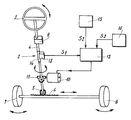
- the figure shows the usual elements of a direction 2 of motor vehicle, namely a driving wheel 3 linked to a column of steering 4, the far end of the steering wheel 3 of which carries a pinion 5 coming in taken with a rack 6, the two ends of the rack 6 being respectively linked, via links, to the two wheels guidelines 7 and 8 of the vehicle concerned.
- Steering 2 has a locking mechanism 9, with a function lock, which is arranged on the steering column 4, for example under the steering wheel 3. It can be, in particular but not necessarily, a mechanism 9 which is neutralized by the introduction of an ignition key into an ignition lock, which is activated when the ignition key is removed from its lock, or by another analogous electrically controlled system. In in all cases, the locking mechanism 9 ensures the rotation of the steering column 4 in at least one predetermined angular position.
- a electric assistance motor 10 with two directions of rotation, the shaft of which output is coupled to the steering column 4, via a mechanical transmission 11, so as to transmit an engine torque to it.
- the electric assistance motor 10 is controlled by a computer electronics 12; the latter receives, among other things, an electrical signal S1 originating a resistant torque sensor 13, placed on the steering column 4 and in particular associated with a torsion bar 14, inserted in the column of direction 4 between the locking mechanism 9 and the point of attack of the mechanical transmission 11 (not necessarily located at the location illustrated in drawing).
- a computer electronics 12 receives, among other things, an electrical signal S1 originating a resistant torque sensor 13, placed on the steering column 4 and in particular associated with a torsion bar 14, inserted in the column of direction 4 between the locking mechanism 9 and the point of attack of the mechanical transmission 11 (not necessarily located at the location illustrated in drawing).
- the electronic computer 12 also receives an electrical signal S2 from a trigger event detector 15, such as a passage of the vehicle doors from an unlocked state to a locked state, indicating that the vehicle has just been left by its driver or occupants.
- a trigger event detector 15 such as a passage of the vehicle doors from an unlocked state to a locked state, indicating that the vehicle has just been left by its driver or occupants.
- the same electronic computer 12 still receives a signal electric S3 from at least one detector 16 of states, such as zero speed vehicle and / or lack of the ignition key on the ignition lock, or other equivalent system, these states authorizing the intervention of the device to the instant of a trigger event detection.
- the computer 12, receiving and processing the electrical signals S2 and S3 from the trigger event and state detectors 15, 16, will generate, when these signals indicate that the vehicle has left, a command from the electric assistance motor 10 until the steering 2 is blocked by the locking mechanism 9, this according to a fully automatic.
- the electric motor assistance 10 is powered to rotate in a determined direction of rotation, and with sufficient power to rotate the column of direction 4 and rotate the two steered wheels 7 and 8.
- the rotation of the steering column 4 will stop as soon as the engine torque required for this rotation, exceeds a threshold value corresponding to the stop of the locking mechanism 9, this torque threshold value being defined at prior to the design of the steering system.
- Relative information at the instantaneous torque comes from the torque sensor 13, in the form of the signal S1 brought to the computer 12, which performs the processing.
- the computer 12 analyzes the increase in torque of the engine. electric assistance 10, measured by the fall in speed of this motor 10, in comparing it to the increase in torque of the torque sensor 13. If the two mounted in pairs are simultaneous, it is accepted that the first "obstacle” encountered is the stop of the locking mechanism 9, so that the column of direction 4 has indeed reached a blocking position by this mechanism, and the electric assistance motor 10 is then automatically stopped. Through against, a non-simultaneity of the two couples, here compared, indicates that a steerable wheel 7 or 8 has hit an obstacle, such as a curb, during its pivoting and before it could even be reaches an angular position for locking the steering column 4. The computer 12 then controls the electric assistance motor 10 in the direction opposite of rotation, to move the wheel 7 or 8 away from the obstacle encountered, and bring the steering column 4 to another blocking position which should be reached without encountering another obstacle.
- the means at the origin of the signal S1 would be a position or displacement sensor, giving the instantaneous position of the direction 2
- the significant increase in torque of the electric motor assistance 10 measured for example by the fall in its speed or by the voltage drop across this motor, is not simultaneous with reaching from a steering lock position 2
- the calculator 12 controls the electric assistance motor 10 in the opposite direction of rotation, to move the wheel 7 or 8 away from the obstacle encountered, and bring the direction 2 towards another blocking position which should be reached without meet obstacle.
- the steering lock device is applicable to any motor vehicle fitted with electric power steering, a steering column locking mechanism (or a locking system locking acting on another part of the steering system), and a automatic door locking / unlocking system.
Landscapes
- Engineering & Computer Science (AREA)
- Mechanical Engineering (AREA)
- Chemical & Material Sciences (AREA)
- Combustion & Propulsion (AREA)
- Transportation (AREA)
- Steering Control In Accordance With Driving Conditions (AREA)
- Lock And Its Accessories (AREA)
- Power Steering Mechanism (AREA)
Abstract
Description
- En premier lieu, elle offre à l'utilisateur la possibilité de ne plus avoir à fournir d'effort manuel pour bloquer le système de direction, puisque l'assistance électrique de cette direction est mise à profit pour faire tourner la colonne de direction jusqu'à la position de verrouillage, de sorte que le « confort » est augmenté. A cet égard, on notera que l'intervention d'une direction assistée électrique pour une telle fonction ne pose aucun problème, même lorsque le moteur thermique du véhicule est à l'arrêt (tel ne serait pas le cas pour une direction assistée hydraulique, qui nécessiterait le fonctionnement d'une pompe entraínée par le moteur thermique).
- L'automaticité du dispositif proposé, doté d'une « intelligence », rend impossible tout oubli de blocage de la direction, de la part de l'utilisateur du véhicule, ce qui augmente la sécurité en réduisant les risques de vol du véhicule.
- Le système possède une structure simple et économique. D'une part, il peut utiliser des capteurs et détecteurs, et un calculateur, déjà existants sur le véhicule. D'autre part, il ne nécessite aucune transformation de la direction du véhicule, et il utilise le mécanisme classique de verrouillage de la colonne de direction, ou d'une autre partie du système de direction, ce mécanisme ne nécessitant pas d'être modifié ou adapté.
- en utilisant tout moyen de mesure du couple, non nécessairement un capteur de couple associé à une barre de torsion ;
- en contrôlant le fonctionnement du dispositif à l'aide d'un capteur de position de la direction, par exemple un capteur de position angulaire, en remplacement ou en complément du capteur de couple ;
- en détectant et prenant en compte, pour autoriser le fonctionnement du dispositif, des états du véhicule autres que ceux envisagés plus haut ;
- en assignant au calculateur d'autres fonctions complémentaires, pour un fonctionnement plus affiné du dispositif ;
- en appliquant le dispositif à des véhicules dont le mécanisme de verrouillage n'est pas nécessairement neutralisé ou activé par une clé de contact, mais peut aussi l'être par tout autre moyen, tel qu'une carte codée à introduire ou à retirer ;
- en destinant le dispositif à une direction dans laquelle le mécanisme de verrouillage occupe une position quelconque sur le système de direction, non nécessairement sur la colonne de direction, ce mécanisme de verrouillage pouvant même être placé sur le moteur d'assistance ;
- en appliquant le dispositif à des directions assistées électriques de toutes conceptions, quel que soit notamment le point d'action du moteur électrique d'assistance sur le système de direction, ce point pouvant être situé sur la colonne de direction, sur le pignon ou sur la crémailère.
Claims (12)
- Dispositif de blocage de direction pour véhicule automobile équipé d'une direction assistée électrique, caractérisé en ce qu'il comprend, d'une part, un mécanisme de verrouillage (9) agissant sur la colonne de direction (4), ou sur une autre partie du système de direction (2), et d'autre part, associés au moteur électrique d'assistance (10) de la direction (2), des moyens de contrôle (12) recevant des signaux (S2, S3) issus d'au moins un détecteur (15, 16) d'événement déclencheur et/ou d'états du véhicule, de manière à commander le moteur électrique d'assistance (10) et à entraíner en rotation la colonne de direction (4), par l'action de ce moteur électrique (10), jusqu'à atteindre une position dans laquelle le mécanisme de verrouillage (9) s'enclenche.
- Dispositif de blocage de direction selon la revendication 1, caractérisé en ce que le détecteur d'événement déclencheur est un détecteur (15) de passage des portières du véhicule d'un état déverrouillé à un état verrouillé.
- Dispositif de blocage de direction selon la revendication 1 ou 2, caractérisé en ce que le détecteur d'états du véhicule est un détecteur (16) de vitesse nulle du véhicule et/ou d'absence de clé de contact sur la serrure de contact.
- Dispositif de blocage de direction selon l'une quelconque des revendications 1 à 3, caractérisé en ce que les moyens de contrôle (12) reçoivent aussi un signal (S1) issu d'un capteur de couple moteur (13), placé sur le moteur électrique d'assistance (10) et/ou sur la colonne de direction (4), et en ce que ces moyens de contrôle (12) sont prévus pour comparer ledit signal (S1) à une valeur de seuil prédéterminée correspondant à une position de blocage de la colonne de direction (4) par le mécanisme de verrouillage (9), et pour arrêter, ou ne pas provoquer, la commande de moteur électrique d'assistance (10) lorsque le couple mesuré dépasse la valeur de seuil.
- Dispositif de blocage de direction selon la revendication 4, caractérisé en ce que le capteur de couple (13) est associé à une barre de torsion (14) existante sur la colonne de direction (4).
- Dispositif de blocage de direction selon l'une quelconque des revendications 1 à 3, caractérisé en ce que les moyens de contrôle (12) reçoivent un signal issu d'un capteur de position de la direction (2), tel qu'un capteur de position angulaire, et en ce que ces moyens de contrôle (12) sont prévus pour comparer le signal issu dudit capteur de position à une valeur prédéterminée correspondant à au moins une position de blocage de la colonne de direction (4) par le mécanisme de verrouillage (9) et pour arrêter, ou ne pas provoquer, la commande du moteur électrique d'assistance (10) lorsque la position détectée de la direction (2) correspond à une position de blocage de cette direction (2) par le mécanisme de verrouillage (9).
- Dispositif de blocage de direction selon la revendication 4 ou 5, caractérisé en ce qu'il comprend, outre un capteur (13) du couple s'exerçant sur la colonne de direction (4), des moyens de détection de la montée en couple du moteur électrique d'assistance (10), et des moyens de traitement (12) prévus pour analyser si la montée en couple de ce moteur (10) est simultanée à la montée en couple du capteur (13) de couple résistant, le moteur électrique d'assistance (10) étant piloté de telle sorte qu'en cas de non-simultanéité de la montée des deux couples, significative de la butée d'une roue directrice (7,8) du véhicule contre un obstacle, le moteur (10) est commandé dans l'autre sens de rotation jusqu'à atteindre une position de verrouillage de la direction (2).
- Dispositif de blocage de direction selon l'une quelconque des revendications 1 à 6, caractérisé en ce qu'il comprend des moyens de détection de la montée en couple du moteur électrique d'assistance (10), et des moyens de traitement (12) prévus pour analyser si la montée en couple de ce moteur (10) est simultanée à l'atteinte d'une position de blocage de la direction (2), constatée par détection de la position de la direction (2) au moyen d'un capteur de position absolue, le moteur électrique d'assistance (10) étant piloté de telle sorte qu'en cas de non-simultanéité de la montée en couple avec l'atteinte d'une position de blocage de la direction (2), significative de la butée d'une roue directrice (7, 8) du véhicule contre un obstacle, le moteur (10) est commandé dans l'autre sens de rotation jusqu'à atteindre une position de verrouillage de la direction (2).
- Dispositif de blocage de direction selon la revendication 7 ou 8, caractérisé en ce que les moyens de commande (12) sont prévus pour arrêter le moteur électrique d'assistance (10), donc pour interrompre la manoeuvre automatique de la direction (2), en cas de nouvelle détection d'une montée en couple du moteur électrique d'assistance (10) non simultanée à la montée en couple du capteur (13) de couple, ou en cas de non-simultanéité de cette montée en couple avec l'atteinte d'une position de blocage de la direction, après inversion du sens de rotation de ce moteur (10).
- Dispositif de blocage de direction selon l'une quelconque des revendications 1 à 9, pour véhicule automobile équipé d'un capteur de position angulaire absolue de la colonne de direction (4), caractérisé en ce que les moyens de contrôle (12) sont prévus pour comparer la position angulaire initiale de la colonne de direction (4), c'est-à-dire sa position à l'instant de la détection de l'événement déclencheur, avec des positions angulaires de blocage préétablies de la colonne de direction (4) par le mécanisme de verrouillage (9), et pour commander la mise en rotation du moteur électrique d'assistance (10) dans un sens correspondant au déplacement angulaire le plus court entre la position initiale et une position de blocage.
- Dispositif de blocage de direction selon l'une quelconque des revendications 1 à 10, caractérisé en ce que les moyens de commande (12) sont prévus pour mémoriser la position angulaire initiale de la colonne de direction (4), c'est-à-dire la position à l'instant de la détection de l'événement déclencheur, position qui est fournie par un capteur d'angle absolu ou relatif, avant le début de la manoeuvre de la colonne de direction (4) par le moteur électrique d'assistance (10) vers la position de blocage, et pour commander à nouveau le moteur électrique d'assistance (10), après neutralisation du mécanisme de verrouillage (9), de manière à manoeuvrer la colonne de direction (4) dans le sens inverse, et ainsi ramener cette colonne de direction (4) dans la position angulaire initiale.
- Dispositif de blocage de direction selon l'une quelconque des revendications 1 à 11, caractérisé en ce que les moyens de contrôle, intervenant pour commander le moteur électrique d'assistance (10) en recevant et en traitant les signaux (S1, S2, S3) des détecteurs d'événement déclencheur et d'états du véhicule, et du capteur (13) de couple ou de position, sont constitués par un calculateur électronique (12).
Applications Claiming Priority (2)
| Application Number | Priority Date | Filing Date | Title |
|---|---|---|---|
| FR0102671A FR2821312B1 (fr) | 2001-02-27 | 2001-02-27 | Dispositif de blocage de direction, pour vehicule equipe d'une direction assistee electrique |
| FR0102671 | 2001-02-27 |
Publications (2)
| Publication Number | Publication Date |
|---|---|
| EP1234734A1 true EP1234734A1 (fr) | 2002-08-28 |
| EP1234734B1 EP1234734B1 (fr) | 2005-06-15 |
Family
ID=8860506
Family Applications (1)
| Application Number | Title | Priority Date | Filing Date |
|---|---|---|---|
| EP20020356038 Expired - Lifetime EP1234734B1 (fr) | 2001-02-27 | 2002-02-26 | Dispositif de blocage de direction pour véhicule équipé d'une direction assistée électrique |
Country Status (3)
| Country | Link |
|---|---|
| EP (1) | EP1234734B1 (fr) |
| DE (1) | DE60204609T2 (fr) |
| FR (1) | FR2821312B1 (fr) |
Cited By (10)
| Publication number | Priority date | Publication date | Assignee | Title |
|---|---|---|---|---|
| US6857496B2 (en) * | 2002-09-03 | 2005-02-22 | Trw Inc. | Vehicle steering apparatus with anti-steer security device |
| DE102004020513A1 (de) * | 2004-04-26 | 2005-11-10 | Lämmle, Knud | Lenksperre |
| DE10393313B4 (de) * | 2002-09-26 | 2008-03-13 | Jtekt Europe S.A.S. | Diebstahlsicherungsvorrichtung für Kraftfahrzeuge mit hydraulischer Servolenkung |
| DE102010028101A1 (de) * | 2010-04-22 | 2011-10-27 | Zf Lenksysteme Gmbh | Verfahren zum Blockieren eines Lenksystems |
| WO2012062548A1 (fr) * | 2010-11-08 | 2012-05-18 | Robert Bosch Gmbh | Dispositif de direction pour un véhicule automobile et procédé pour le blocage d'un dispositif de direction |
| EP2476593A1 (fr) * | 2011-01-13 | 2012-07-18 | Valeo Sicherheitssysteme GmbH | Procédé de protection contre le vol d'un vehicule automobile |
| DE102011052123A1 (de) * | 2011-07-26 | 2013-01-31 | Zf Lenksysteme Gmbh | Elektrische servolenkung |
| FR3006277A1 (fr) * | 2013-06-04 | 2014-12-05 | Jtekt Europe Sas | Utilisation d’un moteur d’assistance de direction pour simuler une butee de fin de course de ladite direction |
| WO2021032303A1 (fr) * | 2019-08-22 | 2021-02-25 | Thyssenkrupp Presta Ag | Procédé de commande du verrouillage de direction d'un système de direction à commande électrique d'un véhicule automobile |
| CN116133929A (zh) * | 2020-07-28 | 2023-05-16 | 捷太格特欧洲公司 | 用于辅助驾驶员进入和离开车辆的系统 |
Families Citing this family (10)
| Publication number | Priority date | Publication date | Assignee | Title |
|---|---|---|---|---|
| DE10151010A1 (de) * | 2001-10-16 | 2003-04-17 | Volkswagen Ag | Kraftfahrzeug mit einer Lenkradverriegelung |
| FR2837445B1 (fr) * | 2002-03-25 | 2004-06-11 | Soc Mecanique Irigny | Dispositif de deblocage de direction, pour vehicule equipe d'une direction assistee electrique |
| DE102005050246B4 (de) * | 2005-10-20 | 2016-06-09 | Volkswagen Ag | Lenkungsverriegelungssystem |
| DE102006001357A1 (de) * | 2006-01-11 | 2007-07-12 | Zf Lenksysteme Gmbh | Lenksystem |
| DE102006056042B4 (de) * | 2006-11-28 | 2018-06-14 | Volkswagen Ag | System zur Verriegelung und Freigabe einer elektromechanischen Lenkung |
| DE102009057150B4 (de) * | 2009-12-05 | 2020-06-04 | Volkswagen Ag | Elektromechanische Lenkung |
| DE102010002567A1 (de) * | 2010-03-04 | 2011-09-08 | Zf Lenksysteme Gmbh | Elektrische Lenkradverriegelung |
| FR2965238B1 (fr) | 2010-09-28 | 2013-06-14 | Jtekt Europe Sas | Direction assistee electrique a double vis sans fin |
| DE102010048684B4 (de) | 2010-10-16 | 2021-01-14 | Volkswagen Ag | Elektrisch verriegelbare Fahrzeuglenkung |
| DE102020212639A1 (de) | 2020-10-07 | 2022-04-07 | Volkswagen Aktiengesellschaft | Verfahren zur Erkennung einer Lenkungsblockade bei einem Fahrzeug sowie Fahrzeug mit Lenkungsblockade-Erkennungsfunktion |
Citations (4)
| Publication number | Priority date | Publication date | Assignee | Title |
|---|---|---|---|---|
| DE4303485A1 (de) * | 1993-02-06 | 1994-08-11 | Teves Gmbh Alfred | Kraftfahrzeug mit Lenkradschloß |
| EP0630800A1 (fr) * | 1993-06-21 | 1994-12-28 | Valeo Electronique | Dispositif de direction assistée électrique à verrou de colonne de direction |
| DE19601827A1 (de) * | 1996-01-19 | 1997-07-24 | Bosch Gmbh Robert | Lenksystem für ein Kraftfahrzeug |
| FR2793749A1 (fr) * | 1999-05-17 | 2000-11-24 | Lemforder Nacam Sa | Dispositif de securite contre le vol d'un vehicule automobile |
-
2001
- 2001-02-27 FR FR0102671A patent/FR2821312B1/fr not_active Expired - Fee Related
-
2002
- 2002-02-26 EP EP20020356038 patent/EP1234734B1/fr not_active Expired - Lifetime
- 2002-02-26 DE DE2002604609 patent/DE60204609T2/de not_active Expired - Lifetime
Patent Citations (4)
| Publication number | Priority date | Publication date | Assignee | Title |
|---|---|---|---|---|
| DE4303485A1 (de) * | 1993-02-06 | 1994-08-11 | Teves Gmbh Alfred | Kraftfahrzeug mit Lenkradschloß |
| EP0630800A1 (fr) * | 1993-06-21 | 1994-12-28 | Valeo Electronique | Dispositif de direction assistée électrique à verrou de colonne de direction |
| DE19601827A1 (de) * | 1996-01-19 | 1997-07-24 | Bosch Gmbh Robert | Lenksystem für ein Kraftfahrzeug |
| FR2793749A1 (fr) * | 1999-05-17 | 2000-11-24 | Lemforder Nacam Sa | Dispositif de securite contre le vol d'un vehicule automobile |
Cited By (19)
| Publication number | Priority date | Publication date | Assignee | Title |
|---|---|---|---|---|
| US6857496B2 (en) * | 2002-09-03 | 2005-02-22 | Trw Inc. | Vehicle steering apparatus with anti-steer security device |
| DE10393313B4 (de) * | 2002-09-26 | 2008-03-13 | Jtekt Europe S.A.S. | Diebstahlsicherungsvorrichtung für Kraftfahrzeuge mit hydraulischer Servolenkung |
| DE102004020513A1 (de) * | 2004-04-26 | 2005-11-10 | Lämmle, Knud | Lenksperre |
| DE102010028101A1 (de) * | 2010-04-22 | 2011-10-27 | Zf Lenksysteme Gmbh | Verfahren zum Blockieren eines Lenksystems |
| WO2012062548A1 (fr) * | 2010-11-08 | 2012-05-18 | Robert Bosch Gmbh | Dispositif de direction pour un véhicule automobile et procédé pour le blocage d'un dispositif de direction |
| CN103476643A (zh) * | 2011-01-13 | 2013-12-25 | 法雷奥安全系统有限责任公司 | 用于防止机动车辆被盗的方法 |
| WO2012095452A1 (fr) * | 2011-01-13 | 2012-07-19 | Valeo Sicherheitssysteme Gmbh | Procede de protection contre le vol d'un vehicule automobile |
| EP2476593A1 (fr) * | 2011-01-13 | 2012-07-18 | Valeo Sicherheitssysteme GmbH | Procédé de protection contre le vol d'un vehicule automobile |
| DE102011052123A1 (de) * | 2011-07-26 | 2013-01-31 | Zf Lenksysteme Gmbh | Elektrische servolenkung |
| CN105324291B (zh) * | 2013-06-04 | 2017-09-22 | 捷太格特欧洲公司 | 使用动力转向电机模拟所述转向的行程终端止动器 |
| WO2014195625A3 (fr) * | 2013-06-04 | 2015-04-16 | Jtekt Europe | Utilisation d'un moteur d'assistance de direction pour simuler une butée de fin de course de ladite direction |
| CN105324291A (zh) * | 2013-06-04 | 2016-02-10 | 捷太格特欧洲公司 | 使用动力转向电机模拟所述转向的行程终端止动器 |
| FR3006277A1 (fr) * | 2013-06-04 | 2014-12-05 | Jtekt Europe Sas | Utilisation d’un moteur d’assistance de direction pour simuler une butee de fin de course de ladite direction |
| US9950735B2 (en) | 2013-06-04 | 2018-04-24 | Jtekt Europe | Use of a power-steering motor to simulate an end-of-travel stop for said steering |
| WO2021032303A1 (fr) * | 2019-08-22 | 2021-02-25 | Thyssenkrupp Presta Ag | Procédé de commande du verrouillage de direction d'un système de direction à commande électrique d'un véhicule automobile |
| CN114206688A (zh) * | 2019-08-22 | 2022-03-18 | 蒂森克虏伯普利斯坦股份公司 | 用于控制机动车辆的线控转向系统的转向锁定的方法 |
| CN114206688B (zh) * | 2019-08-22 | 2024-03-29 | 蒂森克虏伯普利斯坦股份公司 | 用于控制机动车辆的线控转向系统的转向锁定的方法 |
| US12097910B2 (en) | 2019-08-22 | 2024-09-24 | Thyssenkrupp Presta Ag | Method for controlling steering locking of a steer-by-wire steering system of a motor vehicle |
| CN116133929A (zh) * | 2020-07-28 | 2023-05-16 | 捷太格特欧洲公司 | 用于辅助驾驶员进入和离开车辆的系统 |
Also Published As
| Publication number | Publication date |
|---|---|
| DE60204609D1 (de) | 2005-07-21 |
| DE60204609T2 (de) | 2006-05-11 |
| EP1234734B1 (fr) | 2005-06-15 |
| FR2821312B1 (fr) | 2003-05-09 |
| FR2821312A1 (fr) | 2002-08-30 |
Similar Documents
| Publication | Publication Date | Title |
|---|---|---|
| EP1234734B1 (fr) | Dispositif de blocage de direction pour véhicule équipé d'une direction assistée électrique | |
| FR2931753A1 (fr) | Procede et dispositif destines a faire fonctionner un vehicule automobile a l'aide d'un systeme de direction et systeme de direction en comportant application | |
| FR2715353A1 (fr) | Dispositif de sélection pour appareil de commande automatique d'une boîte de vitesses d'automobile. | |
| WO2012022871A2 (fr) | Sécurisation du couple d'assistance par un estimateur d'effort sur la crémaillère | |
| WO2003080406A2 (fr) | Dispositif de déblocage de direction, pour véhicule équipé d'une direction assistée électrique | |
| EP2476593B1 (fr) | Procédé de protection contre le vol d'un vehicule automobile | |
| WO2022023657A1 (fr) | Système d'assistance à l'installation et la désinstallation d'un conducteur dans un véhicule | |
| EP1937535B1 (fr) | Systeme d'aide a la manoeuvre pour un vehicule automobile | |
| EP1027239A1 (fr) | Systeme de freinage et vehicule automobile comportant un dispositif de regulation automatique de la distance | |
| FR2810614A1 (fr) | Direction assistee electrique pour vehicule automobile | |
| EP2663474A1 (fr) | Procede de commande automatique de l'antivol electrique de colonne de direction d'un vehicule automobile | |
| EP1935739B1 (fr) | Procédé d'automatisation de braquage des roues d'un véhicule automobile lors d'une sortie de ce véhicule d'une place de parking, et système associé | |
| WO2016009123A1 (fr) | Procede de commande de la position angulaire du volant d'un vehicule et vehicule associe | |
| JP2006256482A (ja) | 車両の操舵装置 | |
| JP2009096427A (ja) | ステアリング装置 | |
| FR2789962A1 (fr) | Procede et dispositif de commande du couple d'assistance applique au mecanisme de direction d'un vehicule automobile | |
| FR2861045A1 (fr) | Vehicule automobile a conduite assistee en situation de survirage | |
| FR2873646A1 (fr) | Procede de limitation des pertes d'assistance sur une direction assistee de vehicule automobile | |
| FR3128676A1 (fr) | Procédé de commande du verrouillage en position de stationnement d'une transmission d'un véhicule automobile | |
| FR2788734A1 (fr) | Systeme d'entrainement et procede de commande d'un tel systeme | |
| EP2834131B1 (fr) | Procede de commande du moteur de direction assistee electrique, dispositif correspondant, direction assistee et vehicule comprenant ledit dispositif | |
| WO2009083369A1 (fr) | Procede de coupure de l'assistance de direction d'un vehicule | |
| EP1234747A1 (fr) | Ensemble de direction assistée électrique pour véhicule et procédé de commande associé | |
| WO2025149556A1 (fr) | Unité de contrôle électronique pour système de commande de freinage | |
| WO2002058986A1 (fr) | Systeme d'assistance de direction electrique |
Legal Events
| Date | Code | Title | Description |
|---|---|---|---|
| PUAI | Public reference made under article 153(3) epc to a published international application that has entered the european phase |
Free format text: ORIGINAL CODE: 0009012 |
|
| AK | Designated contracting states |
Kind code of ref document: A1 Designated state(s): AT BE CH CY DE DK ES FI FR GB GR IE IT LI LU MC NL PT SE TR |
|
| AX | Request for extension of the european patent |
Free format text: AL;LT;LV;MK;RO;SI |
|
| 17P | Request for examination filed |
Effective date: 20030120 |
|
| AKX | Designation fees paid |
Designated state(s): DE ES GB IT SE |
|
| 17Q | First examination report despatched |
Effective date: 20031015 |
|
| GRAP | Despatch of communication of intention to grant a patent |
Free format text: ORIGINAL CODE: EPIDOSNIGR1 |
|
| GRAS | Grant fee paid |
Free format text: ORIGINAL CODE: EPIDOSNIGR3 |
|
| GRAA | (expected) grant |
Free format text: ORIGINAL CODE: 0009210 |
|
| AK | Designated contracting states |
Kind code of ref document: B1 Designated state(s): DE ES GB IT SE |
|
| PG25 | Lapsed in a contracting state [announced via postgrant information from national office to epo] |
Ref country code: IT Free format text: LAPSE BECAUSE OF FAILURE TO SUBMIT A TRANSLATION OF THE DESCRIPTION OR TO PAY THE FEE WITHIN THE PRESCRIBED TIME-LIMIT;WARNING: LAPSES OF ITALIAN PATENTS WITH EFFECTIVE DATE BEFORE 2007 MAY HAVE OCCURRED AT ANY TIME BEFORE 2007. THE CORRECT EFFECTIVE DATE MAY BE DIFFERENT FROM THE ONE RECORDED. Effective date: 20050615 Ref country code: GB Free format text: LAPSE BECAUSE OF FAILURE TO SUBMIT A TRANSLATION OF THE DESCRIPTION OR TO PAY THE FEE WITHIN THE PRESCRIBED TIME-LIMIT Effective date: 20050615 |
|
| REG | Reference to a national code |
Ref country code: GB Ref legal event code: FG4D Free format text: NOT ENGLISH |
|
| REF | Corresponds to: |
Ref document number: 60204609 Country of ref document: DE Date of ref document: 20050721 Kind code of ref document: P |
|
| PG25 | Lapsed in a contracting state [announced via postgrant information from national office to epo] |
Ref country code: SE Free format text: LAPSE BECAUSE OF FAILURE TO SUBMIT A TRANSLATION OF THE DESCRIPTION OR TO PAY THE FEE WITHIN THE PRESCRIBED TIME-LIMIT Effective date: 20050915 |
|
| GBV | Gb: ep patent (uk) treated as always having been void in accordance with gb section 77(7)/1977 [no translation filed] |
Effective date: 20050615 |
|
| PLBE | No opposition filed within time limit |
Free format text: ORIGINAL CODE: 0009261 |
|
| STAA | Information on the status of an ep patent application or granted ep patent |
Free format text: STATUS: NO OPPOSITION FILED WITHIN TIME LIMIT |
|
| 26N | No opposition filed |
Effective date: 20060316 |
|
| PG25 | Lapsed in a contracting state [announced via postgrant information from national office to epo] |
Ref country code: ES Free format text: LAPSE BECAUSE OF NON-PAYMENT OF DUE FEES Effective date: 20060228 |
|
| PGFP | Annual fee paid to national office [announced via postgrant information from national office to epo] |
Ref country code: DE Payment date: 20111215 Year of fee payment: 11 |
|
| REG | Reference to a national code |
Ref country code: DE Ref legal event code: R119 Ref document number: 60204609 Country of ref document: DE Effective date: 20130903 |
|
| PG25 | Lapsed in a contracting state [announced via postgrant information from national office to epo] |
Ref country code: DE Free format text: LAPSE BECAUSE OF NON-PAYMENT OF DUE FEES Effective date: 20130903 |