EP1234708A2 - Hybridfahrzeug und dessen Steuerungseinrichtung - Google Patents
Hybridfahrzeug und dessen Steuerungseinrichtung Download PDFInfo
- Publication number
- EP1234708A2 EP1234708A2 EP01000460A EP01000460A EP1234708A2 EP 1234708 A2 EP1234708 A2 EP 1234708A2 EP 01000460 A EP01000460 A EP 01000460A EP 01000460 A EP01000460 A EP 01000460A EP 1234708 A2 EP1234708 A2 EP 1234708A2
- Authority
- EP
- European Patent Office
- Prior art keywords
- charge
- torque
- speed
- motor
- battery
- Prior art date
- Legal status (The legal status is an assumption and is not a legal conclusion. Google has not performed a legal analysis and makes no representation as to the accuracy of the status listed.)
- Withdrawn
Links
Images

Classifications
-
- B—PERFORMING OPERATIONS; TRANSPORTING
- B60—VEHICLES IN GENERAL
- B60K—ARRANGEMENT OR MOUNTING OF PROPULSION UNITS OR OF TRANSMISSIONS IN VEHICLES; ARRANGEMENT OR MOUNTING OF PLURAL DIVERSE PRIME-MOVERS IN VEHICLES; AUXILIARY DRIVES FOR VEHICLES; INSTRUMENTATION OR DASHBOARDS FOR VEHICLES; ARRANGEMENTS IN CONNECTION WITH COOLING, AIR INTAKE, GAS EXHAUST OR FUEL SUPPLY OF PROPULSION UNITS IN VEHICLES
- B60K6/00—Arrangement or mounting of plural diverse prime-movers for mutual or common propulsion, e.g. hybrid propulsion systems comprising electric motors and internal combustion engines ; Control systems therefor, i.e. systems controlling two or more prime movers, or controlling one of these prime movers and any of the transmission, drive or drive units Informative references: mechanical gearings with secondary electric drive F16H3/72; arrangements for handling mechanical energy structurally associated with the dynamo-electric machine H02K7/00; machines comprising structurally interrelated motor and generator parts H02K51/00; dynamo-electric machines not otherwise provided for in H02K see H02K99/00
- B60K6/20—Arrangement or mounting of plural diverse prime-movers for mutual or common propulsion, e.g. hybrid propulsion systems comprising electric motors and internal combustion engines ; Control systems therefor, i.e. systems controlling two or more prime movers, or controlling one of these prime movers and any of the transmission, drive or drive units Informative references: mechanical gearings with secondary electric drive F16H3/72; arrangements for handling mechanical energy structurally associated with the dynamo-electric machine H02K7/00; machines comprising structurally interrelated motor and generator parts H02K51/00; dynamo-electric machines not otherwise provided for in H02K see H02K99/00 the prime-movers consisting of electric motors and internal combustion engines, e.g. HEVs
- B60K6/42—Arrangement or mounting of plural diverse prime-movers for mutual or common propulsion, e.g. hybrid propulsion systems comprising electric motors and internal combustion engines ; Control systems therefor, i.e. systems controlling two or more prime movers, or controlling one of these prime movers and any of the transmission, drive or drive units Informative references: mechanical gearings with secondary electric drive F16H3/72; arrangements for handling mechanical energy structurally associated with the dynamo-electric machine H02K7/00; machines comprising structurally interrelated motor and generator parts H02K51/00; dynamo-electric machines not otherwise provided for in H02K see H02K99/00 the prime-movers consisting of electric motors and internal combustion engines, e.g. HEVs characterised by the architecture of the hybrid electric vehicle
- B60K6/48—Parallel type
-
- B—PERFORMING OPERATIONS; TRANSPORTING
- B60—VEHICLES IN GENERAL
- B60W—CONJOINT CONTROL OF VEHICLE SUB-UNITS OF DIFFERENT TYPE OR DIFFERENT FUNCTION; CONTROL SYSTEMS SPECIALLY ADAPTED FOR HYBRID VEHICLES; ROAD VEHICLE DRIVE CONTROL SYSTEMS FOR PURPOSES NOT RELATED TO THE CONTROL OF A PARTICULAR SUB-UNIT
- B60W20/00—Control systems specially adapted for hybrid vehicles
- B60W20/10—Controlling the power contribution of each of the prime movers to meet required power demand
- B60W20/13—Controlling the power contribution of each of the prime movers to meet required power demand in order to stay within battery power input or output limits; in order to prevent overcharging or battery depletion
-
- B—PERFORMING OPERATIONS; TRANSPORTING
- B60—VEHICLES IN GENERAL
- B60L—PROPULSION OF ELECTRICALLY-PROPELLED VEHICLES; SUPPLYING ELECTRIC POWER FOR AUXILIARY EQUIPMENT OF ELECTRICALLY-PROPELLED VEHICLES; ELECTRODYNAMIC BRAKE SYSTEMS FOR VEHICLES IN GENERAL; MAGNETIC SUSPENSION OR LEVITATION FOR VEHICLES; MONITORING OPERATING VARIABLES OF ELECTRICALLY-PROPELLED VEHICLES; ELECTRIC SAFETY DEVICES FOR ELECTRICALLY-PROPELLED VEHICLES
- B60L58/00—Methods or circuit arrangements for monitoring or controlling batteries or fuel cells, specially adapted for electric vehicles
- B60L58/10—Methods or circuit arrangements for monitoring or controlling batteries or fuel cells, specially adapted for electric vehicles for monitoring or controlling batteries
-
- B—PERFORMING OPERATIONS; TRANSPORTING
- B60—VEHICLES IN GENERAL
- B60W—CONJOINT CONTROL OF VEHICLE SUB-UNITS OF DIFFERENT TYPE OR DIFFERENT FUNCTION; CONTROL SYSTEMS SPECIALLY ADAPTED FOR HYBRID VEHICLES; ROAD VEHICLE DRIVE CONTROL SYSTEMS FOR PURPOSES NOT RELATED TO THE CONTROL OF A PARTICULAR SUB-UNIT
- B60W10/00—Conjoint control of vehicle sub-units of different type or different function
- B60W10/04—Conjoint control of vehicle sub-units of different type or different function including control of propulsion units
- B60W10/08—Conjoint control of vehicle sub-units of different type or different function including control of propulsion units including control of electric propulsion units, e.g. motors or generators
-
- B—PERFORMING OPERATIONS; TRANSPORTING
- B60—VEHICLES IN GENERAL
- B60W—CONJOINT CONTROL OF VEHICLE SUB-UNITS OF DIFFERENT TYPE OR DIFFERENT FUNCTION; CONTROL SYSTEMS SPECIALLY ADAPTED FOR HYBRID VEHICLES; ROAD VEHICLE DRIVE CONTROL SYSTEMS FOR PURPOSES NOT RELATED TO THE CONTROL OF A PARTICULAR SUB-UNIT
- B60W10/00—Conjoint control of vehicle sub-units of different type or different function
- B60W10/24—Conjoint control of vehicle sub-units of different type or different function including control of energy storage means
- B60W10/26—Conjoint control of vehicle sub-units of different type or different function including control of energy storage means for electrical energy, e.g. batteries or capacitors
-
- H—ELECTRICITY
- H02—GENERATION; CONVERSION OR DISTRIBUTION OF ELECTRIC POWER
- H02J—CIRCUIT ARRANGEMENTS OR SYSTEMS FOR SUPPLYING OR DISTRIBUTING ELECTRIC POWER; SYSTEMS FOR STORING ELECTRIC ENERGY
- H02J7/00—Circuit arrangements for charging or depolarising batteries or for supplying loads from batteries
- H02J7/14—Circuit arrangements for charging or depolarising batteries or for supplying loads from batteries for charging batteries from dynamo-electric generators driven at varying speed, e.g. on vehicle
- H02J7/1446—Circuit arrangements for charging or depolarising batteries or for supplying loads from batteries for charging batteries from dynamo-electric generators driven at varying speed, e.g. on vehicle in response to parameters of a vehicle
-
- B—PERFORMING OPERATIONS; TRANSPORTING
- B60—VEHICLES IN GENERAL
- B60L—PROPULSION OF ELECTRICALLY-PROPELLED VEHICLES; SUPPLYING ELECTRIC POWER FOR AUXILIARY EQUIPMENT OF ELECTRICALLY-PROPELLED VEHICLES; ELECTRODYNAMIC BRAKE SYSTEMS FOR VEHICLES IN GENERAL; MAGNETIC SUSPENSION OR LEVITATION FOR VEHICLES; MONITORING OPERATING VARIABLES OF ELECTRICALLY-PROPELLED VEHICLES; ELECTRIC SAFETY DEVICES FOR ELECTRICALLY-PROPELLED VEHICLES
- B60L2240/00—Control parameters of input or output; Target parameters
- B60L2240/40—Drive Train control parameters
- B60L2240/42—Drive Train control parameters related to electric machines
- B60L2240/423—Torque
-
- B—PERFORMING OPERATIONS; TRANSPORTING
- B60—VEHICLES IN GENERAL
- B60W—CONJOINT CONTROL OF VEHICLE SUB-UNITS OF DIFFERENT TYPE OR DIFFERENT FUNCTION; CONTROL SYSTEMS SPECIALLY ADAPTED FOR HYBRID VEHICLES; ROAD VEHICLE DRIVE CONTROL SYSTEMS FOR PURPOSES NOT RELATED TO THE CONTROL OF A PARTICULAR SUB-UNIT
- B60W20/00—Control systems specially adapted for hybrid vehicles
-
- B—PERFORMING OPERATIONS; TRANSPORTING
- B60—VEHICLES IN GENERAL
- B60W—CONJOINT CONTROL OF VEHICLE SUB-UNITS OF DIFFERENT TYPE OR DIFFERENT FUNCTION; CONTROL SYSTEMS SPECIALLY ADAPTED FOR HYBRID VEHICLES; ROAD VEHICLE DRIVE CONTROL SYSTEMS FOR PURPOSES NOT RELATED TO THE CONTROL OF A PARTICULAR SUB-UNIT
- B60W2510/00—Input parameters relating to a particular sub-units
- B60W2510/24—Energy storage means
- B60W2510/242—Energy storage means for electrical energy
- B60W2510/244—Charge state
-
- B—PERFORMING OPERATIONS; TRANSPORTING
- B60—VEHICLES IN GENERAL
- B60W—CONJOINT CONTROL OF VEHICLE SUB-UNITS OF DIFFERENT TYPE OR DIFFERENT FUNCTION; CONTROL SYSTEMS SPECIALLY ADAPTED FOR HYBRID VEHICLES; ROAD VEHICLE DRIVE CONTROL SYSTEMS FOR PURPOSES NOT RELATED TO THE CONTROL OF A PARTICULAR SUB-UNIT
- B60W2710/00—Output or target parameters relating to a particular sub-units
- B60W2710/06—Combustion engines, Gas turbines
- B60W2710/0666—Engine torque
-
- B—PERFORMING OPERATIONS; TRANSPORTING
- B60—VEHICLES IN GENERAL
- B60W—CONJOINT CONTROL OF VEHICLE SUB-UNITS OF DIFFERENT TYPE OR DIFFERENT FUNCTION; CONTROL SYSTEMS SPECIALLY ADAPTED FOR HYBRID VEHICLES; ROAD VEHICLE DRIVE CONTROL SYSTEMS FOR PURPOSES NOT RELATED TO THE CONTROL OF A PARTICULAR SUB-UNIT
- B60W2710/00—Output or target parameters relating to a particular sub-units
- B60W2710/08—Electric propulsion units
- B60W2710/083—Torque
-
- Y—GENERAL TAGGING OF NEW TECHNOLOGICAL DEVELOPMENTS; GENERAL TAGGING OF CROSS-SECTIONAL TECHNOLOGIES SPANNING OVER SEVERAL SECTIONS OF THE IPC; TECHNICAL SUBJECTS COVERED BY FORMER USPC CROSS-REFERENCE ART COLLECTIONS [XRACs] AND DIGESTS
- Y02—TECHNOLOGIES OR APPLICATIONS FOR MITIGATION OR ADAPTATION AGAINST CLIMATE CHANGE
- Y02T—CLIMATE CHANGE MITIGATION TECHNOLOGIES RELATED TO TRANSPORTATION
- Y02T10/00—Road transport of goods or passengers
- Y02T10/60—Other road transportation technologies with climate change mitigation effect
- Y02T10/62—Hybrid vehicles
-
- Y—GENERAL TAGGING OF NEW TECHNOLOGICAL DEVELOPMENTS; GENERAL TAGGING OF CROSS-SECTIONAL TECHNOLOGIES SPANNING OVER SEVERAL SECTIONS OF THE IPC; TECHNICAL SUBJECTS COVERED BY FORMER USPC CROSS-REFERENCE ART COLLECTIONS [XRACs] AND DIGESTS
- Y02—TECHNOLOGIES OR APPLICATIONS FOR MITIGATION OR ADAPTATION AGAINST CLIMATE CHANGE
- Y02T—CLIMATE CHANGE MITIGATION TECHNOLOGIES RELATED TO TRANSPORTATION
- Y02T10/00—Road transport of goods or passengers
- Y02T10/60—Other road transportation technologies with climate change mitigation effect
- Y02T10/64—Electric machine technologies in electromobility
-
- Y—GENERAL TAGGING OF NEW TECHNOLOGICAL DEVELOPMENTS; GENERAL TAGGING OF CROSS-SECTIONAL TECHNOLOGIES SPANNING OVER SEVERAL SECTIONS OF THE IPC; TECHNICAL SUBJECTS COVERED BY FORMER USPC CROSS-REFERENCE ART COLLECTIONS [XRACs] AND DIGESTS
- Y02—TECHNOLOGIES OR APPLICATIONS FOR MITIGATION OR ADAPTATION AGAINST CLIMATE CHANGE
- Y02T—CLIMATE CHANGE MITIGATION TECHNOLOGIES RELATED TO TRANSPORTATION
- Y02T10/00—Road transport of goods or passengers
- Y02T10/60—Other road transportation technologies with climate change mitigation effect
- Y02T10/70—Energy storage systems for electromobility, e.g. batteries
-
- Y—GENERAL TAGGING OF NEW TECHNOLOGICAL DEVELOPMENTS; GENERAL TAGGING OF CROSS-SECTIONAL TECHNOLOGIES SPANNING OVER SEVERAL SECTIONS OF THE IPC; TECHNICAL SUBJECTS COVERED BY FORMER USPC CROSS-REFERENCE ART COLLECTIONS [XRACs] AND DIGESTS
- Y02—TECHNOLOGIES OR APPLICATIONS FOR MITIGATION OR ADAPTATION AGAINST CLIMATE CHANGE
- Y02T—CLIMATE CHANGE MITIGATION TECHNOLOGIES RELATED TO TRANSPORTATION
- Y02T10/00—Road transport of goods or passengers
- Y02T10/80—Technologies aiming to reduce greenhouse gasses emissions common to all road transportation technologies
- Y02T10/92—Energy efficient charging or discharging systems for batteries, ultracapacitors, supercapacitors or double-layer capacitors specially adapted for vehicles
Definitions
- the present invention relates to hybrid electric vehicles and more particularly to a system and method for controlling an electric motor and engine during bleed and charge states of a parallel hybrid electric vehicle.
- a hybrid electric vehicle has a propulsion system that consists of at least one electric motor that is utilized in some form with another power source. Most often the other power source is a gasoline or diesel engine.
- the two power sources are configured in one of two ways, series and parallel.
- a series hybrid the traction force to the vehicle's wheels is provided strictly by the electric motor. Electric energy is stored in a battery and is used to power the motor whenever demanded by the driver.
- the other power source i.e. an engine, is used to maintain the level of energy stored in the battery at a level that is adequate to supply power to the electric motor as needed.
- the engine is not used to provide direct motive force to the wheels based on driver demand. All of the energy from the engine is stored in the battery, where it is used by the electric motor to propel the vehicle.
- both the engine and the motor can be directly coupled to the vehicle's wheels, so that both power sources can, independently, provide motive force for the vehicle. It should be noted that in a parallel hybrid, the engine is sometimes used to recharge the battery that supplies the motor, just as in a series hybrid.
- LSR Low Storage Requirement
- Bleed and Charge states of operation for a hybrid electric vehicle occur during periods when the battery's state of charge (SOC) is regulated to a desired level. If the SOC is higher than a predetermined calibrated level, the electric motor is commanded to operate in a motoring state, which drains the battery of excess charge and returns it to an optimal SOC. This is known as the Bleed state. When the SOC is lower than a predetermined calibrated level, the electric motor is commanded to operate in a generating mode. The result is a recharging of the battery to optimal SOC levels, also known as the Charge state.
- SOC state of charge
- a hybrid electric vehicle having an engine, an electric motor and a battery characterised in that the vehicle includes a battery control system used during bleed and charge states of the battery to control the state of charge of the battery, said system having a controller operable to receive signals indicative of measured electric motor speed, engine idle speed and battery state of charge as inputs and being programmed in accordance with an energy control strategy to determine a power level to which the battery is to be charged and to command a torque required from the electric motor, said torque being derived from said power level.
- a torque may be commanded simultaneously from the engine in equal value and opposite sign to that commanded from the electric motor.
- the system may be operable to establish a value that is representative of a power level at which the battery is to be charged (CHARGE_CMD), calculating a torque to be commanded (TQ_SA_BC) from the motor based on said value, and command the torque from the electric motor.
- CHARGE_CMD a power level at which the battery is to be charged
- TQ_SA_BC a torque to be commanded
- the step of calculating a torque to be commanded may comprise establishing a constant value of said torque to be commanded or may comprise establishing a variable value of said torque to be commanded.
- the value that is representative of a power level at which the battery is to be charged may be established by determining a minimum of a pre-determined constant power level and a variable power level having a pre-determined upper boundary and a predetermined lower boundary for the charge state wherein when the battery state of charge is equal to said pre-determined upper boundary, said variable power level is equal to said predetermined constant power level and when the battery state of charge is equal to said predetermined lower boundary the variable power level is zero wherein when the battery state of charge is between said predetermined upper boundary and said predetermined lower boundary the variable power level is given as a fraction of said pre-determined constant power level.
- the battery control system may calculate a calibrated speed limit based on the engine idle speed.
- the step of calculating a calibrated speed limit may include the steps of calculating a lower speed limit and calculating an upper speed limit.
- the system may be operable to determine a predetermined constant torque level, determine a variable torque level having a predetermined upper boundary and a predetermined lower boundary for the charge state, calculating a lower speed limit for the Charge state (CHARGE_RPM_LL) and calculating an upper speed limit for the Charge state (CHARGE_RPM_UL).
- the lower and upper speed limits (CHARGE_RPM_LL) and (CHARGE_RPM_UL) for the Charge state may be calculated by setting the lower speed limit (CHARGE_RPM_LL) equal to the sum of the engine idle speed and a pre-determined lower limit value (CHARGE_DELTA_LL) and setting an upper speed limit (CHARGE_RPM_UL) equal to the sum of (CHARGE_RPM_LL) and a pre-determined upper limit value (CHARGE_DELTA_UL).
- the torque to be commanded to the electric motor may be calculated by determining when the motor speed is greater than said upper speed limit (CHARGE_RPM_UL) for the Charge state and the step of calculating a torque to be commanded to the motor further comprises dividing said charging power level (CHARGE_CMD) by the electric motor speed for the charge state.
- the torque to be commanded to the motor may be calculated by determining when the motor speed is less than said lower speed limit (CHARGE_RPM_LL) for the Charge state, and said step of calculating a torque to be commanded to the motor further comprises setting the torque to be commanded equal to the maximum of either the (CHARGE_CMD) divided by the motor speed or a predetermined value of motor torque for low motor speeds for the Charge state.
- CHARGE_RPM_LL lower speed limit
- the torque to be commanded to the motor may be calculated by determining when the motor speed is between said lower speed limit (CHARGE_RPM_LL)for the Charge state and the upper speed limit (CHARGE_RPM_UL)for the Charge state thereby defining a transition period and defining a function to represent said transition period such that torque disturbances are reduced.
- CHARGE_RPM_LL lower speed limit
- CHARGE_RPM_UL upper speed limit
- the function defining the transition period may be established by determining when the motor speed is equal to a predetermined upper boundary whereby the variable torque level is equal to a first predetermined constant torque level and determining when the motor speed is equal to a predetermined lower boundary whereby the variable torque level is equal to a second predetermined constant torque level and determining when the motor speed is between said predetermined upper and lower boundaries whereby the variable torque level is equal to a fraction of the difference between said first and second predetermined constant torque levels.
- the predetermined boundary conditions for the Charge state may be representative of instants during motor operation when torque changes take place.
- the step of calculating the torque to be commanded to the motor may further comprise determining when said motor is operating in said transition period, setting the torque to be commanded equal to a value determined to be the maximum of either the (CHARGE_CMD) divided by the motor speed (SA_SPEED) or a value calculated by a function representing said transition period and being bounded by said pre-determined boundary conditions for the Charge state.
- the function may be a linear relationship.
- Figure 1 depicts a flow diagram of the algorithm 10 of the present invention for the Charge and Bleed states for a hybrid electric vehicle.
- the hybrid electric vehicle has an engine, an electric motor, a battery and a battery control system used during bleed and charge states of the battery to control the state of charge of the battery.
- the control system has an electronic controller which is operable to receive signals indicative of measured electric motor speed, engine idle speed and battery state of charge as inputs from a number of sensors on the vehicle.
- the controller is programmed in accordance with an energy control strategy to determine a power level to which the battery is to be charged and to command a torque required from the electric motor, said torque being derived from said power level. In the event that charging of the battery is required the engine is also commanded to provide torque.
- the battery control system operates in both the Charge and Bleed states and in particular generates torque commands for the electric motor so that the battery operates at an optimal state of charge (hereinafter SOC) level.
- SOC state of charge
- the SOC In the Charge state, the SOC is lower than a predetermined, calibrated level. Therefore, the electric motor is commanded to operate in a generating state, thus recharging the battery to optimal SOC levels. In the Bleed state, the SOC is higher than a predetermined, calibrated level. Therefore, the electric motor is commanded to operate in a motoring mode, draining the battery and returning it to optimal SOC levels.
- the algorithm 10 has inputs 11 including the motor speed, (SA_SPEED), the engine idle speed, (Engine_Idle_Speed), and the battery state of charge (SOC).
- the algorithm establishes 12 a value representing the power level, in Watts, at which the battery is to be charged. This value is called CHARGE_CMD for the Charge state and BLEED_CMD for the bleed state in the present example.
- the power level can be a constant, or it can be a function of one or more system variables.
- Determining whether a constant or variable power level should be used depends on an optimal strategy for battery charging or bleeding. There are many variations of the optimal strategy that one skilled in the art is capable of determining based on various factors associated with the particular electric motor.
- CHARGE_CMD is dependent on an estimated SOC.
- the SOC has ON and OFF boundaries that are calibrated to predetermined values called SOC_CHARGE_ON and SOC_CHARGE_OFF.
- the value of CHARGE_CMD is also limited by the maximum power of the electric motor in the Charge state. In the present example, this maximum power limit is called CHARGE_MAX.
- CHARGE_CMD is defined as the minimum of either the maximum power limit, CHARGE_MAX, or a ratio of the maximum power limit determined by the SOC boundaries, represented by Equation (1) and also shown in Figure 3 by reference number 38: CHARGE_MAX/(SOC_CHARGE_ON-SOC_CHARGE_OFF)*(SOC- SOC_CHARGE_OFF)
- the CHARGE_CMD when the battery state of charge is equal to the upper SOC boundary, the CHARGE_CMD is equal to the constant CHARGE_MAX. When the battery state of charge is equal to the lower SOC boundary, the CHARGE_CMD is zero. Anything in between is a variable CHARGE_CMD.
- BLEED_CMD also has a boundary where the Bleed state is no longer necessary. This boundary is called SOC_BLEED_OFF in the present example. As in the Charge state, the boundary is calibrated.
- the BLEED_CMD value is limited by the maximum power in the electric motor during Bleed. This is called BLEED_MAX in the present example.
- the BLEED_CMD is established from a ratio of BLEED_MAX and a 100% SOC. The ratio is used to set BLEED_CMD in terms of kilowatts. As the SOC approaches the optimal value, the ratio approaches zero until it is no longer necessary to operate in the Bleed state.
- the BLEED_CMD is constant and equal to BLEED_MAX.
- the BLEED_CMD is variable.
- the BLEED_CMD is zero.
- the CHARGE_CMD corresponds to the power level requested to charge, or bleed, the battery. Therefore, the torque command to the electric motor can be calculated from this power level.
- the present invention calculates 14 the torque to be commanded to the electric motor based on the established power level.
- the calculated torque to be commanded is applied 16 to the electric motor.
- the calculated torque to be commanded is applied 18 to the engine in equal value and opposite sign to compensate for the change to the motor and make the CHARGE/BLEED state transparent to the driver.
- the torque to be commanded is called TQ_SA_BC.
- the calculation is dependent upon the motor speed, called SA_SPEED in the present example.
- SA_SPEED motor speed
- upper and lower motor speed limits for the Charge and Bleed states are predetermined and are used in the calculations for the desired torque command, TQ_SA_DES.
- the motor speed, SA_SPEED has a predetermined lower limit for the Charge state called CHARGE_RPM_LL and a predetermined lower limit for the Bleed state called BLEED_RPM_LL.
- the predetermined upper limits are CHARGE_RPM_UL and BLEED_RPM_UL for the Charge and Bleed states respectively.
- the predetermined motor speed limits reflect break points in the speed of the motor for operating states that define the boundaries for calculations used to determine the desired torque command.
- the limited value of the commanded motor torque for low motor speeds is called LOW_RPM_CHARGE_TQ or LOW_RPM_BLEED_TQ.
- This limited value is a calibrated predetermined boundary that depends on the particular electric motor being used.
- the limited torque value is used to calculate the desired torque TQ_SA_DES for motor speeds below the lower predetermined motor speed limits of CHARGE_RPM_LL or BLEED_RPM_LL.
- the algorithm of the present invention commands the motor torque for low motor speeds in the idle mode and for a band of speeds above idle.
- the band of speeds is defined by the boundaries CHARGE_RPM_LL and CHARGE_RPM_UL or BLEED_RPM_LL and BLEED_RPM_UL in the present example. These boundaries define the transitional period that must remain transparent to the vehicle's operator.
- the present invention defines a function having a predetermined shape that is designed to reduce engine and motor disturbances during the transition region.
- CHARGE_RPM_LL As discussed above the lower and upper boundaries, (CHARGE_RPM_LL, CHARGE_RPM_UL, BLEED_RPM_LL, and BLEED_RPM_UL), are motor speeds that represent break points in the engine's operation.
- the breakpoints can be calculated by using a calibrated value that defines a predetermined difference in speed from engine idle speed to determine the boundaries for the transition. In the present example, these differences are called CHARGE_DELTA_LL and BLEED_DELTA_LL, which can be calibrated, thereby giving a test engineer the ability to choose the speed at which the transition from the low speed torque to the desired torque begins.
- CHARGE_RPM_LL Engine_Idle_Speed+CHARGE_DELTA_LL
- CHARGE_RPM_UL CHARGE_RPM_LL+CHARGE_DELTA_UL
- BLEED_RPM_LL Engine_Idle_Speed+BLEED_DELTA_LL
- BLEED_RPM_UL BLEED_RPM_LL+BLEED_DELTA_UL
- FIG. 2 is a graphical representation of the desired torque function for the algorithm of the present invention.
- the plot 20 represents the torque for the Bleed state.
- the plot remains constant at LOW_RPM_BLEED_TQ during Engine_Idle_Speed until the lower limit, BLEED_RPM_LL, is reached. At that point, the transition from low to high speed occurs and the value of the desired torque is calculated as discussed above.
- the transition region is identified by 22 on the plot 20.
- BLEED_RPM_UL the desired torque is calculated as BLEED_CMD/SA_SPEED.
- the transition region is not necessarily linear, as shown in Figure 2 and described hereinafter with respect to the present example.
- This region can be represented by many different functions, the variations of which are too numerous to discuss herein.
- One skilled in the art is capable of determining a function that is representative of desired motor speed in the transition region.
- the value of the desired torque in the transition region is defined as the maximum of either: -(CHARGE_CMD/ (CHARGE_RPM_UL)- (LOW_RPM_CHARGE_TQ) * (SA_SPEED-CHARGE_RPM_LL) / (CHARGE_RPM_UL- CHARGE_RPM_LL)+LOW_RPM_CHARGE_TQ or -CHARGE_CMD/(SA_SPEED)
- the value of the desired torque in the transition region is defined as the minimum of either (BLEED_CMD/(BLEED_RPM_UL)-LOW_RPM_BLEED_TQ)*(SA_SPEED- BLEED_RPM_LL)/(BLEED_RPM_UL-BLEED_RPM_LL)+LOW_RPM_BLEED_TQ or BLEED_CMD/(SA_SPEED)
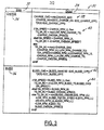
- Figure 3 is a table 30 that details the algorithm of the present invention for the CHARGE and BLEED states according to the preferred embodiment of the present invention, which has a linear transition region.
- the column 32 represents the state of the engine, CHARGE 34, or BLEED 36.
- the column 34 represents the output of the algorithm.
- the CHARGE_CMD is calculated 38.
- the algorithm determines 40 the applicable method for calculating the desired torque based on the relationship between the motor speed, SA_SPEED, and the lower limit of the commanded motor torque, CHARGE_RPM_LL.
- the desired torque is calculated as the maximum of either the value of the commanded motor torque for low motor speeds and idle speeds, or the desired torque calculated by -CHARGE_CMD/SA_SPEED. If the motor speed is greater than the lower limit of the commanded motor torque, then the desired torque is calculated as -CHARGE_CMD/SA_SPEED.
- the motor is in a transition state, and the formula for the transition region applies as discussed above with reference to equations (9) and (10). Note that when the motor speed is equal to the boundary limits for the Charge state the desired torque is equal to -CHARGE_CMD/SA_SPEED.
- the BLEED_CMD is calculated 42. Then the algorithm determines 44 the applicable method for calculating the desired torque based on the relationship between the motor speed, SA_SPEED, and the lower limit of the commanded motor torque, BLEED_RPM_LL. IF the motor speed is less than BLEED_RPM_LL, the desired torque is the minimum of either the value of the commanded motor torque for low motor speeds and idle speeds, or the desired torque calculated by BLEED_CMD/SA_SPEED.
- the desired torque is calculated as BLEED_CMD/SA_SPEED.
- the motor is in a transition state, and the formula for the transition region applies as discussed above with reference to equations (11) and (12).
- the linear representation for the transition region in the preferred embodiment is not the only possible representation. There are many alternatives that may be substituted. However, the upper and lower boundaries will always dictate the limits of the transition region.
- the commands generated in the vehicle system controller code must generally agree with the commands generated in an engine control unit. This maintains transparency to the driver during the CHARGE/BLEED modes.
- the calculated torque command is sent to the engine to either increase or decrease torque to compensate for the wheel torque and maintain the same overall torque, thereby maintaining transparency of the CHARGE/BLEED modes to the driver.
- an algorithm is provided as part of a code for a battery control system forming part of an overall Vehicle System Controller (VSC) that controls an electric motor and engine.
- VSC Vehicle System Controller
- the algorithm of the present invention generates torque commands to an engine and an electric motor that charges or is driven by a battery to maintain the battery at optimal SOC levels.
Applications Claiming Priority (2)
| Application Number | Priority Date | Filing Date | Title |
|---|---|---|---|
| US09/697,908 US6449537B1 (en) | 2000-10-27 | 2000-10-27 | Energy control strategy for a hybrid electric vehicle |
| US697908 | 2000-10-27 |
Publications (2)
| Publication Number | Publication Date |
|---|---|
| EP1234708A2 true EP1234708A2 (de) | 2002-08-28 |
| EP1234708A3 EP1234708A3 (de) | 2003-03-26 |
Family
ID=24803082
Family Applications (1)
| Application Number | Title | Priority Date | Filing Date |
|---|---|---|---|
| EP01000460A Withdrawn EP1234708A3 (de) | 2000-10-27 | 2001-09-13 | Hybridfahrzeug und dessen Steuerungseinrichtung |
Country Status (2)
| Country | Link |
|---|---|
| US (1) | US6449537B1 (de) |
| EP (1) | EP1234708A3 (de) |
Cited By (4)
| Publication number | Priority date | Publication date | Assignee | Title |
|---|---|---|---|---|
| WO2009100788A1 (de) * | 2008-02-15 | 2009-08-20 | Robert Bosch Gmbh | Verfahren und vorrichtung zum betreiben eines hybridantriebsystems |
| CN103569104A (zh) * | 2013-11-07 | 2014-02-12 | 阿尔特汽车技术股份有限公司 | 使用少缸发动机的hev动力转动系统的充电控制方法 |
| AT515645B1 (de) * | 2014-03-31 | 2016-05-15 | Wogro Gmbh | Vorrichtung zur Befestigung einer Armatur |
| CN110789361A (zh) * | 2018-08-01 | 2020-02-14 | 广州汽车集团股份有限公司 | 汽车电机扭矩限制方法、装置、整车控制器及系统 |
Families Citing this family (40)
| Publication number | Priority date | Publication date | Assignee | Title |
|---|---|---|---|---|
| US6622804B2 (en) * | 2001-01-19 | 2003-09-23 | Transportation Techniques, Llc. | Hybrid electric vehicle and method of selectively operating the hybrid electric vehicle |
| US6831429B2 (en) * | 2003-03-10 | 2004-12-14 | Visteon Global Technologies, Inc. | Prediction of available torque and power from battery-powered traction motor |
| US7614381B2 (en) * | 2003-03-28 | 2009-11-10 | Caterpillar Inc. | Power system with an integrated lubrication circuit |
| US6946818B2 (en) * | 2003-10-14 | 2005-09-20 | General Motors Corporation | Method of determining battery power limits for an energy storage system of a hybrid electric vehicle |
| US7110871B2 (en) * | 2003-10-14 | 2006-09-19 | General Motors Corporation | Method for determining preferred input operating points for a vehicle transmission |
| US7200476B2 (en) * | 2003-10-14 | 2007-04-03 | General Motors Corporation | Optimal selection of input torque considering battery utilization for a hybrid electric vehicle |
| US6957137B2 (en) | 2003-10-14 | 2005-10-18 | General Motors Corporation | Real-time operating parameter selection in a vehicular transmission |
| US7449891B2 (en) * | 2003-10-14 | 2008-11-11 | General Motors Corporation | Managing service life of a battery |
| US6868318B1 (en) | 2003-10-14 | 2005-03-15 | General Motors Corporation | Method for adjusting battery power limits in a hybrid electric vehicle to provide consistent launch characteristics |
| US7076356B2 (en) * | 2004-02-14 | 2006-07-11 | General Motors Corporation | Optimal selection of input torque with stability of power flow for a hybrid electric vehicle |
| US7295902B2 (en) * | 2004-04-30 | 2007-11-13 | General Motors Corporation | Torque management algorithm for hybrid electric vehicles |
| US7368886B2 (en) * | 2004-05-14 | 2008-05-06 | General Motors Corporation | Method of testing motor torque integrity in a hybrid electric vehicle |
| US7100362B2 (en) * | 2004-07-30 | 2006-09-05 | Ford Global Technologies, Llc | Vehicle and method for operating a vehicle to reduce exhaust emissions |
| US7308958B2 (en) * | 2004-11-01 | 2007-12-18 | Ford Global Technologies, Llc | Method for controlling a series hybrid electric vehicle |
| US7161316B2 (en) * | 2004-11-02 | 2007-01-09 | General Electric Company | Method and apparatus for discrete speed compensated torque step motor control |
| DE102005018437A1 (de) * | 2005-04-21 | 2006-10-26 | Robert Bosch Gmbh | Verfahren zum Betreiben eines Fahrzeug-Antriebs und Vorrichtung zur Durchführung des Verfahrens |
| US8384360B2 (en) * | 2005-04-27 | 2013-02-26 | Erik J. Cegnar | Hybrid battery |
| US11390165B2 (en) | 2005-11-17 | 2022-07-19 | Invently Automotive Inc. | Electric vehicle power management system |
| US11180025B2 (en) | 2005-11-17 | 2021-11-23 | Invently Automotive Inc. | Electric vehicle power management system |
| US11279233B2 (en) | 2005-11-17 | 2022-03-22 | Invently Automotive Inc. | Electric vehicle power management system |
| US11247564B2 (en) | 2005-11-17 | 2022-02-15 | Invently Automotive Inc. | Electric vehicle power management system |
| US11186173B2 (en) | 2005-11-17 | 2021-11-30 | Invently Automotive Inc. | Electric vehicle power management system |
| US11370302B2 (en) | 2005-11-17 | 2022-06-28 | Invently Automotive Inc. | Electric vehicle power management system |
| US11267338B2 (en) | 2005-11-17 | 2022-03-08 | Invently Automotive Inc. | Electric vehicle power management system |
| US11345236B2 (en) | 2005-11-17 | 2022-05-31 | Invently Automotive Inc. | Electric vehicle power management system |
| US11214144B2 (en) | 2005-11-17 | 2022-01-04 | Invently Automotive Inc. | Electric vehicle power management system |
| US11254211B2 (en) | 2005-11-17 | 2022-02-22 | Invently Automotive Inc. | Electric vehicle power management system |
| US11230190B2 (en) | 2005-11-17 | 2022-01-25 | Invently Automotive Inc. | Electric vehicle power management system |
| US10882399B2 (en) | 2005-11-17 | 2021-01-05 | Invently Automotive Inc. | Electric vehicle power management system |
| CN100999184A (zh) * | 2006-01-11 | 2007-07-18 | 北京嘉捷博大电动车有限公司 | 一种发动机液混联式后驱动混合动力车 |
| JP4341704B2 (ja) * | 2007-07-12 | 2009-10-07 | トヨタ自動車株式会社 | ハイブリッド車両およびハイブリッド車両の制御方法 |
| US8135532B2 (en) * | 2007-11-04 | 2012-03-13 | GM Global Technology Operations LLC | Method for controlling output power of an energy storage device in a powertrain system |
| US8295950B1 (en) | 2008-07-02 | 2012-10-23 | Jerry Lee Wordsworth | Intelligent power management system |
| US20130297125A1 (en) * | 2012-05-07 | 2013-11-07 | Ford Global Technologies, Llc | Torque filling and torque coordination during transients in a hybrid vehicle |
| KR101371475B1 (ko) * | 2012-10-31 | 2014-03-10 | 기아자동차주식회사 | 하이브리드 차량의 충전 제어 방법 및 시스템 |
| KR101509965B1 (ko) * | 2013-11-11 | 2015-04-07 | 현대자동차주식회사 | 배터리 충전 장치 및 방법 |
| CN106980725B (zh) * | 2017-03-28 | 2020-09-04 | 奇瑞汽车股份有限公司 | 一种汽车蓄电池选型的模拟仿真方法 |
| KR102515606B1 (ko) * | 2017-10-31 | 2023-03-28 | 삼성에스디아이 주식회사 | 배터리 충전량 표시 방법 및 이를 수행하는 배터리 팩 및 전자 기기 |
| CN112140901B (zh) * | 2019-06-28 | 2022-06-14 | 北京车和家信息技术有限公司 | 一种转矩控制方法和装置 |
| CN115465242B (zh) * | 2022-11-01 | 2023-03-24 | 临工重机股份有限公司 | 一种制动控制方法、装置以及电动宽体自卸车 |
Citations (5)
| Publication number | Priority date | Publication date | Assignee | Title |
|---|---|---|---|---|
| US5264764A (en) * | 1992-12-21 | 1993-11-23 | Ford Motor Company | Method for controlling the operation of a range extender for a hybrid electric vehicle |
| EP0645278A1 (de) * | 1993-09-24 | 1995-03-29 | Toyota Jidosha Kabushiki Kaisha | Generatorregler und Regelverfahren für ein Hybridfahrzeug |
| DE19945449A1 (de) * | 1998-09-22 | 2000-03-30 | Nissan Motor | Steuer- bzw. Regelvorrichtung für die Abgabeleistung eines Hybridfahrzeugs |
| US6109237A (en) * | 1997-02-04 | 2000-08-29 | Isad Electronic Systems Gmbh & Co. Kg | Apparatus for controlling the idling speed of an internal combustion engine |
| EP1075976A2 (de) * | 1999-08-10 | 2001-02-14 | Honda Giken Kogyo Kabushiki Kaisha | Verfahren und Vorrrichtung zum Regeln der Leistungserzeugung eines Hybridfahrzeugs |
Family Cites Families (9)
| Publication number | Priority date | Publication date | Assignee | Title |
|---|---|---|---|---|
| US4547678A (en) * | 1980-01-11 | 1985-10-15 | Califone International, Inc. | Hybrid electric vehicle control methods and devices |
| US5701965A (en) * | 1993-02-24 | 1997-12-30 | Deka Products Limited Partnership | Human transporter |
| US6054844A (en) * | 1998-04-21 | 2000-04-25 | The Regents Of The University Of California | Control method and apparatus for internal combustion engine electric hybrid vehicles |
| JP3099769B2 (ja) * | 1997-03-24 | 2000-10-16 | トヨタ自動車株式会社 | 動力出力装置およびその制御方法 |
| US5910722A (en) * | 1997-11-21 | 1999-06-08 | Lockheed Martin Corp. | Hybrid electric vehicle with reduced auxiliary power to batteries during regenerative braking |
| JP3412525B2 (ja) * | 1998-07-13 | 2003-06-03 | トヨタ自動車株式会社 | 動力出力装置及びその制御方法並びにハイブリッド車両 |
| US6209672B1 (en) * | 1998-09-14 | 2001-04-03 | Paice Corporation | Hybrid vehicle |
| JP3943726B2 (ja) * | 1998-09-16 | 2007-07-11 | 本田技研工業株式会社 | 回生制動装置 |
| US6196344B1 (en) * | 1999-09-10 | 2001-03-06 | Ford Global Technologies, Inc. | Control system and method for a hybrid electric vehicle |
-
2000
- 2000-10-27 US US09/697,908 patent/US6449537B1/en not_active Expired - Lifetime
-
2001
- 2001-09-13 EP EP01000460A patent/EP1234708A3/de not_active Withdrawn
Patent Citations (5)
| Publication number | Priority date | Publication date | Assignee | Title |
|---|---|---|---|---|
| US5264764A (en) * | 1992-12-21 | 1993-11-23 | Ford Motor Company | Method for controlling the operation of a range extender for a hybrid electric vehicle |
| EP0645278A1 (de) * | 1993-09-24 | 1995-03-29 | Toyota Jidosha Kabushiki Kaisha | Generatorregler und Regelverfahren für ein Hybridfahrzeug |
| US6109237A (en) * | 1997-02-04 | 2000-08-29 | Isad Electronic Systems Gmbh & Co. Kg | Apparatus for controlling the idling speed of an internal combustion engine |
| DE19945449A1 (de) * | 1998-09-22 | 2000-03-30 | Nissan Motor | Steuer- bzw. Regelvorrichtung für die Abgabeleistung eines Hybridfahrzeugs |
| EP1075976A2 (de) * | 1999-08-10 | 2001-02-14 | Honda Giken Kogyo Kabushiki Kaisha | Verfahren und Vorrrichtung zum Regeln der Leistungserzeugung eines Hybridfahrzeugs |
Cited By (5)
| Publication number | Priority date | Publication date | Assignee | Title |
|---|---|---|---|---|
| WO2009100788A1 (de) * | 2008-02-15 | 2009-08-20 | Robert Bosch Gmbh | Verfahren und vorrichtung zum betreiben eines hybridantriebsystems |
| CN103569104A (zh) * | 2013-11-07 | 2014-02-12 | 阿尔特汽车技术股份有限公司 | 使用少缸发动机的hev动力转动系统的充电控制方法 |
| CN103569104B (zh) * | 2013-11-07 | 2016-02-17 | 阿尔特汽车技术股份有限公司 | 使用少缸发动机的hev动力转动系统的充电控制方法 |
| AT515645B1 (de) * | 2014-03-31 | 2016-05-15 | Wogro Gmbh | Vorrichtung zur Befestigung einer Armatur |
| CN110789361A (zh) * | 2018-08-01 | 2020-02-14 | 广州汽车集团股份有限公司 | 汽车电机扭矩限制方法、装置、整车控制器及系统 |
Also Published As
| Publication number | Publication date |
|---|---|
| EP1234708A3 (de) | 2003-03-26 |
| US6449537B1 (en) | 2002-09-10 |
Similar Documents
| Publication | Publication Date | Title |
|---|---|---|
| EP1234708A2 (de) | Hybridfahrzeug und dessen Steuerungseinrichtung | |
| US6441574B1 (en) | Energy control strategy for a hybrid electric vehicle | |
| US7473206B2 (en) | Engine controller and control method | |
| US7034482B2 (en) | Regeneration control for hybrid vehicle | |
| EP1859985B1 (de) | Hybrides Fahrzeugsystem | |
| CA2380340C (en) | Control apparatus for electric motor and control apparatus for hybrid vehicle | |
| US7245094B2 (en) | Power output apparatus, motor vehicle equipped with power output apparatus, and control method of power output apparatus | |
| US5999864A (en) | Method of power management for a hybrid powertrain system | |
| US20110093151A1 (en) | Hybrid vehicle | |
| US20120016549A1 (en) | Control device and control method for electric motor vehicle | |
| US10486680B2 (en) | Hybrid vehicle | |
| CN111873983B (zh) | 一种混合动力汽车扭矩控制的方法、装置及混合动力汽车 | |
| JP2006275019A (ja) | ハイブリッド車の制御装置 | |
| JP2006246562A (ja) | ハイブリッド車およびその制御方法 | |
| JP2002058111A (ja) | ハイブリッド電気自動車用発電制御装置 | |
| EP3272603B1 (de) | Vorrichtung und verfahren zur steuerung von hybridfahrzeugen | |
| Hofman et al. | Rule-based energy management strategies for hybrid vehicle drivetrains: A fundamental approach in reducing computation time | |
| US6452352B1 (en) | Method of current interaction in an electric motor drive system having a load-dependent current generating system | |
| US7084589B1 (en) | Vehicle and method for controlling power to wheels in a vehicle | |
| US6795755B2 (en) | Method for operating a load-dependent power-generating system in a vehicle | |
| JPH1014010A (ja) | ハイブリッド車の発電制御装置 | |
| US11767039B2 (en) | Hybrid vehicle | |
| JP2007099022A (ja) | ハイブリッド車両の発電制御装置 | |
| JP7234875B2 (ja) | 車両の駆動制御装置 | |
| JP3894049B2 (ja) | ハイブリッド車両とその制御装置 |
Legal Events
| Date | Code | Title | Description |
|---|---|---|---|
| PUAI | Public reference made under article 153(3) epc to a published international application that has entered the european phase |
Free format text: ORIGINAL CODE: 0009012 |
|
| AK | Designated contracting states |
Kind code of ref document: A2 Designated state(s): AT BE CH CY DE DK ES FI FR GB GR IE IT LI LU MC NL PT SE TR |
|
| AX | Request for extension of the european patent |
Free format text: AL;LT;LV;MK;RO;SI |
|
| PUAL | Search report despatched |
Free format text: ORIGINAL CODE: 0009013 |
|
| AK | Designated contracting states |
Kind code of ref document: A3 Designated state(s): AT BE CH CY DE DK ES FI FR GB GR IE IT LI LU MC NL PT SE TR Designated state(s): AT BE CH CY DE DK ES FI FR GB GR IE IT LI LU MC NL PT SE TR |
|
| AX | Request for extension of the european patent |
Extension state: AL LT LV MK RO SI |
|
| RIC1 | Information provided on ipc code assigned before grant |
Ipc: 7B 60K 6/04 B Ipc: 7H 02J 7/14 B Ipc: 7B 60K 41/00 A |
|
| 17P | Request for examination filed |
Effective date: 20030828 |
|
| AKX | Designation fees paid |
Designated state(s): DE GB SE |
|
| 17Q | First examination report despatched |
Effective date: 20041223 |
|
| GRAP | Despatch of communication of intention to grant a patent |
Free format text: ORIGINAL CODE: EPIDOSNIGR1 |
|
| STAA | Information on the status of an ep patent application or granted ep patent |
Free format text: STATUS: THE APPLICATION IS DEEMED TO BE WITHDRAWN |
|
| 18D | Application deemed to be withdrawn |
Effective date: 20050726 |