EP1232990A2 - Einzelsteuerung für Sauggreifer in einem eine Vielzahl von Sauggreifern enthaltenden Ladegerät - Google Patents
Einzelsteuerung für Sauggreifer in einem eine Vielzahl von Sauggreifern enthaltenden Ladegerät Download PDFInfo
- Publication number
- EP1232990A2 EP1232990A2 EP02002127A EP02002127A EP1232990A2 EP 1232990 A2 EP1232990 A2 EP 1232990A2 EP 02002127 A EP02002127 A EP 02002127A EP 02002127 A EP02002127 A EP 02002127A EP 1232990 A2 EP1232990 A2 EP 1232990A2
- Authority
- EP
- European Patent Office
- Prior art keywords
- compressed air
- pressure
- line
- suction
- ejector
- Prior art date
- Legal status (The legal status is an assumption and is not a legal conclusion. Google has not performed a legal analysis and makes no representation as to the accuracy of the status listed.)
- Granted
Links
Images
Classifications
-
- B—PERFORMING OPERATIONS; TRANSPORTING
- B66—HOISTING; LIFTING; HAULING
- B66C—CRANES; LOAD-ENGAGING ELEMENTS OR DEVICES FOR CRANES, CAPSTANS, WINCHES, OR TACKLES
- B66C1/00—Load-engaging elements or devices attached to lifting or lowering gear of cranes or adapted for connection therewith for transmitting lifting forces to articles or groups of articles
- B66C1/02—Load-engaging elements or devices attached to lifting or lowering gear of cranes or adapted for connection therewith for transmitting lifting forces to articles or groups of articles by suction means
- B66C1/0256—Operating and control devices
-
- B—PERFORMING OPERATIONS; TRANSPORTING
- B65—CONVEYING; PACKING; STORING; HANDLING THIN OR FILAMENTARY MATERIAL
- B65G—TRANSPORT OR STORAGE DEVICES, e.g. CONVEYORS FOR LOADING OR TIPPING, SHOP CONVEYOR SYSTEMS OR PNEUMATIC TUBE CONVEYORS
- B65G47/00—Article or material-handling devices associated with conveyors; Methods employing such devices
- B65G47/74—Feeding, transfer, or discharging devices of particular kinds or types
- B65G47/90—Devices for picking-up and depositing articles or materials
- B65G47/91—Devices for picking-up and depositing articles or materials incorporating pneumatic, e.g. suction, grippers
- B65G47/918—Devices for picking-up and depositing articles or materials incorporating pneumatic, e.g. suction, grippers with at least two picking-up heads
Definitions
- the invention relates to a single control for suction pads in a variety of suction pads containing charger for transporting raw parts as well as for program-controlled Removal and transport of machined finished parts from the machined Blank.
- Chargers with a variety of suction pads are generally known. So from the DE 27 46 353 a vacuum load carrier for the transport of large-dimensional concrete slabs is known, where all vacuum cleaners are working at the same time. A targeted separation of finished parts from a machined blank is not possible.
- a device for holding printed circuit boards is known from DE 196 46 186 A1.
- a selection part tailored to the PCB in front of one with a plurality of suction plate provided on the surface distributed suction openings only the suction openings that are closed by the circuit board to be held become active become.
- This device can only be used for a special PCB series without retrofitting be used.
- a suction frame in which in addition to a conventional Suction cup frame further movable additional suction cups are arranged, which if they are not be lifted out of the suction pad. So that is a setting on the size of raw parts possible, but no problem-free removal of finished parts a machined blank.
- the aim and object of the invention is to provide a single control for suction pads in one Variety of suction cups containing charger can be found when using a single one Pressure line to each suction gripper in the functions suction, rest position and Blow off is controllable.
- the individual control for the suction pads in a charger consists of one for each Suction gripper leading pressure line, which is located on a near the suction gripper Ejector ends.
- the negative pressure in the ejector is emitted by the Compressed air generated via a nozzle in front of the ejector outlet. At this ejector exit is the suction pad connected.
- the compressed air outlet is through a controllable valve locked. If the compressed air outlet is open, compressed air flows through the nozzle and creates a negative pressure at the ejector outlet. The suction pad sucks. Is the compressed air outlet closed, the compressed air flows through the ejector outlet and releases the suction pad of the object attached to it.
- This valve can be different by compressed air Strength are actuated, which is fed to the ejector via the compressed air line.
- the pressure line can be connected to a compressed air line with a high pressure via a changeover valve Working pressure and switchable to a compressed air line with significantly lower blow-off pressure be connected, the blow-off pressure also by actuating a shut-off valve Rest position can be completely switched off for all unnecessary suction pads.
- the suction pads can be controlled separately, so that the finished parts are gripped in the machine according to the work program and be carried out. Only one pressure line to each suction pad is required, so the structure of the chargers is relatively simple. Suction cup malfunction are avoided by blowing in the suction cups that are not required.
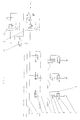
- a suction pad 1 is connected to an ejector outlet 2 with one in the immediate vicinity Ejector 3 connected.
- the ejector 3 is connected to a pressure line 4.
- the Ejector 3 is followed by a controllable valve 5, which is located in front of a compressed air outlet 6.
- the Valve 5 is followed by a silencer 7.
- a second path 8 is located on the pressure line 4 in front of the ejector 3 connected to control valve 5.
- the pressure line 4 is via a changeover valve 9 with a compressed air line 10 with a high working pressure and a compressed air line 11 with a lower one Blowdown pressure switchable connected.
- the compressed air in the compressed air line 10 is from a compressed air generator 12 supplied.
- a pressure reducer 13 is located on the compressed air line 10 connected, which is followed by the compressed air line 11 with blow-off pressure via a check valve 14.
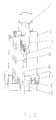
- the ejector 3 shows a compact ejector 3 with the secondary path 8 and the controllable valve 5.
- the ejector 3 is connected to the pressure line 4. Is in the ejector 3 a nozzle 15 in front of the ejector outlet 2. In front of the nozzle 15, the secondary path 8 branches off leads to controllable valve 5.
- the valve 5 consists of a slide 16, which is the compressed air outlet 6 closes, a spring 17 pressing against the slide 16 and one Piston 18.
- the changeover valves 9 are assigned to a work program Processing machine controlled. Depending on whether a finished part is removed or a remnant Should remain, the pressure line 4 to the compressed air line 10 or to the compressed air line 11 switched. Working pressure is supplied from the compressed air line 10. This work pressure opens the compressed air outlet 6 of the ejector 3 via the secondary path 8 by the slide 15 is moved against the spring 17. The compressed air with working pressure now flows through the nozzle 15 and generates 2 negative pressure in front of the ejector outlet. The suction pad 1 sucks.
- the ejector 3 is supplied with compressed air delivered significantly lower blow-off pressure. This pressure is not sufficient, the slide 16 to move against the spring 17.
- the compressed air outlet 6 remains closed. compressed air with blow-off pressure flows through the nozzle 15 and the ejector outlet 2 into the suction pad 1, which now detaches from the gripped part or cannot suck in any part.
- the check valve 14 is closed.
- the compressed air line 11 is now pressure free. All connected to the compressed air line 11 via the changeover valve 9 Suction pads 1 are now in the rest position.
Landscapes
- Engineering & Computer Science (AREA)
- Mechanical Engineering (AREA)
- Manipulator (AREA)
- Jet Pumps And Other Pumps (AREA)
Abstract
Description
- Fig. 1
- ein Schaltbild einer erfindungsgemäßen Einzelsteuerung für Sauggreifer
- Fig. 2
- einen Ejektor mit Zweitweg im Schnitt.
- 1
- Sauggreifer
- 2
- Ejektorausgang
- 3
- Ejektor
- 4
- Druckleitung
- 5
- Ventil
- 6
- Druckluftausgang
- 7
- Schalldämpfer
- 8
- Zweitweg
- 9
- Umschaltventil
- 10
- Druckluftleitung
- 11
- Druckluftleitung
- 12
- Drucklufterzeuger
- 13
- Druckminderer
- 14
- Sperrventil
- 15
- Düse
- 16
- Schieber
- 17
- Feder
- 18
- Kolben
Claims (5)
- Einzelsteuerung für Sauggreifer in einem eine Vielzahl von Sauggreifern enthaltenden Ladegerät, in dem zu jedem Sauggreifer (1) eine separate Druckleitung (4) führt, dadurch gekennzeichnet, dass eine einzige Druckleitung (4) zu einem von der Druckluft aktivierbaren Ejektor (3) führt, dessen Ejektorausgang (2) am Sauggreifer (1) angeschlossen und dessen Druckluftausgang (6) durch ein steuerbares Ventil (5) verschließbar ist, das über die Druckleitung (4) durch Druckluft verschiedener Stärke betätigbar ist.
- Einzelsteuerung für Sauggreifer nach Anspruch 1, dadurch gekennzeichnet, dass die Druckleitung (4) über ein Umschaltventil (9) an eine Druckluftleitung (10) mit hohem Arbeitsdruck und an eine Druckluftleitung (11) mit deutlich geringerem Abblasdruck umschaltbar angeschlossen, dass die Druckluftleitung (10) mit Arbeitsdruck direkt an einem Drucklufterzeuger (12) und dass die Druckluftleitung (11) mit Abblasdruck über ein Sperrventil (14) und einem Druckminderer (13) an dem Drucklufterzeuger (12) angeschlossen ist.
- Einzelsteuerung für Sauggreifer nach Anspruch 1, dadurch gekennzeichnet, dass die Druckleitung (4) über ein Dreiwegeventil an die Druckluftleitung (10) mit Arbeitsdruck und an die Druckluftleitung (11) mit Abblasdruck angeschlossen ist.
- Einzelsteuerung für Sauggreifer nach Anspruch 1, dadurch gekennzeichnet, dass der Ejektor (3) eine von der Druckluft durchströmte Düse (15) enthält, der die Ejektorausgangsöffnung folgt, dass sich vor der Düse (15) ein zu einem Schieber (16) führender Zweitweg (8) befindet und dass der Schieber, der mit einer Kraft vorgespannt ist, die einem unter dem Arbeitsdruck liegenden Druck entspricht, den Druckluftausgang (6) versperrt.
- Einzelsteuerung für Sauggreifer nach Anspruch 2, dadurch gekennzeichnet, dass die Umschaltventile (9) an den Druckluftleitungen (10, 11) dem Arbeitsprogramm der bedienten Arbeitsmaschine entsprechend gesteuert sind.
Applications Claiming Priority (2)
| Application Number | Priority Date | Filing Date | Title |
|---|---|---|---|
| DE10107001 | 2001-02-15 | ||
| DE2001107001 DE10107001C2 (de) | 2001-02-15 | 2001-02-15 | Steuerung für Sauggreifer in einem eine Vielzahl von Sauggreifern enthaltenden Ladegerät |
Publications (3)
| Publication Number | Publication Date |
|---|---|
| EP1232990A2 true EP1232990A2 (de) | 2002-08-21 |
| EP1232990A3 EP1232990A3 (de) | 2005-10-26 |
| EP1232990B1 EP1232990B1 (de) | 2006-11-02 |
Family
ID=7674114
Family Applications (1)
| Application Number | Title | Priority Date | Filing Date |
|---|---|---|---|
| EP20020002127 Expired - Lifetime EP1232990B1 (de) | 2001-02-15 | 2002-01-29 | Einzelsteuerung für Sauggreifer in einem eine Vielzahl von Sauggreifern enthaltenden Ladegerät |
Country Status (2)
| Country | Link |
|---|---|
| EP (1) | EP1232990B1 (de) |
| DE (1) | DE10107001C2 (de) |
Cited By (7)
| Publication number | Priority date | Publication date | Assignee | Title |
|---|---|---|---|---|
| WO2004024402A1 (en) * | 2002-09-11 | 2004-03-25 | Automazioni Industriali S.R.L. | Handling unit for cutting machines |
| WO2005087631A1 (de) * | 2004-03-11 | 2005-09-22 | Trumpf Sachsen Gmbh | Sauggreifereinstellsteuerung mit steuerventilblock |
| WO2006117093A1 (de) * | 2005-05-03 | 2006-11-09 | J. Schmalz Gmbh | Steuereinrichtung |
| EP1775243A2 (de) | 2005-10-12 | 2007-04-18 | Trumpf Maschinen Austria GmbH & CO. KG. | Greiferkopf mit Vakuumgreifern, Steuerventil und Verfahren zum Betrieb eines solchen Greiferkopfes |
| DE102007030362A1 (de) * | 2007-06-29 | 2009-01-02 | Hans-Jürgen Kasprich | Modulsystem zur Vakuumerzeugung |
| CN108780020A (zh) * | 2016-03-08 | 2018-11-09 | 阿瓦克瓦库特克尼克有限公司 | 压力测量 |
| US10399237B2 (en) * | 2016-06-10 | 2019-09-03 | Piab Aktiebolag | Controlling a vacuum system comprising a vacuum generator |
Families Citing this family (5)
| Publication number | Priority date | Publication date | Assignee | Title |
|---|---|---|---|---|
| DE10226002B4 (de) * | 2001-02-15 | 2007-10-18 | Trumpf Sachsen Gmbh | Druckluftsparanordnung für durch Ejektoren aktivierte Sauggreifer |
| DE102006010701B4 (de) * | 2005-03-17 | 2008-09-25 | Daimler Ag | Handhabungseinrichtung zum Transportieren flacher Werkstücke in einer Pressenanlage |
| DE102005021149B3 (de) * | 2005-05-03 | 2007-01-18 | J. Schmalz Gmbh | Steuereinrichtung |
| JP5938595B2 (ja) * | 2011-04-06 | 2016-06-22 | Smc株式会社 | エジェクタ付吸着装置 |
| DE102011107381A1 (de) * | 2011-06-29 | 2013-01-03 | Brötje-Automation GmbH | Handhabungswerkzeug |
Family Cites Families (5)
| Publication number | Priority date | Publication date | Assignee | Title |
|---|---|---|---|---|
| GB923724A (en) * | 1959-10-29 | 1963-04-18 | Peters G D & Co Ltd | Improvements in and relating to suction lifting equipment |
| DE1960106C3 (de) * | 1969-11-29 | 1975-01-23 | Hwm Hermann Weh Maschinenfabrik Kg, 4000 Duesseldorf | SelbstschlleBendes und -öffnendes Absperrventil für einander entgegengesetzte Strömungsrichtungen in Saugleitungen für Vakuumsaugteller |
| DE69225486T2 (de) * | 1991-09-09 | 1999-01-07 | Smc K.K., Tokio/Tokyo | Gerät zur funktionsüberwachung eines sauggreifers und verfahren zur einstellung des druckniveaus für die funktionsüberwachung eines saugreifers |
| JPH07157117A (ja) * | 1993-12-08 | 1995-06-20 | Fuji Photo Film Co Ltd | 板状体または箱体の真空チャック装置 |
| DE29902297U1 (de) * | 1999-02-09 | 2000-08-17 | Lösch Systembauteile GmbH, 67360 Lingenfeld | Saughaltevorrichtung |
-
2001
- 2001-02-15 DE DE2001107001 patent/DE10107001C2/de not_active Expired - Fee Related
-
2002
- 2002-01-29 EP EP20020002127 patent/EP1232990B1/de not_active Expired - Lifetime
Cited By (9)
| Publication number | Priority date | Publication date | Assignee | Title |
|---|---|---|---|---|
| WO2004024402A1 (en) * | 2002-09-11 | 2004-03-25 | Automazioni Industriali S.R.L. | Handling unit for cutting machines |
| WO2005087631A1 (de) * | 2004-03-11 | 2005-09-22 | Trumpf Sachsen Gmbh | Sauggreifereinstellsteuerung mit steuerventilblock |
| WO2006117093A1 (de) * | 2005-05-03 | 2006-11-09 | J. Schmalz Gmbh | Steuereinrichtung |
| EP1775243A2 (de) | 2005-10-12 | 2007-04-18 | Trumpf Maschinen Austria GmbH & CO. KG. | Greiferkopf mit Vakuumgreifern, Steuerventil und Verfahren zum Betrieb eines solchen Greiferkopfes |
| AT502563B1 (de) * | 2005-10-12 | 2007-06-15 | Trumpf Maschinen Austria Gmbh | Greiferkopf mit vakuumgreifer und steuerventil dazu sowie ein verfahren zum betrieb eines solchen |
| DE102007030362A1 (de) * | 2007-06-29 | 2009-01-02 | Hans-Jürgen Kasprich | Modulsystem zur Vakuumerzeugung |
| CN108780020A (zh) * | 2016-03-08 | 2018-11-09 | 阿瓦克瓦库特克尼克有限公司 | 压力测量 |
| EP3427030A4 (de) * | 2016-03-08 | 2019-11-27 | AVAC Vakuumteknik AB | Druckmessung |
| US10399237B2 (en) * | 2016-06-10 | 2019-09-03 | Piab Aktiebolag | Controlling a vacuum system comprising a vacuum generator |
Also Published As
| Publication number | Publication date |
|---|---|
| EP1232990B1 (de) | 2006-11-02 |
| EP1232990A3 (de) | 2005-10-26 |
| DE10107001A1 (de) | 2002-09-12 |
| DE10107001C2 (de) | 2003-04-17 |
Similar Documents
| Publication | Publication Date | Title |
|---|---|---|
| EP1232990A2 (de) | Einzelsteuerung für Sauggreifer in einem eine Vielzahl von Sauggreifern enthaltenden Ladegerät | |
| EP0371974B1 (de) | Hubsauger für eine transporteinrichtung | |
| DE112012006565T5 (de) | Verfahren und Vorrichtung zum Entfernen eines im Wesentlichen flachen Werkstücks von der Oberseite eines Stapels aus Werkstücken | |
| DE102021113345A1 (de) | Verfahren zum Betreiben einer Greifvorrichtung zur Vereinzelung von Wäschestücken aus einem Wäschehaufen | |
| DE102018214101B4 (de) | Vakuumerzeugervorrichtung | |
| EP1020388A2 (de) | Luftsteuer- und/oder Luftregelungseinrichtung | |
| DE102004038839B3 (de) | Greifereinheit, Bestückkopf und Verfahren zum Bestücken von Substraten mit elektrischen Bauelementen | |
| EP1393608B1 (de) | Bestückkopf mit einem schrittweise verdrehbaren rotor und einer pneumatischen drucksteuereinrichtung | |
| DE102021100214B4 (de) | Vorrichtung und Verfahren zur Handhabung von plattenförmigen Teilen | |
| EP1725484B1 (de) | Sauggreifereinstellsteuerung mit steuerventilblock | |
| DE10308680A1 (de) | Anlage zur Entsorgung von taktweise anfallenden Werkstücken | |
| DE3105977C2 (de) | Vorrichtung zum Steuern der Drehbewegung bei einem zahnärztlichen Handstück | |
| DE102008016597B4 (de) | Bogenanleger mit einem Bogentrenner | |
| DE10151635B4 (de) | Unterdruckhaltevorrichtung | |
| EP1719720B1 (de) | Steuereinrichtung für einen Sauggreifer | |
| DE3902663A1 (de) | Hubsauger fuer eine transporteinrichtung | |
| DE102007001722A1 (de) | Transportvorrichtung, Zuführungsvorrichtung, Entnahmevorrichtung und Vorrichtung zum Aufnehmen, Transportieren und Sortieren von elektronischen Bauelementen | |
| EP2797398B1 (de) | Bestückkopf zum Bestücken von Substraten mit elektrischen Bauelementen mittels einer pneumatischen Einrichtung | |
| DE10118386B4 (de) | Ladevorrichtung mit gezielter Sauggreifersteuerung | |
| EP1734804B1 (de) | Vorrichtung zum Handhaben von Bauteilen und zugehöriges Steuerverfahren | |
| EP1877331B1 (de) | Steuereinrichtung | |
| DE202021003811U1 (de) | Greifereinheit | |
| DE19821389B4 (de) | Verfahren und Vorrichtung zum Handling von Werkstücken | |
| EP3636397B1 (de) | Verfahren zum betrieb eines transfersystems und transfersystem | |
| DE19720972C1 (de) | Bogenanleger |
Legal Events
| Date | Code | Title | Description |
|---|---|---|---|
| PUAI | Public reference made under article 153(3) epc to a published international application that has entered the european phase |
Free format text: ORIGINAL CODE: 0009012 |
|
| AK | Designated contracting states |
Kind code of ref document: A2 Designated state(s): AT BE CH CY DE DK ES FI FR GB GR IE IT LI LU MC NL PT SE TR |
|
| AX | Request for extension of the european patent |
Free format text: AL;LT;LV;MK;RO;SI |
|
| PUAL | Search report despatched |
Free format text: ORIGINAL CODE: 0009013 |
|
| AK | Designated contracting states |
Kind code of ref document: A3 Designated state(s): AT BE CH CY DE DK ES FI FR GB GR IE IT LI LU MC NL PT SE TR |
|
| AX | Request for extension of the european patent |
Extension state: AL LT LV MK RO SI |
|
| 17P | Request for examination filed |
Effective date: 20051028 |
|
| GRAP | Despatch of communication of intention to grant a patent |
Free format text: ORIGINAL CODE: EPIDOSNIGR1 |
|
| AKX | Designation fees paid |
Designated state(s): CH FI FR IT LI |
|
| REG | Reference to a national code |
Ref country code: DE Ref legal event code: 8566 |
|
| GRAS | Grant fee paid |
Free format text: ORIGINAL CODE: EPIDOSNIGR3 |
|
| GRAA | (expected) grant |
Free format text: ORIGINAL CODE: 0009210 |
|
| AK | Designated contracting states |
Kind code of ref document: B1 Designated state(s): CH FI FR IT LI |
|
| REG | Reference to a national code |
Ref country code: CH Ref legal event code: EP |
|
| ET | Fr: translation filed | ||
| PLBE | No opposition filed within time limit |
Free format text: ORIGINAL CODE: 0009261 |
|
| STAA | Information on the status of an ep patent application or granted ep patent |
Free format text: STATUS: NO OPPOSITION FILED WITHIN TIME LIMIT |
|
| 26N | No opposition filed |
Effective date: 20070803 |
|
| PGFP | Annual fee paid to national office [announced via postgrant information from national office to epo] |
Ref country code: FI Payment date: 20140122 Year of fee payment: 13 Ref country code: CH Payment date: 20140124 Year of fee payment: 13 |
|
| PGFP | Annual fee paid to national office [announced via postgrant information from national office to epo] |
Ref country code: IT Payment date: 20140128 Year of fee payment: 13 Ref country code: FR Payment date: 20140124 Year of fee payment: 13 |
|
| REG | Reference to a national code |
Ref country code: CH Ref legal event code: PL |
|
| PG25 | Lapsed in a contracting state [announced via postgrant information from national office to epo] |
Ref country code: FI Free format text: LAPSE BECAUSE OF NON-PAYMENT OF DUE FEES Effective date: 20150129 Ref country code: LI Free format text: LAPSE BECAUSE OF NON-PAYMENT OF DUE FEES Effective date: 20150131 Ref country code: CH Free format text: LAPSE BECAUSE OF NON-PAYMENT OF DUE FEES Effective date: 20150131 |
|
| REG | Reference to a national code |
Ref country code: FR Ref legal event code: ST Effective date: 20150930 |
|
| PG25 | Lapsed in a contracting state [announced via postgrant information from national office to epo] |
Ref country code: FR Free format text: LAPSE BECAUSE OF NON-PAYMENT OF DUE FEES Effective date: 20150202 |
|
| PG25 | Lapsed in a contracting state [announced via postgrant information from national office to epo] |
Ref country code: IT Free format text: LAPSE BECAUSE OF NON-PAYMENT OF DUE FEES Effective date: 20150129 |