EP3636397B1 - Verfahren zum betrieb eines transfersystems und transfersystem - Google Patents
Verfahren zum betrieb eines transfersystems und transfersystem Download PDFInfo
- Publication number
- EP3636397B1 EP3636397B1 EP19195483.3A EP19195483A EP3636397B1 EP 3636397 B1 EP3636397 B1 EP 3636397B1 EP 19195483 A EP19195483 A EP 19195483A EP 3636397 B1 EP3636397 B1 EP 3636397B1
- Authority
- EP
- European Patent Office
- Prior art keywords
- tooling
- transfer system
- supplying
- compressed air
- energy coupling
- Prior art date
- Legal status (The legal status is an assumption and is not a legal conclusion. Google has not performed a legal analysis and makes no representation as to the accuracy of the status listed.)
- Active
Links
Images


Classifications
-
- B—PERFORMING OPERATIONS; TRANSPORTING
- B25—HAND TOOLS; PORTABLE POWER-DRIVEN TOOLS; MANIPULATORS
- B25J—MANIPULATORS; CHAMBERS PROVIDED WITH MANIPULATION DEVICES
- B25J15/00—Gripping heads and other end effectors
- B25J15/0052—Gripping heads and other end effectors multiple gripper units or multiple end effectors
- B25J15/0061—Gripping heads and other end effectors multiple gripper units or multiple end effectors mounted on a modular gripping structure
-
- B—PERFORMING OPERATIONS; TRANSPORTING
- B25—HAND TOOLS; PORTABLE POWER-DRIVEN TOOLS; MANIPULATORS
- B25J—MANIPULATORS; CHAMBERS PROVIDED WITH MANIPULATION DEVICES
- B25J15/00—Gripping heads and other end effectors
- B25J15/06—Gripping heads and other end effectors with vacuum or magnetic holding means
- B25J15/0616—Gripping heads and other end effectors with vacuum or magnetic holding means with vacuum
- B25J15/0625—Gripping heads and other end effectors with vacuum or magnetic holding means with vacuum provided with a valve
-
- B—PERFORMING OPERATIONS; TRANSPORTING
- B25—HAND TOOLS; PORTABLE POWER-DRIVEN TOOLS; MANIPULATORS
- B25J—MANIPULATORS; CHAMBERS PROVIDED WITH MANIPULATION DEVICES
- B25J15/00—Gripping heads and other end effectors
- B25J15/06—Gripping heads and other end effectors with vacuum or magnetic holding means
- B25J15/0616—Gripping heads and other end effectors with vacuum or magnetic holding means with vacuum
- B25J15/065—Gripping heads and other end effectors with vacuum or magnetic holding means with vacuum provided with separating means for releasing the gripped object after suction
- B25J15/0658—Pneumatic type, e.g. air blast or overpressure
-
- B—PERFORMING OPERATIONS; TRANSPORTING
- B25—HAND TOOLS; PORTABLE POWER-DRIVEN TOOLS; MANIPULATORS
- B25J—MANIPULATORS; CHAMBERS PROVIDED WITH MANIPULATION DEVICES
- B25J19/00—Accessories fitted to manipulators, e.g. for monitoring, for viewing; Safety devices combined with or specially adapted for use in connection with manipulators
- B25J19/0025—Means for supplying energy to the end effector
Definitions
- the invention relates to a method for operating a transfer system according to claim 1 and a transfer system for carrying out this method according to claim 4.
- a pneumatic handling device which comprises a manipulator with a crossbeam, which comprises at least one adapter mounted on the crossbeam and which comprises at least one compressed air supply, each adapter comprising a base frame and at least one tooling with a tooling tube, each base frame comprising at least one energy coupling for the at least one tooling tube and wherein each energy coupling for connecting the at least one tooling comprises at least two outlets for compressed air and/or vacuum.
- a handling device which comprises at least one vacuum gripper for sucking up a workpiece, with at least one vacuum generator that can be operated by means of a compressed air supply for supplying the vacuum gripper with vacuum, and with at least one controllable control valve, by means of which the compressed air supply to the vacuum generator can be controlled, with the control valve being assigned a control device for activating the control valve as required, the handling device having an evaluation unit for evaluating operating data of the vacuum generator and/or operating data of the handling device and for generating control signals as a function of the evaluated operating data, the evaluating unit on the handling device is arranged and wherein the Control device controls the control valve depending on the control signals transmitted by the evaluation unit.
- a robot arm coupling for connecting a tool to a robot arm having a mounting interface for mounting the robot arm coupling to a robot arm, a coupler interface to which differently actuated tools can be detachably and interchangeably coupled, a fluid inlet port, a plurality of interface fluid ports, at least one valve in fluid communication with the fluid inlet port and adjustable to at least first and second operating conditions; a suction device that applies fluid suction pressure to an interface fluid port, wherein when a first or a second or a third tool is mounted on the coupling interface, either one of them can be controlled by the same at least one valve.
- the object of the invention is to propose a method for operating a transfer device and a transfer device in which, with a constant interface between the tooling tube and the base frame, it is possible to freely choose between different operating modes of vacuum generation.
- the method according to the invention for operating a transfer system provides that the transfer system operates either according to a first operating mode, which is also referred to as central vacuum generation is operated or is operated according to a second operating mode, which is also referred to as decentralized vacuum generation, wherein in the first operating mode (central vacuum) a control means is switched to a first switching position, so that a first supply means is used to supply a number of tooling tubes is activated, so that the tooling tubes are made available to the tooling tubes from the first supply means via a supply line in each case to one energy coupling per tooling tube, either compressed air or vacuum, with the control means being switched to a second switching position in the second operating mode (decentralized vacuum), so that to supply the number of tooling tubes, a second supply means is activated, so that the tooling tubes from the second supply means via the respective energy coupling via a first supply line compressed air for blowing and each via a second supply line compressed air for vacuum generation tion is made available.
- a first operating mode central vacuum
- the invention further provides that for operation of the transfer system in accordance with the first operating mode, the tooling pipes are supplied by the second supply means (decentralized) and that for operation of the transfer system in accordance with the second operating mode, the tooling pipes are supplied by the first supply means through check valves, which are arranged between the first, central supply means and the second, decentralized supply means is shut off.
- the method provides that for operation of the transfer system according to the first operating mode (central) only a first output of the respective energy coupling for an alternate supply of compressed air or vacuum is used for each tooling tube and a respective existing second output through a closure, in particular a valve or a plug, is closed and that for operation of the transfer system according to the second operating mode (decentralized) for each tooling pipe the first output of the respective energy coupling is used to supply compressed air for blowing off and the second output of the respective energy coupling is used to supply compressed air Compressed air is used to generate a vacuum.
- This makes it possible to pneumatically supply tooling tubes via only two outputs of the energy coupling both in the central operating mode and in the decentralized operating mode.
- a transfer system for carrying out a method according to one of claims 1 to 3 is designed such that the transfer system comprises a first supply means connected to the compressed air supply for providing compressed air and vacuum, that the transfer system comprises a second supply means connected to the compressed air supply for providing compressed air and that the transfer system comprises a control means, wherein in a first switch position of the control means the at least one tooling tube is supplied with compressed air and vacuum via the first supply means and wherein in a second switch position of the control means the at least one tooling tube is supplied with compressed air via the second supply means.
- the tooling tubes installed on the transfer device can be supplied with compressed air or vacuum centrally or decentrally, depending on the requirements, without the need for further replacement or conversion of components.
- this transfer system provides that the first supply means (central) comprises at least one vacuum generating device operated with compressed air and that the second supply means (decentral) comprises a first valve and a second valve, the first supply means being connected to a first input of the energy coupling of the is connected to the base frame and feeds it either with compressed air or vacuum and the second supply means is connected to the first input and a second input of the energy coupling of the base frame and feeds one of the inputs with compressed air and the other of the inputs also with compressed air.
- the energy coupling only has to provide two inputs for both supply variants.
- control means and the second supply means are arranged (decentrally) on the manipulator or on the crossbeam or on the base frame and for the first supply means to be arranged (centrally) on the base frame or the crossbeam. This keeps the weight of the base frame low.
- control means comprises a switching valve and a plurality of check valves, the check valves between the first supply means and between the second supply means and the at least one energy coupling are arranged in such a way that in the first switching position of the control means, supply lines between the second supply means and the inputs of the energy coupling are blocked and the supply line or supply lines between the first supply means and the input or inputs of the Energy coupling is or are open and that in the second switching position of the control means the supply line or lines between the first supply means and the input or inputs of the energy coupling is or are blocked and the supply lines between the second supply means and the inputs of the energy coupling are open.
- one of the tooling tubes is connected to one of the energy couplings in such a way that the tooling tube and the suction grippers arranged on it are connected to one of the outputs of the energy coupling in the first switching position of the control means, which is connected to that input of the energy coupling , which is connected to the first supply means, with the respective other output of the energy coupling being closed in particular by the tooling pipe, or that one of the tooling pipes is connected to one of the energy couplings in such a way that the tooling pipe and the suction pads arranged on it are in the second switching position of the control means are connected to the outputs of the energy coupling, which are connected to the inputs of the energy coupling, which are connected to the second supply means.
- This can do that respective tooling tube can be prepared in the simplest way for a centralized or decentralized supply.
- the transfer system comprises two base frames connected to the crossbeam, each with two energy couplings, and that the transfer system comprises four tooling tubes, which are connected to the four energy couplings.
- Such a transfer system is particularly suitable for handling two flat workpieces.
- the at least one vacuum generating device of the first supply means is designed as a pneumatically controlled vacuum generating device with a compact ejector or that the at least one vacuum generating device of the first supply means is designed as an electrically controlled vacuum generating device with a compact ejector.
- the first supply means can be optimally designed for the control technology preferred at the transfer device.
- each tooling which is operated in the second switching position of the control means, comprises an individual ejector for vacuum generation on each of its suction pads.
- the tooling can generate different suction forces on its individual suction pads that are adapted to the function of the individual suction pads by using different individual ejectors.
- a central vacuum generation means a vacuum generation that is close to a tooling and in particular to a crossbeam and/or to a base frame.
- decentralized vacuum generation is understood to mean vacuum generation that takes place directly on each suction gripper of the tooling.
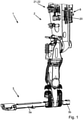
- FIG. 1 shows the figure 1 a perspective view of a manipulator 2 with a crossbar 3 fixed to the manipulator 2, which is also referred to as a crossbar.
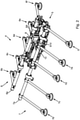
- the figure 2 shows an adapter 4 in a perspective view, which includes a base frame 5 and two toolings 6, 7 connected to the base frame 5 via receptacles.
- the toolings 6, 7 include tooling tubes 6a, 7a and suction grippers 6b to 6f and 7b to 7f connected to the tooling tubes 6a, 7a.
- the base frame 5 is also referred to as a support frame.
- the transfer system 1 includes in the figures 1 and 2 shown components, wherein the adapter 4 is connected in the assembled state to a left arm 3a of the crossbeam 3 and it is provided to connect a further adapter, not shown, to a right arm 3b of the crossbeam 3, which is only partially shown.
- the transfer system 1 includes the manipulator 2 with its crossbar 3, the adapter 4 mounted on the crossbar 3 and a compressed air supply 8.
- the base frame 5 includes a first energy coupling 9 for connecting the first tooling 6 and a second energy coupling 10 for connecting the second tooling 7 (see figure 2 ).
- the transfer system 1 comprises a first supply means 19 connected to the compressed air supply 8 for providing compressed air and vacuum.
- the first supply means 19 is arranged on the base frame 5 or, according to embodiment variants that are not shown, on the crossbeam 3 or on the manipulator 2 .
- the transfer system 1 includes a second supply means 20 connected to the compressed air supply 8 for providing compressed air and vacuum.
- the supply means 20 is arranged on the manipulator 2 (see FIG figure 1 ).
- the transfer system 1 includes a control means 21, which is designed as a switching valve 22 (see figure 1 ).
- first switching position S1 (see figure 5 or 7) of the control means 21, the two tooling tubes 6a, 7a are supplied with compressed air and vacuum via the first supply means 19.
- second switching position S2 (see figure 6 or 8) of the control means 21, the two tooling tubes 6a, 7a are supplied with compressed air and vacuum via the second supply means 20.
- the tooling 6 includes a plug S9, with which it is connected to the first energy coupling 9 of the base frame 5 (see also figure 2 ).
- the tooling 7 also includes a plug S10, with which it is connected to the second energy coupling 10 of the base frame 5 (see also figure 2 ). If operation takes place in the second switching position S2, tooling is installed which includes individual ejectors for vacuum generation, with each suction gripper having a Single ejector is assigned.
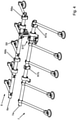
- each tooling 6, 7 includes two tabs R6a, R6b or R7a, R7b, which are inserted into associated receptacles A6a, A6b or A7a, A7b of the base frame 5 to connect the tooling 6, 7 to the base frame 5 (cf Figures 3 and 4 ).
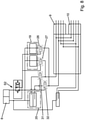
- the first supply means 19 comprises two vacuum generating devices 23, 24.
- the vacuum generating device 23 is connected to the second input 16 of the second energy coupling 10 via a supply line 23a and the vacuum generating device 24 is connected to the first input 11 of the first energy coupling 9 via a supply line 24a.
- compressed air or vacuum is available at the outlets 13 and 18 in each case.
- the vacuum generating devices 23, 24 are designed as pneumatically controlled compact ejectors, which are sold, for example, by J. Schmalz GmbH under the product name SCPi.
- the pneumatic plan also shows that the second supply means 20 includes a first valve 25-1.
- the first valve 25-1 is connected via a supply line 25a to the first input 11 of the first energy clutch 9 and to the first input 15 of the second energy clutch 10 and can make compressed air available via this supply line 25a.
- the second supply means 20 includes a second valve 25-2. This is via a further supply line 25b connected to the second input 12 of the first energy coupling 9 and to the second input 16 of the second energy coupling 10 and can provide compressed air via this supply line 25b.
- the pneumatic plan also shows that switching between the in the figure 5 shown first switching position S1 and in the figure 6 shown second switching position S2 by means of seven check valves 26 to 32 takes place.
- the five check valves 26 to 30 are assigned to the first supply means 19 and the two check valves 31 , 32 are assigned to the second supply means 20 .
- Compressed air is applied to the five shut-off valves 26 to 30 via the changeover valve 22 located in the switching position S1, and they are thereby opened.
- the supply lines 23a and 24a which lead from the first supply means 19 to the energy couplings 9 or 10, are open, so that the energy couplings 9, 10 can be optionally supplied with vacuum or compressed air.
- the check valves 28, 29 are also open, so that the first supply means 19 can be supplied with compressed air from the compressed air supply 8.
- the check valve 30 is also open, so that the first supply means 19 can be supplied with compressed air for control purposes.
- the check valves 31, 32 which are assigned to the second supply means 20, are not acted upon by compressed air in the switching position S1 and are therefore blocked, so that there is no connection between the second supply means 20 and the energy couplings 9, 10.
- the first supply means 19 is arranged on the base frame 5 . According to an embodiment variant that is not shown, provision is also made for arranging this on the crossbeam or on the manipulator.
- the toolings 6, 7 are supplied centrally.
- the exit 14 of Energy coupling 9 and the output 17 of the energy coupling 10 are each closed by a schematically illustrated closure V14 or V17 when the toolings 6, 7 are operated centrally.
- the closures V14, V17 can each be formed by a plug.
- each energy coupling 9, 10 comprises two further inputs to which pre-air and return air are connected. Such an additional supply is optionally provided.
- the in the figures 7 and 8th shown pneumatic diagrams are analogous to those in the figures 5 and 6 shown pneumatic plans executed.
- the first supply means 19 is not equipped with vacuum generating devices, which are designed as pneumatically controlled compact ejectors, but with vacuum generating devices, which are designed as electrically controlled compact ejectors.
- Electrically controlled compact ejectors are sold, for example, by J. Schmalz GmbH under the product name SXMP.
- SXMP product name
- the use of electrically controlled compact ejectors simplifies the pneumatic plan in that only two check valves 26, 27 have to be assigned to the first supply means 19. Accordingly, in switch position S1 (see figure 7 ) the check valves 26, 27 are opened and the check valves 31, 32, which are assigned to the second supply means 20, are closed.
- the transfer system 1 is shown schematically.
- the crossbeam 3 of the manipulator 2 carries the base frame 5 and a further base frame 105.
- the two toolings 6, 7 are arranged on the base frame 5 and two further toolings 106, 107 are arranged on the second base frame 105.
- the transfer device 1 for the toolings 6, 7 comprises the two vacuum generating devices 23, 24 and for the tooling 106, 107 two further vacuum generating devices 123, 124.
Landscapes
- Engineering & Computer Science (AREA)
- Robotics (AREA)
- Mechanical Engineering (AREA)
- Jet Pumps And Other Pumps (AREA)
Description
- Die Erfindung betrifft ein Verfahren zum Betrieb eines Transfersystems nach Anspruch 1 sowie ein Transfersystem zur Durchführung dieses Verfahrens nach Anspruch 4.
- Aus der
DE 20 2016 102 137 U1 ist eine pneumatische Handhabungsvorrichtung bekannt, welche einen Manipulator mit einer Quertraverse umfasst, welche wenigstens einen an der Quertraverse montierten Adapter umfasst und welche mindestens eine Druckluftversorgung umfasst, wobei jeder Adapter ein Grundgestell und wenigstens ein Tooling mit einem Toolingrohr umfasst, wobei jedes Grundgestell mindestens eine Energiekupplung für das mindestens eine Toolingrohr umfasst und wobei jede Energiekupplung zum Anschluss des wenigstens einen Toolings mindestens zwei Ausgänge für Druckluft und/oder Vakuum umfasst. - Aus der
EP 2 960 024 A2 1 ist ein Anlage zur Handhabung von Werkstücken, mit einer Handhabungsvorrichtung, welche wenigstens einen Unterdruckgreifer zum Ansaugen eines Werkstückes umfasst, mit wenigstens einen mittels Druckluftzufuhr betreibbaren Unterdruckerzeuger zur Versorgung des Unterdruckgreifers mit Unterdruck und mit wenigstens einem ansteuerbaren Steuerventil, mittels welchem die Druckluftzufuhr zu dem Unterdruckerzeuger steuerbar ist, wobei dem Steuerventil eine Steuereinrichtung zur bedarfsgerechten Ansteuerung des Steuerventils zugeordnet ist, wobei die Handhabungsvorrichtung eine Auswerteeinheit zur Auswertung von Betriebsdaten des Unterdruckerzeugers und/oder von Betriebsdaten der Handhabungsvorrichtung sowie zur Erzeugung von Steuersignalen in Abhängigkeit der ausgewerteten Betriebsdaten aufweist, wobei die Auswerteeinheit an der Handhabungsvorrichtung angeordnet ist und wobei die Steuereinrichtung das Steuerventil in Abhängigkeit der von der Auswerteeinheit übermittelten Steuersignale ansteuert. - Aus der nachveröffentlichten
EP 3 694 692 A1 ist eine Roboterarmkupplung zum Verbinden eines Werkzeugs mit einem Roboterarm bekannt, wobei die Roboterarmkupplung eine Montageschnittstelle zum Montieren der Roboterarmkupplung an einem Roboterarm, eine Kopplerschnittstelle, an der unterschiedlich betätigte Werkzeuge lösbar und austauschbar gekoppelt werden können, eine Flüssigkeitseinlassöffnung, eine Vielzahl von Grenzflächenfluidanschlüssen, mindestens ein Ventil in Fluidverbindung mit der Fluideinlassöffnung und einstellbar auf mindestens einen ersten und einen zweiten Betriebszustand; eine Saugvorrichtung, die einen Fluidsaugdruck auf einen Grenzflächenfluidanschluss ausübt, umfasst, wobei wenn ein erstes oder ein zweites oder ein drittes Werkzeug an der Kupplungsschnittstelle montiert ist, eines von beiden durch dasselbe mindestens eine Ventil gesteuert werden kann. - Es ist Aufgabe der Erfindung ein Verfahren zum Betrieb einer Transfereinrichtung sowie eine Transfereinrichtung vorzuschlagen, bei welchem bzw. bei welcher bei einer gleichbleibenden Schnittstelle zwischen Toolingrohr und Grundgestell zwischen verschiedenen Betriebsarten der Vakuumerzeugung frei gewählt werden kann.
- Diese Aufgabe wird durch den Anspruch 1 bzw. 4 gelöst. In den jeweiligen Unteransprüchen sind vorteilhafte und zweckmäßige Weiterbildungen angegeben.
- Das erfindungsgemäße Verfahren zum Betrieb eines Transfersystems sieht vor, dass das Transfersystem entweder nach einer ersten Betriebsart, welche auch als zentrale Vakuumerzeugung bezeichnet wird, betrieben wird oder nach einer zweiten Betriebsart, welche auch als dezentrales Vakuumerzeugung bezeichnet wird, betrieben wird, wobei in der ersten Betriebsart (zentrales Vakuum) ein Steuermittel in eine erste Schaltstellung geschaltet wird, so dass zur Versorgung einer Zahl von Toolingrohren ein erstes Versorgungsmittel aktiviert wird, so dass den Toolingrohren von dem ersten Versorgungsmittel über jeweils eine Versorgungsleitung an jeweils einer Energiekupplung pro Toolingrohr wahlweise Druckluft oder Vakuum zur Verfügung gestellt wird, wobei in der zweiten Betriebsart (dezentrales Vakuum) das Steuermittel in eine zweite Schaltstellung geschaltet wird, so dass zur Versorgung der Zahl von Toolingrohren ein zweites Versorgungsmittel aktiviert wird, so dass den Toolingrohren von dem zweiten Versorgungsmittel über die jeweilige Energiekupplung jeweils über eine erste Versorgungsleitung Druckluft zum Abblasen und jeweils über eine zweite Versorgungsleitung Druckluft zur Vakuumerzeugung zur Verfügung gestellt wird. Hierdurch können die an der Transfereinrichtung verbauten Toolingrohre abhängig von den Erfordernissen zentral oder dezentral mit Druckluft bzw. Vakuum versorgt werden, ohne dass ein weiterer Austausch oder Umbau von Komponenten erforderlich ist.
- Die Erfindung sieht weiterhin vor, dass für einen Betrieb des Transfersystems entsprechend der ersten Betriebsart eine Versorgung der Toolingrohre durch das zweite Versorgungsmittel (dezentral) und dass für einen Betrieb des Transfersystems entsprechend der zweiten Betriebsart eine Versorgung der Toolingrohre durch das erste Versorgungsmittel durch Sperrventile, welche zwischen dem ersten, zentralen Versorgungsmittel und dem zweiten, dezentralen Versorgungsmittel angeordnet sind, abgesperrt wird. Hierdurch wird eine ungewünschte, gegenseitige Beeinflussung der in den jeweiligen Betriebsarten aktiven bzw. passiven Versorgungseinrichtungen unterbunden, so dass Funktionssicherheit und ein sparsamer Umgang mit Druckluft sichergestellt ist.
- Schließlich sieht das Verfahren vor, dass für einen Betrieb des Transfersystems nach der ersten Betriebsart (zentral) je Toolingrohr nur ein erster Ausgang der jeweiligen Energiekupplung für eine wechselweise Zuleitung von Druckluft oder von Vakuum genutzt wird und ein jeweils vorhandener zweiter Ausgang durch einen Verschluss, insbesondere ein Ventil oder einen Stopfen, verschlossen wird und dass für einen Betrieb des Transfersystems nach der zweiten Betriebsart (dezentral) je Toolingrohr der erste Ausgang der jeweiligen Energiekupplung für eine Zuleitung von Druckluft zum Abblasen genutzt wird und der zweite Ausgang der jeweiligen Energiekupplung für eine Zuleitung von Druckluft zur Vakuumerzeugung genutzt wird. Hierdurch ist es möglich, Toolingrohre über nur zwei Ausgänge der Energiekupplung sowohl in der zentralen Betriebsart als auch in der dezentralen Betriebsart pneumatisch zu versorgen.
- Ein Transfersystem zur Durchführung eines Verfahrens nach einem der Ansprüche 1 bis 3 ist derart ausgebildet, dass das Transfersystem ein erstes an die Druckluftversorgung angeschlossenes Versorgungsmittel zur Bereitstellung von Druckluft und Vakuum umfasst, dass das Transfersystem ein zweites an die Druckluftversorgung angeschlossenes Versorgungsmittel zur Bereitstellung von Druckluft umfasst und dass das Transfersystem ein Steuermittel umfasst, wobei in einer ersten Schaltstellung des Steuermittels das wenigstens eine Toolingrohr über das erste Versorgungsmittel mit Druckluft und Vakuum versorgt ist und wobei in einer zweiten Schaltstellung des Steuermittels das wenigstens eine Toolingrohr über das zweite Versorgungsmittel mit Druckluft versorgt ist. Hierdurch können die an der Transfereinrichtung verbauten Toolingrohre abhängig von den Erfordernissen zentral oder dezentral mit Druckluft bzw. Vakuum versorgt werden, ohne dass ein weiterer Austausch oder Umbau von Komponenten erforderlich ist.
- Erfindungsgemäß ist es bei diesem Transfersystem vorgesehen, dass das erste Versorgungsmittel (zentral) wenigstens eine mit Druckluft betriebene Vakuumerzeugungseinrichtung umfasst und dass das zweite Versorgungsmittel (dezentral) ein erstes Ventil und ein zweites Ventil umfasst, wobei das erste Versorgungsmittel an einen ersten Eingang der Energiekupplung des Grundgestells angeschlossen ist und diesen wahlweise mit Druckluft oder Vakuum speist und wobei das zweite Versorgungsmittel an den ersten Eingang und einen zweiten Eingang der Energiekupplung des Grundgestells angeschlossen ist und einen der Eingänge mit Druckluft speist und den anderen der Eingänge ebenfalls mit Druckluft speist. Durch einen derartigen Anschluss der beiden Versorgungsmittel muss die Energiekupplung für beide Versorgungsvarianten nur zwei Eingänge bereitstellen.
- Es ist auch vorgesehen, dass das Steuermittel und das zweite Versorgungsmittel (dezentral) an dem Manipulator oder an der Quertraverse oder an dem Grundgestell angeordnet sind und dass das erste Versorgungsmittel (zentral) an dem Grundgestell oder der Quertraverse angeordnet ist. Hierdurch wird das Gewicht des Grundgestells niedrig gehalten.
- Weiterhin ist es vorgesehen, dass das Steuermittel ein Umschaltventil und mehrere Sperrventile umfasst, wobei die Sperrventile zwischen dem ersten Versorgungsmittel und zwischen dem zweiten Versorgungsmittel und der wenigstens einen Energiekupplung derart angeordnet sind, dass in der ersten Schaltstellung des Steuermittels Versorgungsleitungen zwischen dem zweiten Versorgungsmittel und den Eingängen der Energiekupplung gesperrt sind und die Versorgungsleitung bzw. die Versorgungsleitungen zwischen dem ersten Versorgungsmittel und dem Eingang bzw. den Eingängen der Energiekupplung geöffnet ist bzw. sind und dass in der zweiten Schaltstellung des Steuermittels die Versorgungsleitung bzw. die Versorgungsleitungen zwischen dem ersten Versorgungsmittel und dem Eingang bzw. den Eingängen der Energiekupplung gesperrt ist bzw. sind und die Versorgungsleitungen zwischen dem zweiten Versorgungsmittel und den Eingängen der Energiekupplung geöffnet sind. Hierdurch ist Druckverlusten wirksam vorgebeugt, so dass die Transfereinrichtung keinen unnötigen Energieverbrauch aufweist.
- Es ist auch vorgesehen, dass eines der Toolingrohre derart an eine der Energiekupplungen angeschlossen ist, dass das Toolingrohr und die an diesem angeordneten Sauggreifer in der ersten Schaltstellung des Steuermittels mit einem der Ausgänge der Energiekupplung verbunden sind, welcher mit demjenigen Eingang der Energiekupplung in Verbindung steht, welcher an das erste Versorgungsmittel angeschlossen ist, wobei der jeweils andere Ausgang der Energiekupplung insbesondere durch das Toolingrohr verschlossen ist oder dass eines der Toolingrohre derart an eine der Energiekupplungen angeschlossen ist, dass das Toolingrohr und die an diesem angeordneten Sauggreifer in der zweiten Schaltstellung des Steuermittels mit den Ausgängen der Energiekupplung verbunden sind, welche mit den Eingängen der Energiekupplung in Verbindung stehen, welche an das zweite Versorgungsmittel angeschlossen sind. Hierdurch kann das jeweilige Toolingrohr auf einfachste Weise für eine zentrale oder dezentrale Versorgung vorbereitet werden.
- Weiterhin ist es vorgesehen, dass das Transfersystem zwei mit der Quertraverse verbundene Grundgestelle mit je zwei Energiekupplungen umfasst, und dass das Transfersystem vier Toolingrohre umfasst, wobei diese an die vier Energiekupplungen angeschlossen sind. Ein derartiges Transfersystem ist insbesondere zur Handhabung von zwei flächigen Werkstücken geeignet.
- Es ist auch vorgesehen, dass die wenigstens eine Vakuumerzeugungseinrichtung des ersten Versorgungsmittels als pneumatisch gesteuerte Vakuumerzeugungseinrichtung mit einem Kompaktejektor ausgebildet ist oder dass die wenigstens eine Vakuumerzeugungseinrichtung des ersten Versorgungsmittels als elektrisch gesteuerte Vakuumerzeugungseinrichtung mit einem Kompaktejektor ausgebildet ist. Hierdurch kann das erste Versorgungsmittel optimal auf die an der Transfereinrichtung bevorzugte Steuerungstechnik ausgelegt werden.
- Schließlich ist es vorgesehen, dass jedes Tooling, welches in der zweiten Schaltstellung des Steuermittels betrieben wird, an jedem seiner Sauggreifer einen Einzelejektor zur Vakuumerzeugung umfasst. Hierdurch kann das Tooling an seinen einzelnen Sauggreifern durch die Verwendung unterschiedlicher Einzelejektoren unterschiedliche, auf die Funktion des einzelnen Sauggreifers angepasste Saugkräfte erzeugen.
- Im Sinne der Erfindung wird unter einer zentralen Vakuumerzeugung eine Vakuumerzeugung verstanden, welche nahe an einem Tooling und insbesondere an einer Quertraverse und/oder an einem Grundgestell erfolgt.
- Im Sinne der Erfindung wird unter einer dezentralen Vakuumerzeugung eine Vakuumerzeugung verstanden, welche direkt an jedem Sauggreifer des Toolings erfolgt.
- Weitere Einzelheiten der Erfindung werden in der Zeichnung anhand von schematisch dargestellten Ausführungsbeispielen beschrieben.
- Hierbei zeigt:
- Figur 1:
- einen Manipulator mit einer Quertraverse in perspektivischer Ansicht;
- Figur 2:
- ein Grundgestell mit zwei Toolings;
- Figur 3:
- das in der
Figur 2 gezeigte Grundgestell in Einzeldarstellung; - Figur 4:
- die in der
Figur 2 gezeigten Toolings in Einzeldarstellung; - Figur 5:
- einen schematischen Pneumatikplan zu einer ersten Schaltstellung, wobei pneumatisch gesteuert wird;
- Figur 6:
- den Pneumatikplan der
Figur 5 in einer zweiten Schaltstellung; - Figur 7:
- einen schematischen Pneumatikplan zu einer ersten Schaltstellung, wobei elektrisch gesteuert wird;
- Figur 8:
- den Pneumatikplan der
Figur 7 in einer zweiten Schaltstellung und - Figur 9:
- eine schematische Darstellung eines Transfersystems.
- In den
Figuren 1 und2 sind die wesentlichen Komponenten eines erfindungsgemäßen Transfersystems 1 gezeigt. Hierbei zeigt dieFigur 1 in perspektivischer Ansicht einen Manipulator 2 mit einer an dem Manipulator 2 fixierten Quertraverse 3, welche auch als Crossbar bezeichnet wird. DieFigur 2 zeigt in perspektivischer Ansicht einen Adapter 4, welcher ein Grundgestell 5 und zwei mit dem Grundgestell 5 über Aufnahmen verbundene Toolings 6, 7 umfasst. Die Toolings 6, 7 umfassen Toolingrohre 6a, 7a und an die Toolingrohre 6a, 7a angeschlossene Sauggreifer 6b bis 6f und 7b bis 7f. Das Grundgestell 5 wird auch als Tragrahmen bezeichnet. Das Transfersystem 1 umfasst die in denFiguren 1 und2 gezeigten Komponenten, wobei der Adapter 4 im montierten Zustand mit einem linken Ausleger 3a der Quertraverse 3 verbunden ist und wobei es vorgesehen ist einen weiteren, nicht dargestellten Adapter mit einem nur teilweise dargestellten, rechten Ausleger 3b der Quertraverse 3 zu verbinden. - Entsprechend umfasst das Transfersystem 1 den Manipulator 2 mit seiner Quertraverse 3, den an der Quertraverse 3 montierten Adapter 4 und eine Druckluftversorgung 8. Das Grundgestell 5 umfasst eine erste Energiekupplung 9 zum Anschluss des ersten Toolings 6 und eine zweite Energiekupplung 10 zum Anschluss des zweiten Toolings 7 (siehe
Figur 2 ). - In der
Figur 3 ist das aus derFigur 2 bekannte Grundgestell 5 leicht vergrößert ohne die Toolings dargestellt. Die erste und die zweite Energiekupplung 9, 10 umfassen jeweils zwei Eingänge 11, 12 bzw. 15, 16 und jeweils zwei Ausgänge 13, 14 bzw. 17, 18 für Druckluft und/oder Vakuum. Das Transfersystem 1 umfasst ein erstes an die Druckluftversorgung 8 angeschlossenes Versorgungsmittel 19 zur Bereitstellung von Druckluft und Vakuum. Das erste Versorgungsmittel 19 ist auf dem Grundgestell 5 oder gemäß nicht dargestellter Ausführungsvarianten an der Quertraverse 3 oder an dem Manipulator 2 angeordnet. Das Transfersystem 1 umfasst ein zweites an die Druckluftversorgung 8 angeschlossenes Versorgungsmittel 20 zur Bereitstellung von Druckluft und Vakuum. Das Versorgungsmittel 20 ist an dem Manipulator 2 angeordnet (sieheFigur 1 ). Weiterhin umfasst das Transfersystem 1 ein Steuermittel 21, welches als Umschaltventil 22 ausgebildet ist (sieheFigur 1 ). - In einer ersten Schaltstellung S1 (siehe
Figur 5 bzw. 7) des Steuermittels 21 sind die beiden Toolingrohre 6a, 7a über das erste Versorgungsmittel 19 mit Druckluft und Vakuum versorgt. In einer zweiten Schaltstellung S2 (sieheFigur 6 bzw. 8) des Steuermittels 21 sind die beiden Toolingrohre 6a, 7a über das zweite Versorgungsmittel 20 mit Druckluft und Vakuum versorgt. - In der
Figur 4 sind die beiden Toolings 6, 7 in Alleinstellung gezeigt. Das Tooling 6 umfasst einen Stecker S9, mit welchem dieses an die erste Energiekupplung 9 des Grundgestells 5 angeschlossen ist (siehe auchFigur 2 ). Ebenso umfasst das Tooling 7 einen Stecker S10, mit welchen dieses an die zweite Energiekupplung 10 des Grundgestells 5 angeschlossen ist (siehe auchFigur 2 ). Sofern ein Betrieb in der zweiten Schaltstellung S2 erfolgt sind Toolings verbaut, welche Einzelejektoren zur Vakuumerzeugung umfassen, wobei jedem Sauggreifer ein Einzelejektor zugeordnet ist. - Weiterhin umfasst jedes Tooling 6, 7 zwei Reiter R6a, R6b bzw. R7a, R7b, welche zur Verbindung des Toolings 6, 7 mit dem Grundgestell 5 in zugehörige Aufnahmen A6a, A6b bzw. A7a, A7b des Grundgestells 5 eingeschoben werden (vergleiche
Figuren 3 und4 ). - Anhand eines in der
Figur 5 gezeigten schematischen Pneumatikplans wird nachfolgend die bereits erwähnte erste Schaltstellung S1 des Steuermittels 21 erläutert. Aus dem Pneumatikplan derFigur 5 geht hervor, dass das erste Versorgungsmittel 19 zwei Vakuumerzeugungseinrichtungen 23, 24 umfasst. Hierbei ist die Vakuumerzeugungseinrichtung 23 über eine Versorgungsleitung 23a mit dem zweiten Eingang 16 der zweiten Energiekupplung 10 verbunden und hierbei ist die Vakuumerzeugungseinrichtung 24 über eine Versorgungsleitung 24a mit dem ersten Eingang 11 der ersten Energiekupplung 9 verbunden. Entsprechend steht an den Ausgängen 13 und 18 jeweils Druckluft oder Vakuum zu Verfügung. Die Vakuumerzeugungseinrichtungen 23, 24 sind als pneumatisch gesteuerte Kompaktejektoren ausgebildet, welche z.B. von der J. Schmalz GmbH unter der Produktbezeichnung SCPi vertrieben werden. - Aus dem Pneumatikplan geht weiterhin hervor, dass das zweite Versorgungsmittel 20 eine erstes Ventil 25-1 umfasst. Das erste Ventil 25-1 ist über eine Versorgungsleitung 25a mit dem ersten Eingang 11 der ersten Energiekupplung 9 und mit dem ersten Eingang 15 der zweiten Energiekupplung 10 verbunden und kann über diese Versorgungsleitung 25a Druckluft zur Verfügung stellen. Das zweite Versorgungsmittel 20 umfasst ein zweites Ventil 25-2. Dieses ist über eine weitere Versorgungsleitung 25b mit dem zweiten Eingang 12 der ersten Energiekupplung 9 und mit dem zweiten Eingang 16 der zweiten Energiekupplung 10 verbunden und kann über diese Versorgungsleitung 25b Druckluft zur Verfügung stellen. Aus dem Pneumatikplan geht auch hervor, dass ein Umschalten zwischen der in der
Figur 5 gezeigten ersten Schaltstellung S1 und der in derFigur 6 gezeigten zweiten Schaltstellung S2 mittels sieben Sperrventilen 26 bis 32 erfolgt. Hierbei sind die fünf Sperrventile 26 bis 30 dem ersten Versorgungsmittel 19 zugeordnet und hierbei sind die zwei Sperrventile 31, 32 dem zweiten Versorgungsmittel 20 zugeordnet. - Über das in der Schaltstellung S1 befindliche Umschaltventil 22 werden die fünf Sperrventile 26 bis 30 mit Druckluft beaufschlagt und werden hierdurch geöffnet. Somit sind in der Schaltstellung S1 die Versorgungsleitungen 23a und 24a, welche von dem ersten Versorgungsmittel 19 zu den Energiekupplungen 9 bzw. 10 führen, geöffnet, so dass die Energiekupplungen 9, 10 über diese wahlweise mit Vakuum oder Druckluft versorgt werden können. Auch die Sperrventile 28, 29 sind geöffnet, so dass das erste Versorgungsmittel 19 von der Druckluftversorgung 8 mit Druckluft versorgt werden kann. Das Sperrventil 30 ist ebenfalls geöffnet, so dass das erste Versorgungsmittel 19 zu Steuerungszwecken mit Druckluft versorgbar ist. Die Sperrventile 31, 32, welche dem zweiten Versorgungsmittel 20 zugeordnet sind, sind in der Schaltstellung S1 nicht mit Druckluft beaufschlagt und somit gesperrt, so dass keine Verbindung des zweiten Versorgungsmittels 20 mit den Energiekupplungen 9, 10 besteht. Das erste Versorgungsmittel 19 ist, wie bereits erwähnt, auf dem Grundgestell 5 angeordnet. Gemäß einer nicht dargestellten Ausführungsvariante ist es auch vorgesehen, dieses an der Quertraverse oder an dem Manipulator anzuordnen. Somit erfolgt eine Versorgung der Toolings 6, 7 zentral. Der Ausgang 14 der Energiekupplung 9 und der Ausgang 17 der Energiekupplung 10 ist bei einem zentralen Betrieb der Toolings 6, 7 jeweils durch einen schematisch dargestellten Verschluss V14 bzw. V17 verschlossen. Die Verschlüsse V14, V17 können hierbei jeweils durch einen Stopfen ausgebildet sein.
- Aus den
Figuren 5 bis 8 sowie derFigur 3 ist ersichtlich, dass jede Energiekupplung 9, 10 zwei weitere Eingänge umfasst, an welche Vorluft und Rückluft angeschlossen ist. Eine derartige zusätzliche Versorgung ist optional vorgesehen. - In der
Figur 6 ist nun der aus derFigur 5 bekannte Pneumatikplan so dargestellt, dass das Umschaltventil 21 in seiner zweiten Schaltstellung S2 steht und in dieser die Sperrventile 31, 32 mit Druckluft beaufschlagt, so dass die Versorgungleistungen 25a, 25b freigegeben sind, welche das zweite Versorgungsmittel 20 mit den beiden Energiekupplungen 9, 10 verbinden. In der zweiten Schaltstellung S2 werden die dem ersten Versorgungsmittel 19 zugeordneten Sperrventile 26 bis 30 nicht mit Druckluft beaufschlagt, so dass eine Versorgung des ersten Versorgungsmittels 19 mit Druckluft unterbunden ist und so dass die Versorgungsleitungen 23a, 24a unterbrochen sind, welche das erste Versorgungsmittel 19 mit den beiden Energiekupplungen 9, 10 verbinden. Somit ist auch ein Rückstrom von Druckluft aus den Energiekupplungen 9, 10 verhindert. In der zweiten Schaltstellung S2 steht an den ersten Ausgängen 13, 17 der Energiekupplungen 9, 10 Druckluft zur Verfügung und in der zweiten Schaltstellung S2 steht an den zweiten Ausgängen 14, 18 der Energiekupplungen 9, 10 ebenfalls Druckluft zur Verfügung. - Die in den
Figuren 7 und8 gezeigten Pneumatikpläne sind analog zu den in denFiguren 5 und6 gezeigten Pneumatikplänen ausgeführt. Im Unterschied ist das erste Versorgungsmittel 19 nicht mit Vakuumerzeugungseinrichtungen ausgestattet, die als pneumatisch gesteuerte Kompaktejektoren ausgebildet sind, sondern mit Vakuumerzeugungseinrichtungen ausgestattet, die als elektrisch gesteuerte Kompaktejektoren ausgebildet sind. Elektrisch gesteuerte Kompaktejektoren werden z.B. von der J. Schmalz GmbH unter der Produktbezeichnung SXMP vertrieben. Durch die Verwendung elektrisch gesteuerter Kompaktejektoren vereinfacht sich der Pneumatikplan dahingehend, dass dem ersten Versorgungsmittel 19 nur zwei Sperrventile 26, 27 zugeordnet werden müssen. Entsprechend werden in der Schaltstellung S1 (sieheFigur 7 ) die Sperrventile 26, 27 geöffnet und die Sperrventile 31, 32, welche dem zweiten Versorgungsmittel 20 zugeordnet sind, geschlossen. Entsprechend werden in der Schaltstellung S2 (sieheFigur 8 ) die Sperrventile 26, 27 geschlossen und die Sperrventile 31, 32 geöffnet. Somit erfolgt eine Versorgung der Toolings über die Energiekupplungen 9, 10 mit Vakuum und Druckluft in der ersten Schaltstellung S1 zentral und mit Druckluft in der zweiten Schaltstellung S2 dezentral. - In der
Figur 9 ist das Transfersystem 1 schematisch gezeigt. Die Quertraverse 3 des Manipulators 2 trägt das Grundgestell 5 sowie ein weiteres Grundgestell 105. An dem Grundgestell 5 sind die beiden Toolings 6, 7 angeordnet und an dem zweiten Grundgestell 105 sind zwei weitere Toolings 106, 107 angeordnet. Entsprechend umfasst die Transfereinrichtung 1 für die Toolings 6, 7 die beiden Vakuumerzeugungseinrichtungen 23, 24 und für die Toolings 106, 107 zwei weitere Vakuumerzeugungseinrichtungen 123, 124. -
- 1
- Transfersystem
- 2
- Manipulator
- 3
- Quertraverse = Crossbar
- 3a
- linker Ausleger von 3
- 3b
- rechter Ausleger von 3
- 4
- Adapter
- 5
- Grundgestell von 4 = Tragrahmen
- 6
- erstes Tooling von 4
- 6a
- Toolingrohr von 6
- 6b-6f
- Sauggreifer von 6
- 7
- zweites Tooling
- 7a
- Toolingrohr von 7
- 7b-7f
- Sauggreifer von 7
- 8
- Druckluftversorgung
- 9
- Energiekupplung
- 10
- Energiekupplung
- 11, 12
- Eingang von 9
- 13,14
- Ausgang von 9
- 15, 16
- Eingang von 10
- 17, 18
- Ausgang von 10
- 19
- erstes Versorgungsmittel
- 20
- zweites Versorgungsmittel
- 21
- Steuermittel
- 22
- Umschaltventil als 21
- 23, 24
- Vakuumerzeugungseinrichtung von 19
- 23a
- Versorgungsleitung zwischen 23 und 9
- 24a
- Versorgungsleitung zwischen 24 und 10
- 25-1
- erstes Ventil von 20
- 25-2
- zweites Ventil von 20
- 25a
- Versorgungsleitung zwischen 25-1 und 9/10
- 25b
- Versorgungsleitung zwischen 25-2 und 9/10
- 26-30
- Sperrventil von 19
- 31, 32
- Sperrventil von 20
- 105
- zweites Grundgestell
- 106, 107
- drittes, viertes Tooling
- 123 ,124
- Vakuumerzeugungseinrichtung
- A6a, A6b
- Aufnahme von 5 für R6a, R6b
- A7a, A7b
- Aufnahme von 5 für R7a, R7b
- R6a, R6b
- Reiter an 6
- R7a, R7b
- Reiter an 7
- S1
- erste Schaltstellung von 21
- S2
- zweite Schaltstellung von 22
- S9
- Stecker von 6 für 9
- S10
- Stecker von 7 für 10
- V14, V17
- Verschluss von 14 bzw. 17
Claims (10)
- Verfahren zum Betrieb eines Transfersystems (1), dadurch gekennzeichnet, dass das Transfersystem (1) entweder nach einer ersten Betriebsart oder nach einer zweiten Betriebsart betrieben wird,- wobei in der ersten Betriebsart ein Steuermittel (21) in eine erste Schaltstellung (S1) geschaltet wird, so dass zur Versorgung einer Zahl von Toolingrohren (6a; 7a) ein erstes Versorgungsmittel (19) aktiviert wird, so dass den Toolingrohren (6a; 7a) von dem ersten Versorgungsmittel (19) über jeweils eine Versorgungsleitung (23a; 24a) an jeweils einer Energiekupplung (9; 10) pro Toolingrohr (6a; 7a) wahlweise Druckluft oder Vakuum zur Verfügung gestellt wird,- wobei in der zweiten Betriebsart das Steuermittel (21) in eine zweite Schaltstellung (S2) geschaltet wird, so dass zur Versorgung der Zahl von Toolingrohren (6a, 7a) ein zweites Versorgungsmittel (20) aktiviert wird, so dass den Toolingrohren (6a; 7a) von dem zweiten Versorgungsmittel (20) über die jeweilige Energiekupplung (9; 10) jeweils über eine erste Versorgungsleitung (25b) Druckluft zum Abblasen und jeweils über eine zweite Versorgungsleitung (25a) Druckluft zur Vakuumerzeugung zur Verfügung gestellt wird.
- Verfahren zum Betrieb eines Transfersystems nach Anspruch 1, dadurch gekennzeichnet, dass für einen Betrieb des Transfersystems (1) entsprechend der ersten Betriebsart eine Versorgung der Toolingrohre (6a; 7a) durch das zweite Versorgungsmittel (20) und dass für einen Betrieb des Transfersystems (1) entsprechend der zweiten Betriebsart eine Versorgung der Toolingrohre (6a; 7a) durch das erste Versorgungsmittel (19) durch Sperrventile (26-30; 31, 32), welche zwischen dem ersten, zentralen Versorgungsmittel (19) und dem zweiten, dezentralen Versorgungsmittel (20) angeordnet sind, abgesperrt wird.
- Verfahren zum Betrieb eines Transfersystems nach Anspruch 1 oder 2, dadurch gekennzeichnet, dass für einen Betrieb des Transfersystems (1) nach der ersten Betriebsart je Toolingrohr (6a; 7a) nur ein Ausgang (13; 18) der jeweiligen Energiekupplung (9; 10) für eine wechselweise Zuleitung von Druckluft oder von Vakuum genutzt wird und der weitere Ausgang (14; 17) durch einen Verschluss (V14, V17), insbesondere ein Ventil oder einen Stopfen, verschlossen wird und dass für einen Betrieb des Transfersystems (1) nach der zweiten Betriebsart je Toolingrohr (6a; 7a) der erste Ausgang (13; 17) der jeweiligen Energiekupplung (9; 10) für eine Zuleitung von Druckluft zum Abblasen genutzt wird und der zweite Ausgang (14; 18) der jeweiligen Energiekupplung (9; 10) für eine Zuleitung von Druckluft zur Vakuumerzeugung genutzt wird.
- Transfersystem (1) zur Durchführung eines Verfahrens nach einem der Ansprüche 1 bis 3 umfassend- einen Manipulator (2) mit einer Quertraverse (3),- wenigstens einen an der Quertraverse (3) montierten Adapter (4),- mindestens eine Druckluftversorgung(8),- wobei jeder Adapter (4) ein Grundgestell (5) und wenigstens ein Tooling (6; 7) mit einem Toolingrohr (6a; 7a) umfasst,- wobei jedes Grundgestell (5) mindestens eine Energiekupplung (9; 10) für das mindestens eine Toolingrohr (6a; 7a) umfasst,- wobei jede Energiekupplung (9; 10) zum Anschluss des wenigstens einen Toolings (6; 7) mindestens zwei Ausgänge (13, 14; 17, 18) für Druckluft und/oder Vakuum umfasst,- wobei das Transfersystem (1) ein erstes an die Druckluftversorgung (8) angeschlossenes Versorgungsmittel (19) zur Bereitstellung von Druckluft und Vakuum umfasst- und wobei das Transfersystem (1) ein zweites an die Druckluftversorgung (8) angeschlossenes Versorgungsmittel (20) zur Bereitstellung von Druckluft umfasst,- wobei das Transfersystem (1) ein Steuermittel (21) umfasst,- wobei in einer ersten Schaltstellung (S1) des Steuermittels (21) das wenigstens eine Toolingrohr (6a; 7a) über das erste Versorgungsmittel (19) mit Druckluft und Vakuum versorgt ist und- wobei in einer zweiten Schaltstellung (S2) des Steuermittels (21) das wenigstens eine Toolingrohr (6a; 7a) über das zweite Versorgungsmittel (20) mit Druckluft versorgt ist,dadurch gekennzeichnet,- dass das erste, zentrale Versorgungsmittel (19) wenigstens eine mit Druckluft betriebene Vakuumerzeugungseinrichtung (23, 24) umfasst und- dass das zweite, dezentrale Versorgungsmittel (20) wenigstens ein erstes Ventil (25-1) und ein zweites Ventil (25-2) umfasst,- wobei das erste Versorgungsmittel (19) an einen ersten Eingang (11; 16) der Energiekupplung (9; 10) des Grundgestells (5) angeschlossen ist und diesen wahlweise mit Druckluft oder Vakuum speist und- wobei das zweite Versorgungsmittel (20) an den ersten Eingang (11; 15) und einen zweiten (12; 16) Eingang der Energiekupplung (9; 10) des Grundgestells (5) angeschlossen ist und einen der Eingänge (11; 15) mit Druckluft speist und den anderen der Eingänge (12; 16) ebenfalls mit Druckluft speist.
- Transfersystem nach Anspruch 4, dadurch gekennzeichnet, dass das Steuermittel (21) und das zweite, dezentrale Versorgungsmittel (20) an dem Manipulator (2) oder an der Quertraverse (3) oder an dem Grundgestell (5) angeordnet sind und dass das erste, zentrale Versorgungsmittel (19) an dem Grundgestell (5) oder der Quertraverse (3) angeordnet ist.
- Transfersystem nach Anspruch 4 oder 5, dadurch gekennzeichnet,- dass das Steuermittel (21) ein Umschaltventil (22) und mehrere Sperrventile (26-30; 31, 32) umfasst,- wobei die Sperrventile (26-30; 31, 32) zwischen dem ersten Versorgungsmittel (19) und zwischen dem zweiten Versorgungsmittel (20) und der wenigstens einen Energiekupplung (9; 10) derart angeordnet sind,- dass in der ersten Schaltstellung (S1) des Steuermittels (21) Versorgungsleitungen (25a; 25b) zwischen dem zweiten Versorgungsmittel (20) und den Eingängen (11, 12; 15, 16) der Energiekupplung (9; 10) gesperrt sind und die Versorgungsleitung bzw. die Versorgungsleitungen (23a; 24a) zwischen dem ersten Versorgungsmittel (19) und dem Eingang bzw. den Eingängen (11; 16) der Energiekupplung (9; 10) geöffnet ist bzw. sind und- dass in der zweiten Schaltstellung (S2) des Steuermittels (21) die Versorgungsleitung bzw. die Versorgungsleitungen (23a; 24a) zwischen dem ersten Versorgungsmittel (19) und dem Eingang bzw. den Eingängen (11; 16) der Energiekupplung (9; 10) gesperrt ist bzw. sind und die Versorgungsleitungen (25a; 25b) zwischen dem zweiten Versorgungsmittel (20) und den Eingängen (11, 12; 15, 16) der Energiekupplung (9; 10) geöffnet sind.
- Transfersystem nach einem der Ansprüche 4 bis 6, dadurch gekennzeichnet,- dass eines der Toolingrohre (6a; 7a) derart an eine der Energiekupplungen (9; 10) angeschlossen ist, dass das Toolingrohr (6a; 7a) und die an diesem angeordneten Sauggreifer (6b-6f; 7b-7f) in der ersten Schaltstellung (S1) des Steuermittels (21) mit einem der Ausgänge (13; 18) der Energiekupplung (9; 10) verbunden sind, welcher mit dem Eingang (11; 16) der Energiekupplung (9; 10) in Verbindung steht, welcher an das erste Versorgungsmittel (19) angeschlossen ist, wobei der jeweils andere zweite Ausgang (14; 17) der Energiekupplung (9; 10) insbesondere durch das Toolingrohr (6a; 7a) verschlossen ist oder- dass eines der Toolingrohre (6a; 7a) derart an eine der Energiekupplungen (9; 10) angeschlossen ist, dass das Toolingrohr (6a; 7a) und die an diesem angeordneten Sauggreifer (6b-6f; 7b-7f) in der zweiten Schaltstellung (S2) des Steuermittels (21) mit den Ausgängen (13, 14; 17, 18) der Energiekupplung (9; 10) verbunden sind, welche mit den Eingängen (11, 12; 15, 16) der Energiekupplung (9; 10) in Verbindung stehen, welche an das zweite Versorgungsmittel (20) angeschlossen sind.
- Transfersystem nach einem der Ansprüche 4 bis 7, dadurch gekennzeichnet, dass das Transfersystem (1) zwei mit der Quertraverse (3) verbundene Grundgestelle (5; 105) mit je zwei Energiekupplungen (9, 10) umfasst, und wobei das Transfersystem (1) vier Toolingrohre (6a; 7a) umfasst, wobei diese an die vier Energiekupplungen (9; 10) angeschlossen sind.
- Transfersystem nach Anspruch 4, dadurch gekennzeichnet,- dass die wenigstens eine Vakuumerzeugungseinrichtung (23; 24) des ersten Versorgungsmittels (19) als pneumatisch gesteuerte Vakuumerzeugungseinrichtung mit einem Kompaktejektor ausgebildet ist oder- dass die wenigstens eine Vakuumerzeugungseinrichtung (23; 24) des ersten Versorgungsmittels (19) als elektrisch gesteuerte Vakuumerzeugungseinrichtung mit einem Kompaktejektor ausgebildet ist.
- Transfersystem nach wenigstens einem der Ansprüche 4 bis 9, dadurch gekennzeichnet, dass jedes Tooling (6; 7), das in der zweiten Schaltstellung (S2) des Steuermittels (21) betrieben wird, an jedem seiner Sauggreifer (6b-6f; 7b-7f) einen Einzelejektor zur Vakuumerzeugung umfasst.
Applications Claiming Priority (2)
| Application Number | Priority Date | Filing Date | Title |
|---|---|---|---|
| DE102018125276 | 2018-10-12 | ||
| DE102018129041.1A DE102018129041A1 (de) | 2018-10-12 | 2018-11-19 | Verfahren zum Betrieb eines Transfersystems und Transfersystem |
Publications (2)
| Publication Number | Publication Date |
|---|---|
| EP3636397A1 EP3636397A1 (de) | 2020-04-15 |
| EP3636397B1 true EP3636397B1 (de) | 2022-03-09 |
Family
ID=67956450
Family Applications (1)
| Application Number | Title | Priority Date | Filing Date |
|---|---|---|---|
| EP19195483.3A Active EP3636397B1 (de) | 2018-10-12 | 2019-09-05 | Verfahren zum betrieb eines transfersystems und transfersystem |
Country Status (1)
| Country | Link |
|---|---|
| EP (1) | EP3636397B1 (de) |
Citations (1)
| Publication number | Priority date | Publication date | Assignee | Title |
|---|---|---|---|---|
| EP3694692A1 (de) * | 2017-10-11 | 2020-08-19 | Softbox Patents ApS | Austauschbare robotergreiferbasis |
Family Cites Families (6)
| Publication number | Priority date | Publication date | Assignee | Title |
|---|---|---|---|---|
| DE102007058114A1 (de) * | 2007-12-04 | 2009-06-10 | Festo Ag & Co. Kg | Vakuumerzeugervorrichtung und Verfahren zu ihrem Betreiben |
| DE102011006826A1 (de) * | 2011-04-06 | 2012-10-11 | J. Schmalz Gmbh | Vorrichtung zum Spannen, Greifen und/oder Manipulieren von Gegenständen mittels Unterdruck |
| ES2845927T3 (es) * | 2014-06-26 | 2021-07-28 | Schmalz J Gmbh | Instalación para la manipulación de piezas de trabajo |
| CA2998128C (en) * | 2015-09-08 | 2023-11-28 | Berkshire Grey, Inc. | Systems and methods for providing high flow vacuum acquisition in automated systems |
| DE202016102137U1 (de) | 2016-04-22 | 2016-05-19 | Springer Gmbh | Energiekupplung für eine pneumatische Handhabungsvorrichtung, insbesondere eine pneumatische Greifervorrichtung, und pneumatische Handhabungsvorrichtung, insbesondere pneumatische Greifervorrichtung |
| DE102016011618A1 (de) * | 2016-09-28 | 2018-03-29 | Broetje-Automation Gmbh | Endeffektoranordnung |
-
2019
- 2019-09-05 EP EP19195483.3A patent/EP3636397B1/de active Active
Patent Citations (1)
| Publication number | Priority date | Publication date | Assignee | Title |
|---|---|---|---|---|
| EP3694692A1 (de) * | 2017-10-11 | 2020-08-19 | Softbox Patents ApS | Austauschbare robotergreiferbasis |
Also Published As
| Publication number | Publication date |
|---|---|
| EP3636397A1 (de) | 2020-04-15 |
Similar Documents
| Publication | Publication Date | Title |
|---|---|---|
| EP2960024B1 (de) | Anlage zur handhabung von werkstücken | |
| EP1862237B1 (de) | Werkstückgreifereinrichtung für automatischen Toolingwechsel | |
| EP0597418B1 (de) | Elektronische Steuerung zur Realisierung der Kinematik für eine Flugzeugtür | |
| CH655034A5 (de) | Einrichtung an einer maschine zur steuerung bzw. ueberwachung. | |
| WO2019072330A1 (de) | Adaptersystem zur anbindung des letzten gliedes einer kinematischen kette an eine handhabungsvorrichtung | |
| WO2015074710A1 (de) | Vorrichtung und verfahren zum verriegeln und entriegeln einer aufnahmeplatte | |
| DE102020100567A1 (de) | Handhabungsvorrichtung | |
| WO2015139717A1 (de) | Montagevorrichtung zum auswechseln einer greiferspitze eines greiferfingers für ein robotersystem | |
| DE102007031760A1 (de) | Vakuum-Handhabungsvorrichtung | |
| DE102018129041A1 (de) | Verfahren zum Betrieb eines Transfersystems und Transfersystem | |
| EP3636397B1 (de) | Verfahren zum betrieb eines transfersystems und transfersystem | |
| DE102019130054B4 (de) | Unterdruckhandhabungsvorrichtung | |
| DE9211109U1 (de) | Elektro-pneumatische Steuereinrichtung | |
| DE60118296T2 (de) | Gesimsbiegemaschine mit pneumatischem Steuersystem zum Schnellspannen von Gesimsbiegewerkzeugen | |
| DE10338061B4 (de) | Greifervorrichtung | |
| DE102015221259A1 (de) | Ventilmodul und Ventilanordnung | |
| EP2606240A1 (de) | Elektrofluidische steuervorrichtung | |
| EP1719720B1 (de) | Steuereinrichtung für einen Sauggreifer | |
| DE3051183C2 (de) | Einrichtung zur Steuerung oder Überwachung von Maschinen | |
| DE102009003516A1 (de) | Automatische Greiferkopplung | |
| DE102005021149B3 (de) | Steuereinrichtung | |
| DE3511965C2 (de) | ||
| DE3826354C2 (de) | ||
| DE102021103385A1 (de) | Ventil-Kopplungseinrichtung für fluidführende Leitungen | |
| DE102019006362A1 (de) | Vorrichtung zum Zuführen eines Mediums zu einem Werkzeug einer Bearbeitungsmaschine und Verfahren zum Bereitstellen einer derartigen Vorrichtung |
Legal Events
| Date | Code | Title | Description |
|---|---|---|---|
| PUAI | Public reference made under article 153(3) epc to a published international application that has entered the european phase |
Free format text: ORIGINAL CODE: 0009012 |
|
| STAA | Information on the status of an ep patent application or granted ep patent |
Free format text: STATUS: THE APPLICATION HAS BEEN PUBLISHED |
|
| AK | Designated contracting states |
Kind code of ref document: A1 Designated state(s): AL AT BE BG CH CY CZ DE DK EE ES FI FR GB GR HR HU IE IS IT LI LT LU LV MC MK MT NL NO PL PT RO RS SE SI SK SM TR |
|
| AX | Request for extension of the european patent |
Extension state: BA ME |
|
| STAA | Information on the status of an ep patent application or granted ep patent |
Free format text: STATUS: REQUEST FOR EXAMINATION WAS MADE |
|
| 17P | Request for examination filed |
Effective date: 20200729 |
|
| RBV | Designated contracting states (corrected) |
Designated state(s): AL AT BE BG CH CY CZ DE DK EE ES FI FR GB GR HR HU IE IS IT LI LT LU LV MC MK MT NL NO PL PT RO RS SE SI SK SM TR |
|
| STAA | Information on the status of an ep patent application or granted ep patent |
Free format text: STATUS: EXAMINATION IS IN PROGRESS |
|
| 17Q | First examination report despatched |
Effective date: 20201216 |
|
| GRAP | Despatch of communication of intention to grant a patent |
Free format text: ORIGINAL CODE: EPIDOSNIGR1 |
|
| STAA | Information on the status of an ep patent application or granted ep patent |
Free format text: STATUS: GRANT OF PATENT IS INTENDED |
|
| INTG | Intention to grant announced |
Effective date: 20210927 |
|
| GRAS | Grant fee paid |
Free format text: ORIGINAL CODE: EPIDOSNIGR3 |
|
| GRAA | (expected) grant |
Free format text: ORIGINAL CODE: 0009210 |
|
| STAA | Information on the status of an ep patent application or granted ep patent |
Free format text: STATUS: THE PATENT HAS BEEN GRANTED |
|
| AK | Designated contracting states |
Kind code of ref document: B1 Designated state(s): AL AT BE BG CH CY CZ DE DK EE ES FI FR GB GR HR HU IE IS IT LI LT LU LV MC MK MT NL NO PL PT RO RS SE SI SK SM TR |
|
| REG | Reference to a national code |
Ref country code: CH Ref legal event code: EP Ref country code: AT Ref legal event code: REF Ref document number: 1473729 Country of ref document: AT Kind code of ref document: T Effective date: 20220315 |
|
| REG | Reference to a national code |
Ref country code: DE Ref legal event code: R096 Ref document number: 502019003631 Country of ref document: DE |
|
| REG | Reference to a national code |
Ref country code: IE Ref legal event code: FG4D Free format text: LANGUAGE OF EP DOCUMENT: GERMAN |
|
| REG | Reference to a national code |
Ref country code: LT Ref legal event code: MG9D |
|
| REG | Reference to a national code |
Ref country code: NL Ref legal event code: MP Effective date: 20220309 |
|
| PG25 | Lapsed in a contracting state [announced via postgrant information from national office to epo] |
Ref country code: SE Free format text: LAPSE BECAUSE OF FAILURE TO SUBMIT A TRANSLATION OF THE DESCRIPTION OR TO PAY THE FEE WITHIN THE PRESCRIBED TIME-LIMIT Effective date: 20220309 Ref country code: RS Free format text: LAPSE BECAUSE OF FAILURE TO SUBMIT A TRANSLATION OF THE DESCRIPTION OR TO PAY THE FEE WITHIN THE PRESCRIBED TIME-LIMIT Effective date: 20220309 Ref country code: NO Free format text: LAPSE BECAUSE OF FAILURE TO SUBMIT A TRANSLATION OF THE DESCRIPTION OR TO PAY THE FEE WITHIN THE PRESCRIBED TIME-LIMIT Effective date: 20220609 Ref country code: LT Free format text: LAPSE BECAUSE OF FAILURE TO SUBMIT A TRANSLATION OF THE DESCRIPTION OR TO PAY THE FEE WITHIN THE PRESCRIBED TIME-LIMIT Effective date: 20220309 Ref country code: HR Free format text: LAPSE BECAUSE OF FAILURE TO SUBMIT A TRANSLATION OF THE DESCRIPTION OR TO PAY THE FEE WITHIN THE PRESCRIBED TIME-LIMIT Effective date: 20220309 Ref country code: BG Free format text: LAPSE BECAUSE OF FAILURE TO SUBMIT A TRANSLATION OF THE DESCRIPTION OR TO PAY THE FEE WITHIN THE PRESCRIBED TIME-LIMIT Effective date: 20220609 |
|
| PG25 | Lapsed in a contracting state [announced via postgrant information from national office to epo] |
Ref country code: LV Free format text: LAPSE BECAUSE OF FAILURE TO SUBMIT A TRANSLATION OF THE DESCRIPTION OR TO PAY THE FEE WITHIN THE PRESCRIBED TIME-LIMIT Effective date: 20220309 Ref country code: GR Free format text: LAPSE BECAUSE OF FAILURE TO SUBMIT A TRANSLATION OF THE DESCRIPTION OR TO PAY THE FEE WITHIN THE PRESCRIBED TIME-LIMIT Effective date: 20220610 Ref country code: FI Free format text: LAPSE BECAUSE OF FAILURE TO SUBMIT A TRANSLATION OF THE DESCRIPTION OR TO PAY THE FEE WITHIN THE PRESCRIBED TIME-LIMIT Effective date: 20220309 |
|
| PG25 | Lapsed in a contracting state [announced via postgrant information from national office to epo] |
Ref country code: NL Free format text: LAPSE BECAUSE OF FAILURE TO SUBMIT A TRANSLATION OF THE DESCRIPTION OR TO PAY THE FEE WITHIN THE PRESCRIBED TIME-LIMIT Effective date: 20220309 |
|
| PG25 | Lapsed in a contracting state [announced via postgrant information from national office to epo] |
Ref country code: SM Free format text: LAPSE BECAUSE OF FAILURE TO SUBMIT A TRANSLATION OF THE DESCRIPTION OR TO PAY THE FEE WITHIN THE PRESCRIBED TIME-LIMIT Effective date: 20220309 Ref country code: SK Free format text: LAPSE BECAUSE OF FAILURE TO SUBMIT A TRANSLATION OF THE DESCRIPTION OR TO PAY THE FEE WITHIN THE PRESCRIBED TIME-LIMIT Effective date: 20220309 Ref country code: RO Free format text: LAPSE BECAUSE OF FAILURE TO SUBMIT A TRANSLATION OF THE DESCRIPTION OR TO PAY THE FEE WITHIN THE PRESCRIBED TIME-LIMIT Effective date: 20220309 Ref country code: PT Free format text: LAPSE BECAUSE OF FAILURE TO SUBMIT A TRANSLATION OF THE DESCRIPTION OR TO PAY THE FEE WITHIN THE PRESCRIBED TIME-LIMIT Effective date: 20220711 Ref country code: ES Free format text: LAPSE BECAUSE OF FAILURE TO SUBMIT A TRANSLATION OF THE DESCRIPTION OR TO PAY THE FEE WITHIN THE PRESCRIBED TIME-LIMIT Effective date: 20220309 Ref country code: EE Free format text: LAPSE BECAUSE OF FAILURE TO SUBMIT A TRANSLATION OF THE DESCRIPTION OR TO PAY THE FEE WITHIN THE PRESCRIBED TIME-LIMIT Effective date: 20220309 |
|
| PG25 | Lapsed in a contracting state [announced via postgrant information from national office to epo] |
Ref country code: PL Free format text: LAPSE BECAUSE OF FAILURE TO SUBMIT A TRANSLATION OF THE DESCRIPTION OR TO PAY THE FEE WITHIN THE PRESCRIBED TIME-LIMIT Effective date: 20220309 Ref country code: IS Free format text: LAPSE BECAUSE OF FAILURE TO SUBMIT A TRANSLATION OF THE DESCRIPTION OR TO PAY THE FEE WITHIN THE PRESCRIBED TIME-LIMIT Effective date: 20220709 Ref country code: AL Free format text: LAPSE BECAUSE OF FAILURE TO SUBMIT A TRANSLATION OF THE DESCRIPTION OR TO PAY THE FEE WITHIN THE PRESCRIBED TIME-LIMIT Effective date: 20220309 |
|
| REG | Reference to a national code |
Ref country code: DE Ref legal event code: R097 Ref document number: 502019003631 Country of ref document: DE |
|
| PLBE | No opposition filed within time limit |
Free format text: ORIGINAL CODE: 0009261 |
|
| STAA | Information on the status of an ep patent application or granted ep patent |
Free format text: STATUS: NO OPPOSITION FILED WITHIN TIME LIMIT |
|
| PG25 | Lapsed in a contracting state [announced via postgrant information from national office to epo] |
Ref country code: DK Free format text: LAPSE BECAUSE OF FAILURE TO SUBMIT A TRANSLATION OF THE DESCRIPTION OR TO PAY THE FEE WITHIN THE PRESCRIBED TIME-LIMIT Effective date: 20220309 |
|
| 26N | No opposition filed |
Effective date: 20221212 |
|
| PG25 | Lapsed in a contracting state [announced via postgrant information from national office to epo] |
Ref country code: SI Free format text: LAPSE BECAUSE OF FAILURE TO SUBMIT A TRANSLATION OF THE DESCRIPTION OR TO PAY THE FEE WITHIN THE PRESCRIBED TIME-LIMIT Effective date: 20220309 |
|
| PG25 | Lapsed in a contracting state [announced via postgrant information from national office to epo] |
Ref country code: MC Free format text: LAPSE BECAUSE OF FAILURE TO SUBMIT A TRANSLATION OF THE DESCRIPTION OR TO PAY THE FEE WITHIN THE PRESCRIBED TIME-LIMIT Effective date: 20220309 |
|
| REG | Reference to a national code |
Ref country code: CH Ref legal event code: PL |
|
| REG | Reference to a national code |
Ref country code: BE Ref legal event code: MM Effective date: 20220930 |
|
| PG25 | Lapsed in a contracting state [announced via postgrant information from national office to epo] |
Ref country code: LU Free format text: LAPSE BECAUSE OF NON-PAYMENT OF DUE FEES Effective date: 20220905 |
|
| P01 | Opt-out of the competence of the unified patent court (upc) registered |
Effective date: 20230526 |
|
| PG25 | Lapsed in a contracting state [announced via postgrant information from national office to epo] |
Ref country code: LI Free format text: LAPSE BECAUSE OF NON-PAYMENT OF DUE FEES Effective date: 20220930 Ref country code: IT Free format text: LAPSE BECAUSE OF FAILURE TO SUBMIT A TRANSLATION OF THE DESCRIPTION OR TO PAY THE FEE WITHIN THE PRESCRIBED TIME-LIMIT Effective date: 20220309 Ref country code: IE Free format text: LAPSE BECAUSE OF NON-PAYMENT OF DUE FEES Effective date: 20220905 Ref country code: FR Free format text: LAPSE BECAUSE OF NON-PAYMENT OF DUE FEES Effective date: 20220930 Ref country code: CH Free format text: LAPSE BECAUSE OF NON-PAYMENT OF DUE FEES Effective date: 20220930 |
|
| PG25 | Lapsed in a contracting state [announced via postgrant information from national office to epo] |
Ref country code: BE Free format text: LAPSE BECAUSE OF NON-PAYMENT OF DUE FEES Effective date: 20220930 |
|
| PG25 | Lapsed in a contracting state [announced via postgrant information from national office to epo] |
Ref country code: HU Free format text: LAPSE BECAUSE OF FAILURE TO SUBMIT A TRANSLATION OF THE DESCRIPTION OR TO PAY THE FEE WITHIN THE PRESCRIBED TIME-LIMIT; INVALID AB INITIO Effective date: 20190905 |
|
| PG25 | Lapsed in a contracting state [announced via postgrant information from national office to epo] |
Ref country code: CY Free format text: LAPSE BECAUSE OF FAILURE TO SUBMIT A TRANSLATION OF THE DESCRIPTION OR TO PAY THE FEE WITHIN THE PRESCRIBED TIME-LIMIT Effective date: 20220309 |
|
| PG25 | Lapsed in a contracting state [announced via postgrant information from national office to epo] |
Ref country code: MK Free format text: LAPSE BECAUSE OF FAILURE TO SUBMIT A TRANSLATION OF THE DESCRIPTION OR TO PAY THE FEE WITHIN THE PRESCRIBED TIME-LIMIT Effective date: 20220309 |
|
| PG25 | Lapsed in a contracting state [announced via postgrant information from national office to epo] |
Ref country code: TR Free format text: LAPSE BECAUSE OF FAILURE TO SUBMIT A TRANSLATION OF THE DESCRIPTION OR TO PAY THE FEE WITHIN THE PRESCRIBED TIME-LIMIT Effective date: 20220309 |
|
| PG25 | Lapsed in a contracting state [announced via postgrant information from national office to epo] |
Ref country code: MT Free format text: LAPSE BECAUSE OF FAILURE TO SUBMIT A TRANSLATION OF THE DESCRIPTION OR TO PAY THE FEE WITHIN THE PRESCRIBED TIME-LIMIT Effective date: 20220309 |
|
| REG | Reference to a national code |
Ref country code: DE Ref legal event code: R082 Ref document number: 502019003631 Country of ref document: DE Representative=s name: RAVENSPAT PATENTANWAELTE PARTNERSCHAFT MBB, DE |
|
| PGFP | Annual fee paid to national office [announced via postgrant information from national office to epo] |
Ref country code: DE Payment date: 20250819 Year of fee payment: 7 |
|
| PGFP | Annual fee paid to national office [announced via postgrant information from national office to epo] |
Ref country code: GB Payment date: 20250923 Year of fee payment: 7 |
|
| PGFP | Annual fee paid to national office [announced via postgrant information from national office to epo] |
Ref country code: CZ Payment date: 20250827 Year of fee payment: 7 |
|
| REG | Reference to a national code |
Ref country code: AT Ref legal event code: MM01 Ref document number: 1473729 Country of ref document: AT Kind code of ref document: T Effective date: 20240905 |
|
| PG25 | Lapsed in a contracting state [announced via postgrant information from national office to epo] |
Ref country code: AT Free format text: LAPSE BECAUSE OF NON-PAYMENT OF DUE FEES Effective date: 20240905 |
|
| PGFP | Annual fee paid to national office [announced via postgrant information from national office to epo] |
Ref country code: AT Payment date: 20260410 Year of fee payment: 5 |