EP1232825A2 - Dispositif de soudage à l'arc avec court-circuits et procédé de commande correspondant - Google Patents
Dispositif de soudage à l'arc avec court-circuits et procédé de commande correspondant Download PDFInfo
- Publication number
- EP1232825A2 EP1232825A2 EP01129914A EP01129914A EP1232825A2 EP 1232825 A2 EP1232825 A2 EP 1232825A2 EP 01129914 A EP01129914 A EP 01129914A EP 01129914 A EP01129914 A EP 01129914A EP 1232825 A2 EP1232825 A2 EP 1232825A2
- Authority
- EP
- European Patent Office
- Prior art keywords
- waveform
- current
- condition
- voltage
- control
- Prior art date
- Legal status (The legal status is an assumption and is not a legal conclusion. Google has not performed a legal analysis and makes no representation as to the accuracy of the status listed.)
- Granted
Links
Images

Classifications
-
- B—PERFORMING OPERATIONS; TRANSPORTING
- B23—MACHINE TOOLS; METAL-WORKING NOT OTHERWISE PROVIDED FOR
- B23K—SOLDERING OR UNSOLDERING; WELDING; CLADDING OR PLATING BY SOLDERING OR WELDING; CUTTING BY APPLYING HEAT LOCALLY, e.g. FLAME CUTTING; WORKING BY LASER BEAM
- B23K9/00—Arc welding or cutting
- B23K9/09—Arrangements or circuits for arc welding with pulsed current or voltage
- B23K9/091—Arrangements or circuits for arc welding with pulsed current or voltage characterised by the circuits
- B23K9/092—Arrangements or circuits for arc welding with pulsed current or voltage characterised by the circuits characterised by the shape of the pulses produced
Definitions
- the invention relates to the art of arc welding and more particularly to an electric arc welder having a unique controller for performing short circuit electric arc welding.
- Electric arc welding is performed in a variety of processes, such as spray welding, globular welding, and short circuit welding. Irrespective of the process employed, an inverter converts three phase line current to the desired voltage or current.
- An inverter based power supply for electric arc welding has a digitally based control to produce a desired output current or voltage at the arc welding process.
- pulse welding or short circuit welding is preferred for the first weld bead, known as the "root pass", that closes the open gap between edges of adjacent workpieces.
- the short circuit electric arc welding procedure is implemented by using the patented STT technology. In this technology, a precise current waveform is outputted by the power supply.
- the current waveform produces a plasma boost for melting the end of the electrode awaiting the next short.
- the peak current of the plasma boost pulse is gradually reduced in a current tailout until a set background current is reached. Thereafter, the background current is maintained until the molten metal ball shorts against the workpiece causing the next cycle.
- the current waveform is accurately controlled by a series of current pulses, the widths of which determine the magnitude of the current at any given time in the waveform. By using this technique, the current waveform allows control of the puddle temperature and/or fluidity.
- Primary object of the present invention is the provision of a welder, controller and method which welder, controller and method can be implemented by a single power supply and used for standard short circuit welding and/or STT short circuit welding.
- an electric arc welder that can function in the STT mode where heat is controlled merely by changing the position of the electrode.
- the invention is a controller that generates a voltage waveform for the arc portion or condition of a short circuit welding process. Consequently, the power supply is operable in both current and voltage control modes so current control is used when best for the short portion of the welding cycle, while voltage control is used for the plasma portion. Consequently, the current mode of the power supply will use a waveform control that is the same as the STT welder to implement the short circuit condition of the welding cycle.
- a controlled pinch current waveform is implemented.
- a dv/dt, dr/dt or dt/dt detector determines an impending break or separation of metal from the electrode. Then, a power switch is opened to instantaneously reduce current flow before the electrode separates. This action minimizes spatter.
- the power supply electronics detects the break in the electrode as an increase in arc voltage. The power supply shifts into the voltage control phase. A voltage waveform is generated to provide a peak voltage that is used to generate a voltage defined power boost pulse. In this voltage mode, current will change due to the desired fixed peak voltage of the voltage waveform.
- the voltage controlled portion of the welding process has a predetermined tailout and a set background voltage to which the voltage transitions to await the next short circuit.
- the weld puddle temperature and fluidity can be accurately controlled to optimize the welding process and operate in the voltage range of the power supply.
- This novel technique of using a current waveform during the short circuit condition and a voltage waveform during the arc condition is applicable in any short circuit electric arc welding process.
- the invention merely involves using a controlled voltage waveform during the arc condition of a short circuit welding process.
- the short condition of the welding process can be controlled in accordance with standard technology or by the precision current waveform used in the STT technology.
- the basic aspect of the invention is the current implementation of the short circuit condition with a precision voltage waveform for the arc or plasma condition of the welding process.
- an electric arc welder operated to perform a short circuit process with a first waveform controlling a short condition followed by a second waveform controlling the arc condition.
- the welder comprises a comparator to create an arc signal when the short condition terminates.
- a controller then shifts the welder from control by the first waveform to control by the second waveform.
- the second waveform is a precise voltage waveform wherein the first waveform is a current waveform which may be somewhat conventional.
- the first waveform is a current controlled waveform and the second waveform is a voltage controlled waveform.
- the second waveform is sometimes a wattage control waveform or a joules control waveform. Both of these complex parameters are functions of the arc voltage.
- the waveforms are implemented as a series of current pulses that define either the current waveform or the voltage waveform of the invention.
- a controller for an electric arc welder operated to perform a short circuit process with a short condition followed by an arc condition.
- Such controller has a first current control mode during the short condition and a second control mode distinct from the current control mode during the arc condition.
- This second control mode is preferably voltage tailored by a precise waveform. It has been implemented as a wattage in the precise waveform and a joules control in a precise waveform.
- the waveform is created in the weld process by a series of current pulses generated or created at a rate exceeding 18 kHz and preferably substantially greater than 20 kHz. In practice, these pulses are created by a pulse width modulator used in a closed loop feedback to control either the current or voltage in accordance with the desired profile outputted from a waveform generator.
- Yet a further aspect of the invention is the provision of a method of controlling an electric arc welder operated to perform a short circuit process with a short condition followed by an arc condition.
- This method comprises employing a first current control mode during the short circuit condition and a second control mode distinct from the current control mode during the arc condition.
- this method involves the act of implementing the second control mode as a voltage mode which follows a precise waveform during the arc condition. This provides the advantages previously discussed.
- the power supply is operated in its voltage range irrespective of the arc resistance.
- a digital override switch forcing current control of the power supply during arc condition. This override occurs after the molten metal ball has been formed by voltage control.
- An object of the present invention is the provision of an electric arc welder, controller for the welder, and method of short circuit welding, wherein the arc condition is accurately controlled by a waveform as a function of voltage.
- This precision control waveform can be voltage, wattage, which is voltage times current, or joules, which is voltage times current integrated.
- This voltage function control of the arc condition in a short circuit welding process allows precise heat control of the weld puddle during the welding procedure and operation in the voltage range of the power supply.
- Yet another object of the present invention is the provision of a welder, controller and method, as defined above, which welder, controller and method employs the advantages of current control during the short condition and the advantages of voltage control during the arc condition.
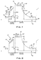
- FIGURE 1 shows an STT type waveform A for a short circuit welding process including a short condition 10, an arc condition 12, tailout 14 and background 16.
- This waveform is the current profile through the weld and is formed by a plurality of current pulses 20 created at a frequency exceeding 18 kHz.
- the widths of the current pulses control the magnitude or height of the waveform as illustrated in FIGURE 1.
- Short circuit welding includes alternating between an arc or plasma condition and a short condition initiated at the time a molten metal ball on the end of an electrode contacts the workpiece. This event occurs at time 30. Metal is then transferred from the electrode to the workpiece by surface tension action.
- pinch pulse 32 used to control the current with a profile having a rapidly increasing current section 32a, a break point 32b to give a second slope, and a premonition point 32c.
- a dv/dt, dr/dt or dp/dt circuit detects when the surface tension transfer of molten metal is ready to separate or explode. At that time, the voltage increases because the cross section decreases rapidly. This event anticipates the explosion or separation of the molten electrode tip from the workpiece.
- the waveform includes a current plunge section 32d before actual metal separation.
- Current pinch pulse 32 is controlled in the STT technology by the shape of pinch pulse 32 shown in FIGURE 1.
- the waveform implemented during arc condition 12 is a voltage waveform having a peak voltage V P and a background voltage V BK .
- V P peak voltage
- V BK background voltage
- the invention involves using current control during the short condition 10 and voltage control during arc position 12. In each instance, these controls follow predetermined waveforms to produce the desired characteristics. Consequently, the arc condition 12 is a voltage function.
- the voltage function is the voltage across the arc.
- Waveform A' includes a short condition 10' and an arc condition 12'.
- the voltage function used during condition 12' for closed loop control is wattage.
- the plasma boost pulse 40' and background 16' are peak wattage W P and background wattage W BK , respectively.
- the voltage function is sometimes joules, so a joules closed loop feedback produces a waveform as shown in FIGURES 1 and 2.
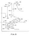
- Utilizing a pulse width modulated, inverter based power supply of the type used in the preferred embodiment of the present invention results in the current and voltage curves schematically illustrated in FIGURE 3.
- Current curve 100 plunges at time 102 when the molten metal ball is shorted to the workpiece causing the voltage to plunge. Such voltage decrease is to a level less than a reference voltage V R causing the power supply to shift from voltage control to current control.
- Current control implements the short portion of the weld cycle. The current is held down for a short time until time 104. Current control of the power supply is then released allowing a rapid increase in the current to create pinch pulse 110 having a break point 110a and a premonition point 110b.
- the current control of the power supply plunges the current as indicated by portion 110c.
- the explosion or metal separation occurs at the low current 106 that is maintained for a time t a .
- the current mode of operation allows an increase in voltage to create current pulse 120 which current is dictated by the predesigned voltage control waveform.
- Current pulse 120 has a steep, leading edge 122 during which the voltage is at the desired level while the current is advancing toward the upper peak current 124. This current level is caused by the set peak voltage used during voltage control of the power supply. Thereafter, current pulse 120 transitions into background portion of the arc condition along gradual curve 126.
- Pulse 120 is a current pulse with a shape dictated by the desired voltage waveform shown in the right portion of the voltage curve at the bottom portion of FIGURE 3.
- Current control defines pulse 110 and voltage control defines pulse 120.
- the voltage control experiences a short circuit and control is shifted from voltage to current. Thereafter, a low current is maintained until time 104.
- Current pulse 110 is then created by the desired current waveform. This control dictates the voltage variations that follows curve 160.
- the power supply maintains the desired shape of pinch pulse 110. Voltage immediately rises along portion 160a as a result of the desired current. At break point 110a, the voltage transitions along curve 160b until portion 160c where the voltage is plunged in response to the premonition signal. This is still in the current control mode.
- the shorted electrode separates at time 170, causing the voltage to increase to a level above reference V R causing the power supply to shift to a voltage control waveform level 172 as the arc voltage obtained when arc is reestablished at low current 106.
- This next waveform includes the peak voltage 174.
- Time T a plus time T b equals the previously discussed delay 34 having a time T x .
- the voltage transitions along portion 176 to the background voltage 178 where the voltage is held awaiting the next short circuit.
- 100 to 300 cycles of pulses shown in FIGURE 3 are performed each second.
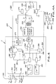
- welder 200 has a logic processor based controller C programmable to implement a short circuit arc welding process, such as an STT short circuit welding process.
- Inverter 202 has a standard rectified output circuit 204 for directing current through switch 206 and inductor 208 to electrode 210 in the form of an advancing wire used to weld workpiece 214.
- Voltage feedback 220 directs the level of the arc voltage back to digital controller C.
- shunt 222 directs the instantaneous arc current back to controller C by feedback line 224.
- the logic processor in controller C includes a digitally implemented pulse width modulator 230 having an input digitized error amplifier 232 with a waveform control represented by line 240. Pulse width modulator 230 causes inverter 202 to follow the waveform on line 240 based upon the feedback value in line 242.
- a current waveform generator 250 is provided to give the desired profile of the current pulse between the electrode and workpiece during various portions of the weld cycle.
- the current waveform generator 250 is used by pulse modulator 230 for only a portion of the time or segment of the weld cycle as determined by the conductive state of digital enable switch 252.
- generator 250 controls the logic on line 240 so that the feedback level on line 242 follows the desired precise current profile.
- a voltage waveform generator 260 is also provided.
- Generator 260 has an output directed through digital enable switch 262 to input 240.
- Switch 252 and switch 262 are anti-coincident. When one enable switch is closed, the other enable switch is opened.
- error amplifier 234 receives a waveform generated from either the current waveform generator 250 or the voltage waveform generator 260 according to the conductive condition of switch 252, 262.
- a premonition circuit 270 creates a logic in line 272 for opening switch 206 when the metal transfer is near the breaking point. Resistor 274 is then inserted into the weld circuit to reduce current along portion 110c.
- a digitized comparator 280 has a positive input 282 connected with the voltage feedback 220 and a negative input 284 controlled by reference voltage V R .
- Output line 290 of comparator 280 is connected to a voltage mold digital switch 292. The logic on line 290 is inverted by inverter 294 to provide the opposite logic on line 296 for controlling current mode switch 298.
- a logic 1 is created in line 290 for closing voltage mode switch 292 and enabling switch 262 so generator 260 controls the logic on line 240. At this same time, switches 252 and 298 are deactivated.
- the feedback voltage signal on line 220 is directed through switch 292 to input 242.
- inverter 202 follows waveform 150 of voltage waveform generator 260.
- This generator could also be a wattage waveform generator or a joules waveform generator. All of these iterations have been practiced to control the arc condition of the short circuit welding process.
- rheostat 300 adjusts the peak voltage or the peak wattage in the waveform of generator 260.
- rheostat 302 control the time constant for the tailout and rheostat 304 controls the background voltage or wattage for the waveform from generator 260.
- the logic scheme disclosed in FIGURE 4 is processed by digital technology in controller C and a variety of digital techniques can be used to accomplish the objective of generally operating the arc condition by a waveform tracking the desired function of voltage. In the past, the waveform during the arc condition has been merely an extension of the short circuit waveform so that the advantage of controlling the arc as a voltage function was not available.
- a digital switch is employed where the logic processor opens line 290 by a switch 290a illustrated in FIGURE 4A. This two pole switch concept grounds line 290b by ground 290c. This places a logic zero on line 290b to shift the switches to current control. This switch action is selected by the logic processor and is after the molten ball is formed by the plasma boost pulse.
- FIGURES 5 and 6 illustrate slight modifications of the block diagram and logic chart of FIGURE 4.
- the voltage function is wattage; therefore, the inputs of line 282 of comparator 280 is the product of the voltage feedback on line 220 and current feedback on line 224. These values are combined by the multiplier 210 to produce a value in line 312 representing the wattage feedback.
- the current feedback 224 is used at the input of switch 298 as previously shown in FIGURE 4.
- the arc condition is controlled by a wattage feedback while the short condition is controlled as shown in FIGURE 4 by a current feedback.
- the product in line 312 is integrated by integrator 320 to produce a joules feedback in line 322. This is directed to the positive input 282 of comparator 280 and to the input of switch 292 so the arc condition is controlled by a waveform that is a precise reflection of the desired joules.
Landscapes
- Engineering & Computer Science (AREA)
- Physics & Mathematics (AREA)
- Plasma & Fusion (AREA)
- Mechanical Engineering (AREA)
- Generation Of Surge Voltage And Current (AREA)
- Arc Welding Control (AREA)
Applications Claiming Priority (2)
| Application Number | Priority Date | Filing Date | Title |
|---|---|---|---|
| US766787 | 2001-01-23 | ||
| US09/766,787 US6501049B2 (en) | 2001-01-23 | 2001-01-23 | Short circuit arc welder and method of controlling same |
Publications (3)
| Publication Number | Publication Date |
|---|---|
| EP1232825A2 true EP1232825A2 (fr) | 2002-08-21 |
| EP1232825A3 EP1232825A3 (fr) | 2003-11-26 |
| EP1232825B1 EP1232825B1 (fr) | 2012-04-11 |
Family
ID=25077531
Family Applications (1)
| Application Number | Title | Priority Date | Filing Date |
|---|---|---|---|
| EP01129914A Expired - Lifetime EP1232825B1 (fr) | 2001-01-23 | 2001-12-15 | Dispositif de soudage à l'arc avec court-circuits et procédé de commande correspondant |
Country Status (11)
| Country | Link |
|---|---|
| US (1) | US6501049B2 (fr) |
| EP (1) | EP1232825B1 (fr) |
| JP (1) | JP2002273569A (fr) |
| KR (1) | KR100493125B1 (fr) |
| CN (1) | CN1203953C (fr) |
| AT (1) | ATE552933T1 (fr) |
| AU (1) | AU763707B2 (fr) |
| CA (1) | CA2364990C (fr) |
| NZ (1) | NZ515712A (fr) |
| RU (1) | RU2217274C2 (fr) |
| TW (1) | TW494044B (fr) |
Cited By (39)
| Publication number | Priority date | Publication date | Assignee | Title |
|---|---|---|---|---|
| EP1570937A2 (fr) | 2004-02-23 | 2005-09-07 | Lincoln Global, Inc. | Dispositif de soudage à l'arc avec court-circuits et procédé de commande correspondant |
| DE102004007059A1 (de) * | 2004-02-13 | 2005-09-08 | Ewm Hightec Welding Gmbh | Verfahren zur Steuerung eines Schweißgerätes zum MSG (Metall-Schutzgas-Lichtbogen)-Schweißen |
| EP1607162A1 (fr) * | 2004-06-04 | 2005-12-21 | Lincoln Global, Inc. | Dispositif pour le soudage à l'arc pulsé et procédé d'utilisation |
| EP1710037A1 (fr) * | 2005-04-05 | 2006-10-11 | Vermaat Technics B.V. | Dispositif et méthode de soudage à l'arc court-circuit |
| DE102005024802A1 (de) * | 2005-05-27 | 2006-11-30 | Ewm Hightec Welding Gmbh | Schweissstromquelle und Verfahren zum MIG/MAG-Schweissen |
| WO2007126507A1 (fr) * | 2006-03-31 | 2007-11-08 | Illinois Tool Works Inc. | Procédé et appareil de soudage par impulsions |
| EP2862661A4 (fr) * | 2012-06-18 | 2016-01-27 | Panasonic Ip Man Co Ltd | Procédé de soudage à l'arc et appareil de soudage à l'arc |
| WO2016043904A1 (fr) * | 2014-09-17 | 2016-03-24 | Illinois Tool Works Inc. | Système et procédé de soudage par impulsions à électrode négative |
| US9393635B2 (en) | 2004-06-04 | 2016-07-19 | Lincoln Global, Inc. | Adaptive GMAW short circuit frequency control and high deposition arc welding |
| US9950383B2 (en) | 2013-02-05 | 2018-04-24 | Illinois Tool Works Inc. | Welding wire preheating system and method |
| US10040143B2 (en) | 2012-12-12 | 2018-08-07 | Illinois Tool Works Inc. | Dabbing pulsed welding system and method |
| EP3366402A1 (fr) * | 2017-01-27 | 2018-08-29 | Lincoln Global, Inc. | Appareil et procédé de soudage ayant une forme d'ondes ca |
| US10189106B2 (en) | 2014-12-11 | 2019-01-29 | Illinois Tool Works Inc. | Reduced energy welding system and method |
| US10610946B2 (en) | 2015-12-07 | 2020-04-07 | Illinois Tool Works, Inc. | Systems and methods for automated root pass welding |
| US10675699B2 (en) | 2015-12-10 | 2020-06-09 | Illinois Tool Works Inc. | Systems, methods, and apparatus to preheat welding wire |
| US10682719B2 (en) | 2017-01-27 | 2020-06-16 | Lincoln Global, Inc. | Apparatus and method for welding with AC waveform |
| US10722967B2 (en) | 2017-01-27 | 2020-07-28 | Lincoln Global, Inc. | Apparatus and method for welding with AC waveform |
| US10744584B2 (en) | 2017-01-27 | 2020-08-18 | Lincoln Global, Inc. | Apparatus and method for welding with AC waveform |
| US10766092B2 (en) | 2017-04-18 | 2020-09-08 | Illinois Tool Works Inc. | Systems, methods, and apparatus to provide preheat voltage feedback loss protection |
| US10828728B2 (en) | 2013-09-26 | 2020-11-10 | Illinois Tool Works Inc. | Hotwire deposition material processing system and method |
| US10835983B2 (en) | 2013-03-14 | 2020-11-17 | Illinois Tool Works Inc. | Electrode negative pulse welding system and method |
| US10870164B2 (en) | 2017-05-16 | 2020-12-22 | Illinois Tool Works Inc. | Systems, methods, and apparatus to preheat welding wire |
| US10906114B2 (en) | 2012-12-21 | 2021-02-02 | Illinois Tool Works Inc. | System for arc welding with enhanced metal deposition |
| US10926349B2 (en) | 2017-06-09 | 2021-02-23 | Illinois Tool Works Inc. | Systems, methods, and apparatus to preheat welding wire |
| US11014185B2 (en) | 2018-09-27 | 2021-05-25 | Illinois Tool Works Inc. | Systems, methods, and apparatus for control of wire preheating in welding-type systems |
| US11020813B2 (en) | 2017-09-13 | 2021-06-01 | Illinois Tool Works Inc. | Systems, methods, and apparatus to reduce cast in a welding wire |
| US11045891B2 (en) | 2013-06-13 | 2021-06-29 | Illinois Tool Works Inc. | Systems and methods for anomalous cathode event control |
| US11154946B2 (en) | 2014-06-30 | 2021-10-26 | Illinois Tool Works Inc. | Systems and methods for the control of welding parameters |
| US11247290B2 (en) | 2017-06-09 | 2022-02-15 | Illinois Tool Works Inc. | Systems, methods, and apparatus to preheat welding wire |
| US11285559B2 (en) | 2015-11-30 | 2022-03-29 | Illinois Tool Works Inc. | Welding system and method for shielded welding wires |
| US11370050B2 (en) | 2015-03-31 | 2022-06-28 | Illinois Tool Works Inc. | Controlled short circuit welding system and method |
| US11478870B2 (en) | 2014-11-26 | 2022-10-25 | Illinois Tool Works Inc. | Dabbing pulsed welding system and method |
| US11524354B2 (en) | 2017-06-09 | 2022-12-13 | Illinois Tool Works Inc. | Systems, methods, and apparatus to control weld current in a preheating system |
| US11590598B2 (en) | 2017-06-09 | 2023-02-28 | Illinois Tool Works Inc. | Systems, methods, and apparatus to preheat welding wire |
| US11590597B2 (en) | 2017-06-09 | 2023-02-28 | Illinois Tool Works Inc. | Systems, methods, and apparatus to preheat welding wire |
| US11654503B2 (en) | 2018-08-31 | 2023-05-23 | Illinois Tool Works Inc. | Submerged arc welding systems and submerged arc welding torches to resistively preheat electrode wire |
| US11772182B2 (en) | 2019-12-20 | 2023-10-03 | Illinois Tool Works Inc. | Systems and methods for gas control during welding wire pretreatments |
| US11897062B2 (en) | 2018-12-19 | 2024-02-13 | Illinois Tool Works Inc. | Systems, methods, and apparatus to preheat welding wire |
| US12103121B2 (en) | 2019-04-30 | 2024-10-01 | Illinois Tool Works Inc. | Methods and apparatus to control welding power and preheating power |
Families Citing this family (52)
| Publication number | Priority date | Publication date | Assignee | Title |
|---|---|---|---|---|
| US6717107B1 (en) * | 2001-05-29 | 2004-04-06 | Lincoln Global, Inc. | Two stage welder and method of operating same |
| US6969823B2 (en) | 2002-07-23 | 2005-11-29 | Illinois Tool Works Inc. | Method and apparatus for controlling a welding system |
| US6974932B2 (en) * | 2003-03-31 | 2005-12-13 | Illinois Tool Works Inc. | Method and apparatus for welding |
| US6942139B2 (en) * | 2003-04-29 | 2005-09-13 | Lincoln Global, Inc. | Robotic cylinder welding |
| US7053334B2 (en) * | 2004-03-01 | 2006-05-30 | Lincoln Global, Inc. | Electric arc welder system with waveform profile control |
| US7166817B2 (en) * | 2004-04-29 | 2007-01-23 | Lincoln Global, Inc. | Electric ARC welder system with waveform profile control for cored electrodes |
| US8704135B2 (en) | 2006-01-20 | 2014-04-22 | Lincoln Global, Inc. | Synergistic welding system |
| US8759715B2 (en) * | 2004-10-06 | 2014-06-24 | Lincoln Global, Inc. | Method of AC welding with cored electrode |
| US9333580B2 (en) * | 2004-04-29 | 2016-05-10 | Lincoln Global, Inc. | Gas-less process and system for girth welding in high strength applications |
| US7842903B2 (en) | 2005-10-31 | 2010-11-30 | Lincoln Global, Inc. | Short arc welding system |
| US20070221643A1 (en) * | 2004-04-29 | 2007-09-27 | Lincoln Global, Inc. | Gas-less process and system for girth welding in high strength applications including liquefied natural gas storage tanks |
| US8203099B2 (en) * | 2004-06-04 | 2012-06-19 | Lincoln Global, Inc. | Method and device to build-up, clad, or hard-face with minimal admixture |
| US8581147B2 (en) | 2005-03-24 | 2013-11-12 | Lincoln Global, Inc. | Three stage power source for electric ARC welding |
| US9956639B2 (en) | 2005-02-07 | 2018-05-01 | Lincoln Global, Inc | Modular power source for electric ARC welding and output chopper |
| US8269141B2 (en) | 2004-07-13 | 2012-09-18 | Lincoln Global, Inc. | Power source for electric arc welding |
| US8785816B2 (en) * | 2004-07-13 | 2014-07-22 | Lincoln Global, Inc. | Three stage power source for electric arc welding |
| US9855620B2 (en) | 2005-02-07 | 2018-01-02 | Lincoln Global, Inc. | Welding system and method of welding |
| US7495193B2 (en) * | 2005-03-15 | 2009-02-24 | Lincoln Global, Inc. | Pipe seam tack welding methods and apparatus using modified series arc welding |
| US7968822B2 (en) * | 2005-03-28 | 2011-06-28 | Lincoln Global, Inc. | Arc welding system |
| US9647555B2 (en) | 2005-04-08 | 2017-05-09 | Lincoln Global, Inc. | Chopper output stage for arc welder power source |
| US7271365B2 (en) * | 2005-04-11 | 2007-09-18 | Lincoln Global, Inc. | System and method for pulse welding |
| US20060231540A1 (en) * | 2005-04-19 | 2006-10-19 | Lincoln Global, Inc. | Method and apparatus for short-circuit welding |
| US8680432B2 (en) * | 2005-04-20 | 2014-03-25 | Illinois Tool Works Inc. | Cooperative welding system |
| JP3844004B1 (ja) * | 2005-05-31 | 2006-11-08 | 松下電器産業株式会社 | パルスアーク溶接制御方法及びパルスアーク溶接装置 |
| US7989732B2 (en) * | 2005-06-15 | 2011-08-02 | Lincoln Global, Inc. | Method of AC welding using a flux cored electrode |
| FI119592B (fi) * | 2005-09-06 | 2009-01-15 | Kemppi Oy | Menetelmä ja laitteisto hitsausta varten |
| FI119923B (fi) * | 2005-09-08 | 2009-05-15 | Kemppi Oy | Menetelmä ja laitteisto lyhytkaarihitsausta varten |
| PL1924384T3 (pl) * | 2005-09-12 | 2014-01-31 | Esab Ab | Sposób sterowania spawaniem MIG/MAG i urządzenie spawalnicze stosujące tę metodę |
| US20080053978A1 (en) | 2006-08-29 | 2008-03-06 | Lincoln Global, Inc. | Welder with positional heat control and method of using same |
| US20080264917A1 (en) * | 2007-04-30 | 2008-10-30 | Illinois Tool Works Inc. | Metal core welding wire pulsed welding system and method |
| US9895760B2 (en) * | 2007-09-26 | 2018-02-20 | Lincoln Global, Inc. | Method and system to increase heat input to a weld during a short-circuit arc welding process |
| US8373093B2 (en) * | 2008-06-27 | 2013-02-12 | Lincoln Global, Inc. | Method and system to increase heat input to a weld during a short-circuit arc welding process |
| US9415458B2 (en) * | 2007-09-26 | 2016-08-16 | Lincoln Global, Inc. | Method to improve the characteristics of a root pass pipe weld |
| US20090261073A1 (en) * | 2008-04-22 | 2009-10-22 | Lincoln Global, Inc. | System and methods of using variable waveform ac arc welding to achieve specific weld metal chemistries |
| CN102123812B (zh) * | 2009-04-08 | 2013-06-12 | 松下电器产业株式会社 | 电弧焊接方法及电弧焊接装置 |
| JP5770047B2 (ja) * | 2011-08-25 | 2015-08-26 | 株式会社ダイヘン | 溶接装置 |
| JP5912356B2 (ja) * | 2011-09-14 | 2016-04-27 | 株式会社ダイヘン | 溶接装置 |
| US9403233B2 (en) | 2011-12-16 | 2016-08-02 | Illinois Tool Works Inc. | DC electrode negative rotating arc welding method and system |
| US20130264323A1 (en) * | 2012-04-05 | 2013-10-10 | Lincoln Global, Inc. | Process for surface tension transfer short ciruit welding |
| US10046410B2 (en) | 2012-07-19 | 2018-08-14 | Lincoln Global Inc. | Apparatus and method for modulating heat input during welding |
| US9511442B2 (en) | 2012-07-27 | 2016-12-06 | Illinois Tool Works Inc. | Adaptable rotating arc welding method and system |
| US9352410B2 (en) | 2013-03-15 | 2016-05-31 | Lincoln Global, Inc. | System for and method of narrow-groove joining of metals |
| US10953484B2 (en) | 2013-09-16 | 2021-03-23 | Illinois Tool Works Inc. | Narrow groove welding method and system |
| US10543551B2 (en) | 2013-09-16 | 2020-01-28 | Illinois Tool Works Inc. | Synchronized rotating arc welding method and system |
| RU2613247C2 (ru) * | 2015-07-13 | 2017-03-15 | Сергей Валентинович Федюкин | Способ механизированной дуговой сварки с короткими замыканиями в среде инертных и защитных газов |
| US10179369B2 (en) | 2015-10-27 | 2019-01-15 | Lincoln Global, Inc. | Welding system for AC welding with reduced spatter |
| EP3412396B1 (fr) * | 2016-02-04 | 2021-09-15 | Panasonic Intellectual Property Management Co., Ltd. | Procédé de commande de soudage à arc pulsé et dispositif de soudage à arc pulsé |
| US20190030635A1 (en) * | 2017-07-28 | 2019-01-31 | Lincoln Global, Inc. | Welding power supply identification of remote switch operation |
| CN108890082B (zh) * | 2018-07-19 | 2020-07-24 | 唐山松下产业机器有限公司 | 电弧焊接控制方法和装置、以及焊接设备 |
| US11370051B2 (en) * | 2018-10-30 | 2022-06-28 | Lincoln Global, Inc. | Time-based short circuit response |
| US11311958B1 (en) * | 2019-05-13 | 2022-04-26 | Airgas, Inc. | Digital welding and cutting efficiency analysis, process evaluation and response feedback system for process optimization |
| RU2736144C1 (ru) * | 2020-01-10 | 2020-11-11 | Сергей Валентинович Федюкин | Способ дуговой сварки плавящимся электродом в среде защитных газов |
Citations (2)
| Publication number | Priority date | Publication date | Assignee | Title |
|---|---|---|---|---|
| US4866247A (en) * | 1986-12-11 | 1989-09-12 | The Lincoln Electric Company | Apparatus and method of short circuiting arc welding |
| US6015964A (en) * | 1998-08-03 | 2000-01-18 | Lincoln Global, Inc. | Electric arc welder with controlled arc |
Family Cites Families (13)
| Publication number | Priority date | Publication date | Assignee | Title |
|---|---|---|---|---|
| GB1112511A (en) | 1965-03-11 | 1968-05-08 | Lincoln Electric Company Ltd | Improvements in or relating to electric arc welding apparatus |
| GB1399101A (en) | 1971-08-24 | 1975-06-25 | Welding Inst | Arc welding apparatus |
| US3809853A (en) * | 1972-08-24 | 1974-05-07 | Union Carbide Corp | Method for short circuit metal transfer arc welding |
| NL176060B (nl) | 1974-02-08 | 1984-09-17 | Philips Nv | Lasinrichting voor kortsluitbooglassen. |
| US4125759A (en) * | 1974-10-17 | 1978-11-14 | Osaka Transformer Co., Ltd. | Method and apparatus for shortcircuiting arc welding |
| GB2101427B (en) * | 1981-04-10 | 1985-10-23 | Mitsubishi Electric Corp | Short circuit transfer arc welding machine |
| GB8306578D0 (en) * | 1983-03-10 | 1983-04-13 | Welding Inst | Short-circuit mig welding |
| US4546234A (en) | 1983-08-11 | 1985-10-08 | Kabushiki Kaisha Kobe Seiko Sho | Output control of short circuit welding power source |
| US5148001A (en) | 1986-12-11 | 1992-09-15 | The Lincoln Electric Company | System and method of short circuiting arc welding |
| US5001326A (en) * | 1986-12-11 | 1991-03-19 | The Lincoln Electric Company | Apparatus and method of controlling a welding cycle |
| KR910004964B1 (ko) * | 1987-04-28 | 1991-07-20 | 마쯔시다덴기산교 가부시기가이샤 | 소모전극식 아아크용접기 |
| US5278390A (en) | 1993-03-18 | 1994-01-11 | The Lincoln Electric Company | System and method for controlling a welding process for an arc welder |
| US6051810A (en) | 1998-01-09 | 2000-04-18 | Lincoln Global, Inc. | Short circuit welder |
-
2001
- 2001-01-23 US US09/766,787 patent/US6501049B2/en not_active Expired - Lifetime
- 2001-11-26 NZ NZ515712A patent/NZ515712A/xx unknown
- 2001-11-26 TW TW090129202A patent/TW494044B/zh not_active IP Right Cessation
- 2001-12-04 RU RU2001132549/02A patent/RU2217274C2/ru not_active IP Right Cessation
- 2001-12-05 AU AU97089/01A patent/AU763707B2/en not_active Ceased
- 2001-12-11 CN CNB011402822A patent/CN1203953C/zh not_active Expired - Lifetime
- 2001-12-13 CA CA002364990A patent/CA2364990C/fr not_active Expired - Fee Related
- 2001-12-15 EP EP01129914A patent/EP1232825B1/fr not_active Expired - Lifetime
- 2001-12-15 AT AT01129914T patent/ATE552933T1/de active
-
2002
- 2002-01-22 KR KR10-2002-0003603A patent/KR100493125B1/ko not_active IP Right Cessation
- 2002-01-23 JP JP2002013827A patent/JP2002273569A/ja active Pending
Patent Citations (2)
| Publication number | Priority date | Publication date | Assignee | Title |
|---|---|---|---|---|
| US4866247A (en) * | 1986-12-11 | 1989-09-12 | The Lincoln Electric Company | Apparatus and method of short circuiting arc welding |
| US6015964A (en) * | 1998-08-03 | 2000-01-18 | Lincoln Global, Inc. | Electric arc welder with controlled arc |
Cited By (56)
| Publication number | Priority date | Publication date | Assignee | Title |
|---|---|---|---|---|
| DE102004007059A1 (de) * | 2004-02-13 | 2005-09-08 | Ewm Hightec Welding Gmbh | Verfahren zur Steuerung eines Schweißgerätes zum MSG (Metall-Schutzgas-Lichtbogen)-Schweißen |
| EP1570937A2 (fr) | 2004-02-23 | 2005-09-07 | Lincoln Global, Inc. | Dispositif de soudage à l'arc avec court-circuits et procédé de commande correspondant |
| EP1570937A3 (fr) * | 2004-02-23 | 2008-01-02 | Lincoln Global, Inc. | Dispositif de soudage à l'arc avec court-circuits et procédé de commande correspondant |
| US8283598B2 (en) | 2004-06-04 | 2012-10-09 | Lincoln Global, Inc. | Pulse welder and method utilizing a plasma boost |
| EP1607162A1 (fr) * | 2004-06-04 | 2005-12-21 | Lincoln Global, Inc. | Dispositif pour le soudage à l'arc pulsé et procédé d'utilisation |
| US9393635B2 (en) | 2004-06-04 | 2016-07-19 | Lincoln Global, Inc. | Adaptive GMAW short circuit frequency control and high deposition arc welding |
| US7304269B2 (en) | 2004-06-04 | 2007-12-04 | Lincoln Global, Inc. | Pulse welder and method of using same |
| EP1710037A1 (fr) * | 2005-04-05 | 2006-10-11 | Vermaat Technics B.V. | Dispositif et méthode de soudage à l'arc court-circuit |
| DE102005024802A1 (de) * | 2005-05-27 | 2006-11-30 | Ewm Hightec Welding Gmbh | Schweissstromquelle und Verfahren zum MIG/MAG-Schweissen |
| WO2007126507A1 (fr) * | 2006-03-31 | 2007-11-08 | Illinois Tool Works Inc. | Procédé et appareil de soudage par impulsions |
| EP2862661A4 (fr) * | 2012-06-18 | 2016-01-27 | Panasonic Ip Man Co Ltd | Procédé de soudage à l'arc et appareil de soudage à l'arc |
| US9776273B2 (en) | 2012-06-18 | 2017-10-03 | Panasonic Intellectual Property Management Co., Ltd. | Arc-welding method and arc-welding apparatus |
| US10654121B2 (en) | 2012-06-18 | 2020-05-19 | Panasonic Intellectual Property Management Co., Ltd. | Arc-welding method and arc-welding apparatus |
| US10040143B2 (en) | 2012-12-12 | 2018-08-07 | Illinois Tool Works Inc. | Dabbing pulsed welding system and method |
| US10906114B2 (en) | 2012-12-21 | 2021-02-02 | Illinois Tool Works Inc. | System for arc welding with enhanced metal deposition |
| US11878376B2 (en) | 2013-02-05 | 2024-01-23 | Illinois Tool Works Inc. | Welding wire preheating systems and methods |
| US11040410B2 (en) | 2013-02-05 | 2021-06-22 | Illinois Tool Works Inc. | Welding wire preheating systems and methods |
| US9950383B2 (en) | 2013-02-05 | 2018-04-24 | Illinois Tool Works Inc. | Welding wire preheating system and method |
| US10835984B2 (en) | 2013-03-14 | 2020-11-17 | Illinois Tool Works Inc. | Electrode negative pulse welding system and method |
| US10835983B2 (en) | 2013-03-14 | 2020-11-17 | Illinois Tool Works Inc. | Electrode negative pulse welding system and method |
| US11045891B2 (en) | 2013-06-13 | 2021-06-29 | Illinois Tool Works Inc. | Systems and methods for anomalous cathode event control |
| US10828728B2 (en) | 2013-09-26 | 2020-11-10 | Illinois Tool Works Inc. | Hotwire deposition material processing system and method |
| US11154946B2 (en) | 2014-06-30 | 2021-10-26 | Illinois Tool Works Inc. | Systems and methods for the control of welding parameters |
| CN107073624A (zh) * | 2014-09-17 | 2017-08-18 | 伊利诺斯工具制品有限公司 | 反接脉冲焊接系统和方法 |
| WO2016043904A1 (fr) * | 2014-09-17 | 2016-03-24 | Illinois Tool Works Inc. | Système et procédé de soudage par impulsions à électrode négative |
| US11198189B2 (en) | 2014-09-17 | 2021-12-14 | Illinois Tool Works Inc. | Electrode negative pulse welding system and method |
| US11478870B2 (en) | 2014-11-26 | 2022-10-25 | Illinois Tool Works Inc. | Dabbing pulsed welding system and method |
| US11253940B2 (en) | 2014-12-11 | 2022-02-22 | Illinois Tool Works Inc. | Reduced energy welding system and method |
| US10189106B2 (en) | 2014-12-11 | 2019-01-29 | Illinois Tool Works Inc. | Reduced energy welding system and method |
| US11370050B2 (en) | 2015-03-31 | 2022-06-28 | Illinois Tool Works Inc. | Controlled short circuit welding system and method |
| US11285559B2 (en) | 2015-11-30 | 2022-03-29 | Illinois Tool Works Inc. | Welding system and method for shielded welding wires |
| US10610946B2 (en) | 2015-12-07 | 2020-04-07 | Illinois Tool Works, Inc. | Systems and methods for automated root pass welding |
| US11766732B2 (en) | 2015-12-07 | 2023-09-26 | Illinois Tool Works Inc. | Systems and methods for automated root pass welding |
| US10675699B2 (en) | 2015-12-10 | 2020-06-09 | Illinois Tool Works Inc. | Systems, methods, and apparatus to preheat welding wire |
| EP3366402A1 (fr) * | 2017-01-27 | 2018-08-29 | Lincoln Global, Inc. | Appareil et procédé de soudage ayant une forme d'ondes ca |
| US11110536B2 (en) | 2017-01-27 | 2021-09-07 | Lincoln Global, Inc. | Apparatus and method for welding with AC waveform |
| US10744584B2 (en) | 2017-01-27 | 2020-08-18 | Lincoln Global, Inc. | Apparatus and method for welding with AC waveform |
| US10722967B2 (en) | 2017-01-27 | 2020-07-28 | Lincoln Global, Inc. | Apparatus and method for welding with AC waveform |
| US10682719B2 (en) | 2017-01-27 | 2020-06-16 | Lincoln Global, Inc. | Apparatus and method for welding with AC waveform |
| US11911859B2 (en) | 2017-04-18 | 2024-02-27 | Illinois Tool Works Inc. | Systems, methods, and apparatus to provide preheat voltage feedback loss protection |
| US10766092B2 (en) | 2017-04-18 | 2020-09-08 | Illinois Tool Works Inc. | Systems, methods, and apparatus to provide preheat voltage feedback loss protection |
| US10870164B2 (en) | 2017-05-16 | 2020-12-22 | Illinois Tool Works Inc. | Systems, methods, and apparatus to preheat welding wire |
| US11819959B2 (en) | 2017-05-16 | 2023-11-21 | Illinois Tool Works Inc. | Systems, methods, and apparatus to preheat welding wire |
| US10926349B2 (en) | 2017-06-09 | 2021-02-23 | Illinois Tool Works Inc. | Systems, methods, and apparatus to preheat welding wire |
| US11524354B2 (en) | 2017-06-09 | 2022-12-13 | Illinois Tool Works Inc. | Systems, methods, and apparatus to control weld current in a preheating system |
| US11590598B2 (en) | 2017-06-09 | 2023-02-28 | Illinois Tool Works Inc. | Systems, methods, and apparatus to preheat welding wire |
| US11590597B2 (en) | 2017-06-09 | 2023-02-28 | Illinois Tool Works Inc. | Systems, methods, and apparatus to preheat welding wire |
| US11980977B2 (en) | 2017-06-09 | 2024-05-14 | Illinois Tool Works Inc. | Systems, methods, and apparatus to control weld current in a preheating system |
| US11247290B2 (en) | 2017-06-09 | 2022-02-15 | Illinois Tool Works Inc. | Systems, methods, and apparatus to preheat welding wire |
| US11020813B2 (en) | 2017-09-13 | 2021-06-01 | Illinois Tool Works Inc. | Systems, methods, and apparatus to reduce cast in a welding wire |
| US11654503B2 (en) | 2018-08-31 | 2023-05-23 | Illinois Tool Works Inc. | Submerged arc welding systems and submerged arc welding torches to resistively preheat electrode wire |
| US11014185B2 (en) | 2018-09-27 | 2021-05-25 | Illinois Tool Works Inc. | Systems, methods, and apparatus for control of wire preheating in welding-type systems |
| US11897062B2 (en) | 2018-12-19 | 2024-02-13 | Illinois Tool Works Inc. | Systems, methods, and apparatus to preheat welding wire |
| US12103121B2 (en) | 2019-04-30 | 2024-10-01 | Illinois Tool Works Inc. | Methods and apparatus to control welding power and preheating power |
| US11772182B2 (en) | 2019-12-20 | 2023-10-03 | Illinois Tool Works Inc. | Systems and methods for gas control during welding wire pretreatments |
| US12059758B2 (en) | 2019-12-20 | 2024-08-13 | Illinois Tool Works Inc. | Methods and systems for gas control during welding wire pretreatments |
Also Published As
| Publication number | Publication date |
|---|---|
| AU763707B2 (en) | 2003-07-31 |
| ATE552933T1 (de) | 2012-04-15 |
| EP1232825A3 (fr) | 2003-11-26 |
| RU2217274C2 (ru) | 2003-11-27 |
| CA2364990A1 (fr) | 2002-07-23 |
| KR20020062697A (ko) | 2002-07-29 |
| CA2364990C (fr) | 2004-04-06 |
| JP2002273569A (ja) | 2002-09-25 |
| TW494044B (en) | 2002-07-11 |
| NZ515712A (en) | 2003-04-29 |
| AU9708901A (en) | 2002-07-25 |
| CN1367059A (zh) | 2002-09-04 |
| CN1203953C (zh) | 2005-06-01 |
| US6501049B2 (en) | 2002-12-31 |
| EP1232825B1 (fr) | 2012-04-11 |
| US20020125235A1 (en) | 2002-09-12 |
| KR100493125B1 (ko) | 2005-06-03 |
Similar Documents
| Publication | Publication Date | Title |
|---|---|---|
| EP1232825B1 (fr) | Dispositif de soudage à l'arc avec court-circuits et procédé de commande correspondant | |
| EP1570937B1 (fr) | Dispositif de soudage à l'arc avec court-circuits | |
| JP3203386U (ja) | 一定溶滴サイズのための可変極性パルス | |
| US7842903B2 (en) | Short arc welding system | |
| US6326591B1 (en) | Method and apparatus for short arc welding | |
| US8492678B2 (en) | Method and apparatus for short-circuit welding utilizing cycle history | |
| EP1249297B1 (fr) | Procédé et système pour la commande d'un appareil de soudage à l'arc électrique | |
| JPS60223660A (ja) | ア−ク溶接法 |
Legal Events
| Date | Code | Title | Description |
|---|---|---|---|
| PUAI | Public reference made under article 153(3) epc to a published international application that has entered the european phase |
Free format text: ORIGINAL CODE: 0009012 |
|
| AK | Designated contracting states |
Kind code of ref document: A2 Designated state(s): AT BE CH CY DE DK ES FI FR GB GR IE IT LI LU MC NL PT SE TR |
|
| AX | Request for extension of the european patent |
Free format text: AL;LT;LV;MK;RO;SI |
|
| PUAL | Search report despatched |
Free format text: ORIGINAL CODE: 0009013 |
|
| AK | Designated contracting states |
Kind code of ref document: A3 Designated state(s): AT BE CH CY DE DK ES FI FR GB GR IE IT LI LU MC NL PT SE TR |
|
| AX | Request for extension of the european patent |
Extension state: AL LT LV MK RO SI |
|
| 17P | Request for examination filed |
Effective date: 20031107 |
|
| AKX | Designation fees paid |
Designated state(s): AT BE CH CY DE DK ES FI FR GB GR IE IT LI LU MC NL PT SE TR |
|
| 17Q | First examination report despatched |
Effective date: 20050215 |
|
| RAP1 | Party data changed (applicant data changed or rights of an application transferred) |
Owner name: LINCOLN GLOBAL, INC. |
|
| 17Q | First examination report despatched |
Effective date: 20050215 |
|
| RAP1 | Party data changed (applicant data changed or rights of an application transferred) |
Owner name: LINCOLN GLOBAL, INC. |
|
| GRAP | Despatch of communication of intention to grant a patent |
Free format text: ORIGINAL CODE: EPIDOSNIGR1 |
|
| GRAS | Grant fee paid |
Free format text: ORIGINAL CODE: EPIDOSNIGR3 |
|
| GRAA | (expected) grant |
Free format text: ORIGINAL CODE: 0009210 |
|
| AK | Designated contracting states |
Kind code of ref document: B1 Designated state(s): AT BE CH CY DE DK ES FI FR GB GR IE IT LI LU MC NL PT SE TR |
|
| REG | Reference to a national code |
Ref country code: GB Ref legal event code: FG4D |
|
| REG | Reference to a national code |
Ref country code: CH Ref legal event code: EP |
|
| REG | Reference to a national code |
Ref country code: AT Ref legal event code: REF Ref document number: 552933 Country of ref document: AT Kind code of ref document: T Effective date: 20120415 |
|
| REG | Reference to a national code |
Ref country code: IE Ref legal event code: FG4D |
|
| REG | Reference to a national code |
Ref country code: DE Ref legal event code: R096 Ref document number: 60146366 Country of ref document: DE Effective date: 20120606 |
|
| REG | Reference to a national code |
Ref country code: NL Ref legal event code: VDEP Effective date: 20120411 |
|
| REG | Reference to a national code |
Ref country code: SE Ref legal event code: TRGR |
|
| PG25 | Lapsed in a contracting state [announced via postgrant information from national office to epo] |
Ref country code: FI Free format text: LAPSE BECAUSE OF FAILURE TO SUBMIT A TRANSLATION OF THE DESCRIPTION OR TO PAY THE FEE WITHIN THE PRESCRIBED TIME-LIMIT Effective date: 20120411 Ref country code: CY Free format text: LAPSE BECAUSE OF FAILURE TO SUBMIT A TRANSLATION OF THE DESCRIPTION OR TO PAY THE FEE WITHIN THE PRESCRIBED TIME-LIMIT Effective date: 20120411 |
|
| PG25 | Lapsed in a contracting state [announced via postgrant information from national office to epo] |
Ref country code: GR Free format text: LAPSE BECAUSE OF FAILURE TO SUBMIT A TRANSLATION OF THE DESCRIPTION OR TO PAY THE FEE WITHIN THE PRESCRIBED TIME-LIMIT Effective date: 20120712 Ref country code: PT Free format text: LAPSE BECAUSE OF FAILURE TO SUBMIT A TRANSLATION OF THE DESCRIPTION OR TO PAY THE FEE WITHIN THE PRESCRIBED TIME-LIMIT Effective date: 20120813 |
|
| PG25 | Lapsed in a contracting state [announced via postgrant information from national office to epo] |
Ref country code: BE Free format text: LAPSE BECAUSE OF FAILURE TO SUBMIT A TRANSLATION OF THE DESCRIPTION OR TO PAY THE FEE WITHIN THE PRESCRIBED TIME-LIMIT Effective date: 20120411 |
|
| PG25 | Lapsed in a contracting state [announced via postgrant information from national office to epo] |
Ref country code: NL Free format text: LAPSE BECAUSE OF FAILURE TO SUBMIT A TRANSLATION OF THE DESCRIPTION OR TO PAY THE FEE WITHIN THE PRESCRIBED TIME-LIMIT Effective date: 20120411 Ref country code: DK Free format text: LAPSE BECAUSE OF FAILURE TO SUBMIT A TRANSLATION OF THE DESCRIPTION OR TO PAY THE FEE WITHIN THE PRESCRIBED TIME-LIMIT Effective date: 20120411 |
|
| PLBE | No opposition filed within time limit |
Free format text: ORIGINAL CODE: 0009261 |
|
| STAA | Information on the status of an ep patent application or granted ep patent |
Free format text: STATUS: NO OPPOSITION FILED WITHIN TIME LIMIT |
|
| 26N | No opposition filed |
Effective date: 20130114 |
|
| PG25 | Lapsed in a contracting state [announced via postgrant information from national office to epo] |
Ref country code: ES Free format text: LAPSE BECAUSE OF FAILURE TO SUBMIT A TRANSLATION OF THE DESCRIPTION OR TO PAY THE FEE WITHIN THE PRESCRIBED TIME-LIMIT Effective date: 20120722 |
|
| REG | Reference to a national code |
Ref country code: DE Ref legal event code: R097 Ref document number: 60146366 Country of ref document: DE Effective date: 20130114 |
|
| PG25 | Lapsed in a contracting state [announced via postgrant information from national office to epo] |
Ref country code: MC Free format text: LAPSE BECAUSE OF NON-PAYMENT OF DUE FEES Effective date: 20121231 |
|
| REG | Reference to a national code |
Ref country code: CH Ref legal event code: PL |
|
| GBPC | Gb: european patent ceased through non-payment of renewal fee |
Effective date: 20121215 |
|
| REG | Reference to a national code |
Ref country code: IE Ref legal event code: MM4A |
|
| PG25 | Lapsed in a contracting state [announced via postgrant information from national office to epo] |
Ref country code: LI Free format text: LAPSE BECAUSE OF NON-PAYMENT OF DUE FEES Effective date: 20121231 Ref country code: CH Free format text: LAPSE BECAUSE OF NON-PAYMENT OF DUE FEES Effective date: 20121231 Ref country code: IE Free format text: LAPSE BECAUSE OF NON-PAYMENT OF DUE FEES Effective date: 20121215 |
|
| PG25 | Lapsed in a contracting state [announced via postgrant information from national office to epo] |
Ref country code: GB Free format text: LAPSE BECAUSE OF NON-PAYMENT OF DUE FEES Effective date: 20121215 |
|
| PGFP | Annual fee paid to national office [announced via postgrant information from national office to epo] |
Ref country code: AT Payment date: 20131120 Year of fee payment: 13 Ref country code: SE Payment date: 20131230 Year of fee payment: 13 |
|
| PGFP | Annual fee paid to national office [announced via postgrant information from national office to epo] |
Ref country code: IT Payment date: 20131223 Year of fee payment: 13 Ref country code: FR Payment date: 20131217 Year of fee payment: 13 |
|
| PG25 | Lapsed in a contracting state [announced via postgrant information from national office to epo] |
Ref country code: TR Free format text: LAPSE BECAUSE OF FAILURE TO SUBMIT A TRANSLATION OF THE DESCRIPTION OR TO PAY THE FEE WITHIN THE PRESCRIBED TIME-LIMIT Effective date: 20120411 |
|
| PG25 | Lapsed in a contracting state [announced via postgrant information from national office to epo] |
Ref country code: LU Free format text: LAPSE BECAUSE OF NON-PAYMENT OF DUE FEES Effective date: 20121215 |
|
| PG25 | Lapsed in a contracting state [announced via postgrant information from national office to epo] |
Ref country code: SE Free format text: LAPSE BECAUSE OF NON-PAYMENT OF DUE FEES Effective date: 20141216 |
|
| REG | Reference to a national code |
Ref country code: SE Ref legal event code: EUG |
|
| REG | Reference to a national code |
Ref country code: AT Ref legal event code: MM01 Ref document number: 552933 Country of ref document: AT Kind code of ref document: T Effective date: 20141215 |
|
| REG | Reference to a national code |
Ref country code: FR Ref legal event code: ST Effective date: 20150831 |
|
| PG25 | Lapsed in a contracting state [announced via postgrant information from national office to epo] |
Ref country code: AT Free format text: LAPSE BECAUSE OF NON-PAYMENT OF DUE FEES Effective date: 20141215 Ref country code: FR Free format text: LAPSE BECAUSE OF NON-PAYMENT OF DUE FEES Effective date: 20141231 |
|
| PG25 | Lapsed in a contracting state [announced via postgrant information from national office to epo] |
Ref country code: IT Free format text: LAPSE BECAUSE OF NON-PAYMENT OF DUE FEES Effective date: 20141215 |
|
| PGFP | Annual fee paid to national office [announced via postgrant information from national office to epo] |
Ref country code: DE Payment date: 20201223 Year of fee payment: 20 |
|
| REG | Reference to a national code |
Ref country code: DE Ref legal event code: R071 Ref document number: 60146366 Country of ref document: DE |