EP1231448A2 - Heat exchanger - Google Patents
Heat exchanger Download PDFInfo
- Publication number
- EP1231448A2 EP1231448A2 EP02001951A EP02001951A EP1231448A2 EP 1231448 A2 EP1231448 A2 EP 1231448A2 EP 02001951 A EP02001951 A EP 02001951A EP 02001951 A EP02001951 A EP 02001951A EP 1231448 A2 EP1231448 A2 EP 1231448A2
- Authority
- EP
- European Patent Office
- Prior art keywords
- tube
- fins
- slots
- heat exchanger
- tube runs
- Prior art date
- Legal status (The legal status is an assumption and is not a legal conclusion. Google has not performed a legal analysis and makes no representation as to the accuracy of the status listed.)
- Granted
Links
Images



Classifications
-
- F—MECHANICAL ENGINEERING; LIGHTING; HEATING; WEAPONS; BLASTING
- F28—HEAT EXCHANGE IN GENERAL
- F28D—HEAT-EXCHANGE APPARATUS, NOT PROVIDED FOR IN ANOTHER SUBCLASS, IN WHICH THE HEAT-EXCHANGE MEDIA DO NOT COME INTO DIRECT CONTACT
- F28D1/00—Heat-exchange apparatus having stationary conduit assemblies for one heat-exchange medium only, the media being in contact with different sides of the conduit wall, in which the other heat-exchange medium is a large body of fluid, e.g. domestic or motor car radiators
- F28D1/02—Heat-exchange apparatus having stationary conduit assemblies for one heat-exchange medium only, the media being in contact with different sides of the conduit wall, in which the other heat-exchange medium is a large body of fluid, e.g. domestic or motor car radiators with heat-exchange conduits immersed in the body of fluid
- F28D1/04—Heat-exchange apparatus having stationary conduit assemblies for one heat-exchange medium only, the media being in contact with different sides of the conduit wall, in which the other heat-exchange medium is a large body of fluid, e.g. domestic or motor car radiators with heat-exchange conduits immersed in the body of fluid with tubular conduits
- F28D1/053—Heat-exchange apparatus having stationary conduit assemblies for one heat-exchange medium only, the media being in contact with different sides of the conduit wall, in which the other heat-exchange medium is a large body of fluid, e.g. domestic or motor car radiators with heat-exchange conduits immersed in the body of fluid with tubular conduits the conduits being straight
- F28D1/0535—Heat-exchange apparatus having stationary conduit assemblies for one heat-exchange medium only, the media being in contact with different sides of the conduit wall, in which the other heat-exchange medium is a large body of fluid, e.g. domestic or motor car radiators with heat-exchange conduits immersed in the body of fluid with tubular conduits the conduits being straight the conduits having a non-circular cross-section
- F28D1/05366—Assemblies of conduits connected to common headers, e.g. core type radiators
- F28D1/05383—Assemblies of conduits connected to common headers, e.g. core type radiators with multiple rows of conduits or with multi-channel conduits
-
- F—MECHANICAL ENGINEERING; LIGHTING; HEATING; WEAPONS; BLASTING
- F28—HEAT EXCHANGE IN GENERAL
- F28F—DETAILS OF HEAT-EXCHANGE AND HEAT-TRANSFER APPARATUS, OF GENERAL APPLICATION
- F28F1/00—Tubular elements; Assemblies of tubular elements
- F28F1/10—Tubular elements and assemblies thereof with means for increasing heat-transfer area, e.g. with fins, with projections, with recesses
-
- B—PERFORMING OPERATIONS; TRANSPORTING
- B21—MECHANICAL METAL-WORKING WITHOUT ESSENTIALLY REMOVING MATERIAL; PUNCHING METAL
- B21D—WORKING OR PROCESSING OF SHEET METAL OR METAL TUBES, RODS OR PROFILES WITHOUT ESSENTIALLY REMOVING MATERIAL; PUNCHING METAL
- B21D53/00—Making other particular articles
- B21D53/02—Making other particular articles heat exchangers or parts thereof, e.g. radiators, condensers fins, headers
- B21D53/08—Making other particular articles heat exchangers or parts thereof, e.g. radiators, condensers fins, headers of both metal tubes and sheet metal
- B21D53/085—Making other particular articles heat exchangers or parts thereof, e.g. radiators, condensers fins, headers of both metal tubes and sheet metal with fins places on zig-zag tubes or parallel tubes
-
- B—PERFORMING OPERATIONS; TRANSPORTING
- B23—MACHINE TOOLS; METAL-WORKING NOT OTHERWISE PROVIDED FOR
- B23K—SOLDERING OR UNSOLDERING; WELDING; CLADDING OR PLATING BY SOLDERING OR WELDING; CUTTING BY APPLYING HEAT LOCALLY, e.g. FLAME CUTTING; WORKING BY LASER BEAM
- B23K1/00—Soldering, e.g. brazing, or unsoldering
- B23K1/0008—Soldering, e.g. brazing, or unsoldering specially adapted for particular articles or work
- B23K1/0012—Brazing of heat exchangers
-
- F—MECHANICAL ENGINEERING; LIGHTING; HEATING; WEAPONS; BLASTING
- F28—HEAT EXCHANGE IN GENERAL
- F28D—HEAT-EXCHANGE APPARATUS, NOT PROVIDED FOR IN ANOTHER SUBCLASS, IN WHICH THE HEAT-EXCHANGE MEDIA DO NOT COME INTO DIRECT CONTACT
- F28D1/00—Heat-exchange apparatus having stationary conduit assemblies for one heat-exchange medium only, the media being in contact with different sides of the conduit wall, in which the other heat-exchange medium is a large body of fluid, e.g. domestic or motor car radiators
- F28D1/02—Heat-exchange apparatus having stationary conduit assemblies for one heat-exchange medium only, the media being in contact with different sides of the conduit wall, in which the other heat-exchange medium is a large body of fluid, e.g. domestic or motor car radiators with heat-exchange conduits immersed in the body of fluid
- F28D1/04—Heat-exchange apparatus having stationary conduit assemblies for one heat-exchange medium only, the media being in contact with different sides of the conduit wall, in which the other heat-exchange medium is a large body of fluid, e.g. domestic or motor car radiators with heat-exchange conduits immersed in the body of fluid with tubular conduits
- F28D1/0408—Multi-circuit heat exchangers, e.g. integrating different heat exchange sections in the same unit or heat exchangers for more than two fluids
- F28D1/0426—Multi-circuit heat exchangers, e.g. integrating different heat exchange sections in the same unit or heat exchangers for more than two fluids with units having particular arrangement relative to the large body of fluid, e.g. with interleaved units or with adjacent heat exchange units in common air flow or with units extending at an angle to each other or with units arranged around a central element
- F28D1/0435—Combination of units extending one behind the other
-
- F—MECHANICAL ENGINEERING; LIGHTING; HEATING; WEAPONS; BLASTING
- F28—HEAT EXCHANGE IN GENERAL
- F28D—HEAT-EXCHANGE APPARATUS, NOT PROVIDED FOR IN ANOTHER SUBCLASS, IN WHICH THE HEAT-EXCHANGE MEDIA DO NOT COME INTO DIRECT CONTACT
- F28D1/00—Heat-exchange apparatus having stationary conduit assemblies for one heat-exchange medium only, the media being in contact with different sides of the conduit wall, in which the other heat-exchange medium is a large body of fluid, e.g. domestic or motor car radiators
- F28D1/02—Heat-exchange apparatus having stationary conduit assemblies for one heat-exchange medium only, the media being in contact with different sides of the conduit wall, in which the other heat-exchange medium is a large body of fluid, e.g. domestic or motor car radiators with heat-exchange conduits immersed in the body of fluid
- F28D1/04—Heat-exchange apparatus having stationary conduit assemblies for one heat-exchange medium only, the media being in contact with different sides of the conduit wall, in which the other heat-exchange medium is a large body of fluid, e.g. domestic or motor car radiators with heat-exchange conduits immersed in the body of fluid with tubular conduits
- F28D1/047—Heat-exchange apparatus having stationary conduit assemblies for one heat-exchange medium only, the media being in contact with different sides of the conduit wall, in which the other heat-exchange medium is a large body of fluid, e.g. domestic or motor car radiators with heat-exchange conduits immersed in the body of fluid with tubular conduits the conduits being bent, e.g. in a serpentine or zig-zag
- F28D1/0475—Heat-exchange apparatus having stationary conduit assemblies for one heat-exchange medium only, the media being in contact with different sides of the conduit wall, in which the other heat-exchange medium is a large body of fluid, e.g. domestic or motor car radiators with heat-exchange conduits immersed in the body of fluid with tubular conduits the conduits being bent, e.g. in a serpentine or zig-zag the conduits having a single U-bend
- F28D1/0476—Heat-exchange apparatus having stationary conduit assemblies for one heat-exchange medium only, the media being in contact with different sides of the conduit wall, in which the other heat-exchange medium is a large body of fluid, e.g. domestic or motor car radiators with heat-exchange conduits immersed in the body of fluid with tubular conduits the conduits being bent, e.g. in a serpentine or zig-zag the conduits having a single U-bend the conduits having a non-circular cross-section
-
- F—MECHANICAL ENGINEERING; LIGHTING; HEATING; WEAPONS; BLASTING
- F28—HEAT EXCHANGE IN GENERAL
- F28D—HEAT-EXCHANGE APPARATUS, NOT PROVIDED FOR IN ANOTHER SUBCLASS, IN WHICH THE HEAT-EXCHANGE MEDIA DO NOT COME INTO DIRECT CONTACT
- F28D1/00—Heat-exchange apparatus having stationary conduit assemblies for one heat-exchange medium only, the media being in contact with different sides of the conduit wall, in which the other heat-exchange medium is a large body of fluid, e.g. domestic or motor car radiators
- F28D1/02—Heat-exchange apparatus having stationary conduit assemblies for one heat-exchange medium only, the media being in contact with different sides of the conduit wall, in which the other heat-exchange medium is a large body of fluid, e.g. domestic or motor car radiators with heat-exchange conduits immersed in the body of fluid
- F28D1/04—Heat-exchange apparatus having stationary conduit assemblies for one heat-exchange medium only, the media being in contact with different sides of the conduit wall, in which the other heat-exchange medium is a large body of fluid, e.g. domestic or motor car radiators with heat-exchange conduits immersed in the body of fluid with tubular conduits
- F28D1/047—Heat-exchange apparatus having stationary conduit assemblies for one heat-exchange medium only, the media being in contact with different sides of the conduit wall, in which the other heat-exchange medium is a large body of fluid, e.g. domestic or motor car radiators with heat-exchange conduits immersed in the body of fluid with tubular conduits the conduits being bent, e.g. in a serpentine or zig-zag
- F28D1/0477—Heat-exchange apparatus having stationary conduit assemblies for one heat-exchange medium only, the media being in contact with different sides of the conduit wall, in which the other heat-exchange medium is a large body of fluid, e.g. domestic or motor car radiators with heat-exchange conduits immersed in the body of fluid with tubular conduits the conduits being bent, e.g. in a serpentine or zig-zag the conduits being bent in a serpentine or zig-zag
- F28D1/0478—Heat-exchange apparatus having stationary conduit assemblies for one heat-exchange medium only, the media being in contact with different sides of the conduit wall, in which the other heat-exchange medium is a large body of fluid, e.g. domestic or motor car radiators with heat-exchange conduits immersed in the body of fluid with tubular conduits the conduits being bent, e.g. in a serpentine or zig-zag the conduits being bent in a serpentine or zig-zag the conduits having a non-circular cross-section
-
- F—MECHANICAL ENGINEERING; LIGHTING; HEATING; WEAPONS; BLASTING
- F28—HEAT EXCHANGE IN GENERAL
- F28D—HEAT-EXCHANGE APPARATUS, NOT PROVIDED FOR IN ANOTHER SUBCLASS, IN WHICH THE HEAT-EXCHANGE MEDIA DO NOT COME INTO DIRECT CONTACT
- F28D1/00—Heat-exchange apparatus having stationary conduit assemblies for one heat-exchange medium only, the media being in contact with different sides of the conduit wall, in which the other heat-exchange medium is a large body of fluid, e.g. domestic or motor car radiators
- F28D1/02—Heat-exchange apparatus having stationary conduit assemblies for one heat-exchange medium only, the media being in contact with different sides of the conduit wall, in which the other heat-exchange medium is a large body of fluid, e.g. domestic or motor car radiators with heat-exchange conduits immersed in the body of fluid
- F28D1/04—Heat-exchange apparatus having stationary conduit assemblies for one heat-exchange medium only, the media being in contact with different sides of the conduit wall, in which the other heat-exchange medium is a large body of fluid, e.g. domestic or motor car radiators with heat-exchange conduits immersed in the body of fluid with tubular conduits
- F28D1/053—Heat-exchange apparatus having stationary conduit assemblies for one heat-exchange medium only, the media being in contact with different sides of the conduit wall, in which the other heat-exchange medium is a large body of fluid, e.g. domestic or motor car radiators with heat-exchange conduits immersed in the body of fluid with tubular conduits the conduits being straight
- F28D1/0535—Heat-exchange apparatus having stationary conduit assemblies for one heat-exchange medium only, the media being in contact with different sides of the conduit wall, in which the other heat-exchange medium is a large body of fluid, e.g. domestic or motor car radiators with heat-exchange conduits immersed in the body of fluid with tubular conduits the conduits being straight the conduits having a non-circular cross-section
- F28D1/05366—Assemblies of conduits connected to common headers, e.g. core type radiators
-
- F—MECHANICAL ENGINEERING; LIGHTING; HEATING; WEAPONS; BLASTING
- F28—HEAT EXCHANGE IN GENERAL
- F28F—DETAILS OF HEAT-EXCHANGE AND HEAT-TRANSFER APPARATUS, OF GENERAL APPLICATION
- F28F1/00—Tubular elements; Assemblies of tubular elements
- F28F1/02—Tubular elements of cross-section which is non-circular
- F28F1/022—Tubular elements of cross-section which is non-circular with multiple channels
-
- F—MECHANICAL ENGINEERING; LIGHTING; HEATING; WEAPONS; BLASTING
- F28—HEAT EXCHANGE IN GENERAL
- F28F—DETAILS OF HEAT-EXCHANGE AND HEAT-TRANSFER APPARATUS, OF GENERAL APPLICATION
- F28F1/00—Tubular elements; Assemblies of tubular elements
- F28F1/10—Tubular elements and assemblies thereof with means for increasing heat-transfer area, e.g. with fins, with projections, with recesses
- F28F1/12—Tubular elements and assemblies thereof with means for increasing heat-transfer area, e.g. with fins, with projections, with recesses the means being only outside the tubular element
- F28F1/24—Tubular elements and assemblies thereof with means for increasing heat-transfer area, e.g. with fins, with projections, with recesses the means being only outside the tubular element and extending transversely
- F28F1/32—Tubular elements and assemblies thereof with means for increasing heat-transfer area, e.g. with fins, with projections, with recesses the means being only outside the tubular element and extending transversely the means having portions engaging further tubular elements
-
- F—MECHANICAL ENGINEERING; LIGHTING; HEATING; WEAPONS; BLASTING
- F28—HEAT EXCHANGE IN GENERAL
- F28F—DETAILS OF HEAT-EXCHANGE AND HEAT-TRANSFER APPARATUS, OF GENERAL APPLICATION
- F28F1/00—Tubular elements; Assemblies of tubular elements
- F28F1/10—Tubular elements and assemblies thereof with means for increasing heat-transfer area, e.g. with fins, with projections, with recesses
- F28F1/12—Tubular elements and assemblies thereof with means for increasing heat-transfer area, e.g. with fins, with projections, with recesses the means being only outside the tubular element
- F28F1/24—Tubular elements and assemblies thereof with means for increasing heat-transfer area, e.g. with fins, with projections, with recesses the means being only outside the tubular element and extending transversely
- F28F1/32—Tubular elements and assemblies thereof with means for increasing heat-transfer area, e.g. with fins, with projections, with recesses the means being only outside the tubular element and extending transversely the means having portions engaging further tubular elements
- F28F1/325—Fins with openings
-
- B—PERFORMING OPERATIONS; TRANSPORTING
- B23—MACHINE TOOLS; METAL-WORKING NOT OTHERWISE PROVIDED FOR
- B23K—SOLDERING OR UNSOLDERING; WELDING; CLADDING OR PLATING BY SOLDERING OR WELDING; CUTTING BY APPLYING HEAT LOCALLY, e.g. FLAME CUTTING; WORKING BY LASER BEAM
- B23K2101/00—Articles made by soldering, welding or cutting
- B23K2101/04—Tubular or hollow articles
- B23K2101/14—Heat exchangers
-
- F—MECHANICAL ENGINEERING; LIGHTING; HEATING; WEAPONS; BLASTING
- F28—HEAT EXCHANGE IN GENERAL
- F28D—HEAT-EXCHANGE APPARATUS, NOT PROVIDED FOR IN ANOTHER SUBCLASS, IN WHICH THE HEAT-EXCHANGE MEDIA DO NOT COME INTO DIRECT CONTACT
- F28D21/00—Heat-exchange apparatus not covered by any of the groups F28D1/00 - F28D20/00
- F28D2021/0019—Other heat exchangers for particular applications; Heat exchange systems not otherwise provided for
- F28D2021/008—Other heat exchangers for particular applications; Heat exchange systems not otherwise provided for for vehicles
- F28D2021/0085—Evaporators
-
- F—MECHANICAL ENGINEERING; LIGHTING; HEATING; WEAPONS; BLASTING
- F28—HEAT EXCHANGE IN GENERAL
- F28F—DETAILS OF HEAT-EXCHANGE AND HEAT-TRANSFER APPARATUS, OF GENERAL APPLICATION
- F28F2215/00—Fins
- F28F2215/02—Arrangements of fins common to different heat exchange sections, the fins being in contact with different heat exchange media
-
- F—MECHANICAL ENGINEERING; LIGHTING; HEATING; WEAPONS; BLASTING
- F28—HEAT EXCHANGE IN GENERAL
- F28F—DETAILS OF HEAT-EXCHANGE AND HEAT-TRANSFER APPARATUS, OF GENERAL APPLICATION
- F28F2215/00—Fins
- F28F2215/12—Fins with U-shaped slots for laterally inserting conduits
-
- F—MECHANICAL ENGINEERING; LIGHTING; HEATING; WEAPONS; BLASTING
- F28—HEAT EXCHANGE IN GENERAL
- F28F—DETAILS OF HEAT-EXCHANGE AND HEAT-TRANSFER APPARATUS, OF GENERAL APPLICATION
- F28F2250/00—Arrangements for modifying the flow of the heat exchange media, e.g. flow guiding means; Particular flow patterns
- F28F2250/02—Streamline-shaped elements
-
- Y—GENERAL TAGGING OF NEW TECHNOLOGICAL DEVELOPMENTS; GENERAL TAGGING OF CROSS-SECTIONAL TECHNOLOGIES SPANNING OVER SEVERAL SECTIONS OF THE IPC; TECHNICAL SUBJECTS COVERED BY FORMER USPC CROSS-REFERENCE ART COLLECTIONS [XRACs] AND DIGESTS
- Y10—TECHNICAL SUBJECTS COVERED BY FORMER USPC
- Y10T—TECHNICAL SUBJECTS COVERED BY FORMER US CLASSIFICATION
- Y10T29/00—Metal working
- Y10T29/49—Method of mechanical manufacture
- Y10T29/4935—Heat exchanger or boiler making
-
- Y—GENERAL TAGGING OF NEW TECHNOLOGICAL DEVELOPMENTS; GENERAL TAGGING OF CROSS-SECTIONAL TECHNOLOGIES SPANNING OVER SEVERAL SECTIONS OF THE IPC; TECHNICAL SUBJECTS COVERED BY FORMER USPC CROSS-REFERENCE ART COLLECTIONS [XRACs] AND DIGESTS
- Y10—TECHNICAL SUBJECTS COVERED BY FORMER USPC
- Y10T—TECHNICAL SUBJECTS COVERED BY FORMER US CLASSIFICATION
- Y10T29/00—Metal working
- Y10T29/49—Method of mechanical manufacture
- Y10T29/4935—Heat exchanger or boiler making
- Y10T29/49364—Tube joined to flat sheet longitudinally, i.e., tube sheet
-
- Y—GENERAL TAGGING OF NEW TECHNOLOGICAL DEVELOPMENTS; GENERAL TAGGING OF CROSS-SECTIONAL TECHNOLOGIES SPANNING OVER SEVERAL SECTIONS OF THE IPC; TECHNICAL SUBJECTS COVERED BY FORMER USPC CROSS-REFERENCE ART COLLECTIONS [XRACs] AND DIGESTS
- Y10—TECHNICAL SUBJECTS COVERED BY FORMER USPC
- Y10T—TECHNICAL SUBJECTS COVERED BY FORMER US CLASSIFICATION
- Y10T29/00—Metal working
- Y10T29/49—Method of mechanical manufacture
- Y10T29/4935—Heat exchanger or boiler making
- Y10T29/49373—Tube joint and tube plate structure
-
- Y—GENERAL TAGGING OF NEW TECHNOLOGICAL DEVELOPMENTS; GENERAL TAGGING OF CROSS-SECTIONAL TECHNOLOGIES SPANNING OVER SEVERAL SECTIONS OF THE IPC; TECHNICAL SUBJECTS COVERED BY FORMER USPC CROSS-REFERENCE ART COLLECTIONS [XRACs] AND DIGESTS
- Y10—TECHNICAL SUBJECTS COVERED BY FORMER USPC
- Y10T—TECHNICAL SUBJECTS COVERED BY FORMER US CLASSIFICATION
- Y10T29/00—Metal working
- Y10T29/49—Method of mechanical manufacture
- Y10T29/4935—Heat exchanger or boiler making
- Y10T29/49377—Tube with heat transfer means
- Y10T29/49378—Finned tube
- Y10T29/4938—Common fin traverses plurality of tubes
Definitions
- This invention relates to heat exchangers, and more specifically, to a brazed aluminum plate fin heat exchanger.
- heat exchangers that have a high aspect ratio (the ratio of width to height)
- evaporators and condensers as may be found in the air conditioning systems of off-highway vehicles, air conditioning systems for recreational vehicles, and in truck refrigeration systems.
- conventional serpentine louvered fins coupled with horizontal tube placement provides problems with water drainage due to the hold up of water between the fins. That is to say, it is necessary in evaporator applications that provision be made to drain moisture condensing on heat exchanger parts to prevent freeze-up which would block air flow and drastically impede efficiency.
- the round tubes substantially occlude the frontal area of the heat exchanger through which air passes. As a consequence, poor air side heat transfer results.
- a second problem is that mechanical bonds between the tubes and the plate fins conventionally employed in such heat exchangers are incapable of reliably providing intimate, good heat exchange contact between the tubes and the fins and as a result, poor fin-tube bonds frequently reduce heat transfer.
- a third problem is that the use of round tubes requires relatively large fin heights (fin height being the length of the fin between the center lines of two adjacent tubes). These large effective fin heights result in poor fin efficiency.
- the present invention is directed to overcoming one or more of the above problems.
- An exemplary embodiment of the invention that achieves the first principal object mentioned above includes a method of fabricating a heat exchanger with the steps of:
- the tube runs are defined by straight sections of a serpentine tube while in another embodiment of the invention, the tube runs are each defined by straight pieces of tubing.
- the cross-section of the tube runs is a tear-drop shape while in another embodiment, the cross section of the tube runs is oval shaped.
- an aluminum heat exchanger which includes first and second headers and at least one flattened tube extending between and in fluid communication with the headers and defining a plurality of generally parallel tube runs in spaced relation to one another.
- Each of the tube runs has opposite edges defining a tube major dimension and interconnecting side walls defining a tube minor dimension and a plurality of interior ports.
- a plurality of plate fins are arranged in a stack and each has a plurality of open ended, tube run receiving slots, one for each tube run.
- Each slot has a shape generally that of the cross-section of the tube run to be received therein, a width equal or just less than the minor dimension of the corresponding tube run and a depth somewhat less than the major dimension of the corresponding tube run.
- Each of the tube runs is nested within corresponding slots in the fins with one of the edges of each tube run located outwardly of the corresponding fin. The headers, the tube runs and the fins make up a brazed assembly.
- the plate fins are elongated and the slots open to one elongated edge thereof.
- the other elongated edge of the plate fins are uninterrupted by the slots.
- a stiffening bead is located between the other elongated edge and the slots.
- the plate fins are elongated and the slots open to both elongated edges of the fins.
- the slots opening to one of the edges are aligned with slots opening to the other of the edges.
- the tube runs are defined by the legs of U-shaped tubes with one of the legs of each U-shaped tube being disposed in a slot opening to one elongated edge of the plate fin and the other leg being disposed in a slot opening to the other elongated edge of the plate fin.
- each of the legs of each of the U-shaped tubes includes a 90° twist immediately adjacent the bight of the corresponding U-shaped tube.
- a heat exchanger core that includes a plurality of generally parallel tube runs formed of flattened, multi-port tubing and a plurality of plate fins in stacked relation having spaced openings sufficient to receive the tube runs.
- the tube runs are disposed in the openings and have a major dimension brazed to the plate fins about the openings and the parts of the plate fins between the openings are arcuate in a direction generally transverse to the major dimension to thereby increase the surface area of the fins between the openings without the need to increase the spacing between adjacent openings.
- the openings in the plate fins are slots extending to the fins from one edge thereof.
- FIG. 1-3 A first embodiment of a heat exchanger made according to the invention is illustrated in Figs. 1-3 and is seen to include a pair of vertically extending headers, 20, 22 that are parallel and spaced from one another.
- the headers 20, 22 preferably are hollow cylinders formed and welded from sheet aluminum or simply extruded, but could be multiple piece headers formed by welding or brazing if desired.
- Flattened, multi-port tubes 24 formed as straight sections of individual pieces of tubing extend between and are in fluid communication with the headers 20, 22.
- the tubes 24 may be formed by extrusion or may be welded tubes provided with inserts.
- the density of the fins 26 will be about twenty fins per inch, although greater or lesser fin densities can be employed as desired.
- the fins 26 Preferably, between each of the tube runs 24, the fins 26 contain a conventional pattern of louvers 28 as best shown in Fig. 3.
- Fig. 3 also illustrates the tubes 24 as having multiple, internal ports 30.
- the hydraulic diameter of each of the ports will be no more than about 0.070" and even more preferably, will be 0.050" or less. However, higher hydraulic diameters can be used if efficiency is not of prime concern.
- the specific flattened tubes illustrated in Fig. 3 are in the form of flattened ovals having flat external side walls 32, the spacing between which is referred to conventionally as the tube minor dimension. This is illustrated as “d” in Fig. 3.
- the distance between the curved ends or edges of each of the tubes 24 is conventionally referred to as the tube major dimension, shown as "D" in Fig. 3.
- the fins 26 are arranged in a stack as seen in Figs. 1 and 2 and each fin in the stack has a series of slots 34 that open to one edge 36 of the fin 26.
- the slots 34 have a depth that is less than the tube major dimension, typically by an amount equal to about the radius of curvature of the rounded edges 40 of the tubes 24.
- the slots 34 otherwise have a shape corresponding to the cross-section of each of the tubes 24 but nominally ever so slightly smaller so as to assure that the edges of the slots 34 tightly embrace the side walls 32 of the tubes 24. That is to say, the width of the slots 34 is preferably ever so slightly less than the tube minor dimension "d".
- the headers 20, 22 and fins 26 will also be formed of aluminum.
- the headers 20,22 and fins have an external cladding of braze alloy and the tubes 24 are extruded aluminum.
- the tubes 24 may be welded and have an external aluminum braze alloy cladding thereon so as to form tight, brazed joints with the headers 20, 22 and a good bond with the fins 26.
- the tubes 24 are inserted into aligned slots (not shown) in the headers 20,22 and the stack of plate fins 26 applied thereto.
- the fins 26 may be applied to the tubes before application of the headers 20,22.
- the tube edges 40 will extend past the edges 36 of the fins 26.
- the core thus formed may be placed on a flat surface with the edges 40 of the tubes 24 in contact therewith for support. The same may be placed in a brazing oven (continuous or otherwise) and the temperature elevated to a brazing temperature.
- the fins 26 will be thinner than the walls of the tubes 24, as the fins 26 approach the melting temperature of the base metal and begin to soften, they will settle into the position illustrated in Fig. 3 through the action of gravity and without the need for any special fixturing to cause this result. Brazing will occur and upon cooling, the assembly will appear as in Fig. 3 with all of the fins 26 in the stack aligned with one another.
- the process not only avoids misalignment of the fins in the finished product which is unsightly, and thus undesirable, it eliminates the need for fixtures during the brazing process to hold the fins in place relative to the tubes, thereby considerably simplifying the manufacturing process.
- FIGs. 1-3 illustrates a single tube row heat exchanger.
- Figs. 4 and 5 show an embodiment that provides two tube rows in the heat exchanger. In the interest of brevity, identical components will not be redescribed and will be given the same reference numerals.
- two each of the headers 20,22 are employed, one for each tube row.
- Two rows of the tubes 24 are employed as well and a stack of plate fins 50 are utilized.
- the slots 34 are formed in two rows, one opening to one edge 52 of the fin and the other row opening to the opposite edge 54 of the fins 50.
- the slots 34 are dimensioned with respect to the tubes 24 in the same manner mentioned previously and again are provided with louvers 28 between adjacent ones of the tubes 24. Fabrication is as mentioned previously and by suitable plumbing, the rows may be arranged in hydraulic parallel, in series, or may even be utilized to provide cooling for two different fluids if desired.
- two adjacent headers such as the headers 20, may be replaced with a single larger header that receives the tubes 24 of both rows.
- one of the headers 22 would be provided with an inlet while the other header 22 would be provided with an outlet.
- FIG. 6-8 Still another embodiment of the invention is illustrated in Figs. 6-8, inclusive.
- two tube rows are formed and they are connected in hydraulic series.
- like components will not be redescribed in the interest of brevity and will be given the same reference numerals as those used previously.
- a heat exchanger much like that illustrated in Figs. 1-3 is formed using the fins 26 that are provided with slots 34 opening to only one edge 36 of the fins 26.
- tubes 56 extend between the headers 20, 22.
- the tubes 56 are considerably longer than those illustrated in the embodiment of Figs. 1-3 for a heat exchanger having the same frontal area and two stacks of the fins 26 are used. Each stack is abutted against a corresponding one of the headers 20, 22 leaving a gap, generally designated 58, in the center of the heat exchanger which is characterized by the absence of the fins.
- each gap 58 Prior to assembling and brazing, the heat exchanger using the method mentioned previously, the center part 60 of each gap 58 is rotated up to and including 90° and relative to that part of each tube 56 and merging from each of the two stacks of fins 26 to form a bent section 62 closely adjacent to each of the stacks of the fins 26.
- the central section 60 of each gap 58 is free of a twist as illustrated in Fig. 7.
- the components are assembled and brazed, following which the two headers 20, 22 may be brought into contact with one another as illustrated in Fig. 7 to form a 180° arcuate section 64 between the two twists 62.
- the tubes 56 are U-shaped with legs 66 being straight and extending between the twists in a corresponding one of the headers 20, 22 and with the bight of the U being defined by the central section 60 of the gap 58 and defining the arcuate section 64.
- a three row construction made according to the embodiment shown in Figs. 6-8 would have three stacks of the fins 26 separated by two of the gaps 58.
- Fig. 9 illustrates still another embodiment of the invention.
- a single tube 70 is formed in serpentine fashion to have a plurality of straight runs, there being eight such runs illustrated in Fig. 9.
- Headers 20, 22 are located at the ends of the single tube 70 and the straight runs 72 fitted with fins such as the fins 26.
- fins 50 employed in the embodiment of Figs. 4 and 5 could be employed along with an additional one of the tubes 70.
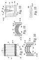
- Fig. 10 illustrates a highly preferred form of the fins 26, 50 utilized in the invention.
- the fins 26, 50 in this embodiment are arcuate as illustrated in Fig. 10 and include conventional louvers 80 along with spacing legs 82.
- the fin slots 34 (not shown) in Fig. 10 are free of flanges and abut the side walls 32 of the tubes 24, 56.
- the edges 84 will form a good bond with the flat sides 32 of the tubes 24, 56 when the aforementioned process or a conventional brazing process is employed.
- the fins 26, 50 are arcuate, provides a certain springiness or resilience to cause the edges 84 to be urged against the side walls 32.
- the absence of flanges on the edges 84 increases the air side free flow area to contribute to an improved air side heat transfer coefficient.
- Fig. 11 shows a somewhat less preferred embodiment of a fin 26, 50 that may be used in the invention.
- extremely small flanges 88 border the slots 34 in the fins and abut the flat sides 32 of the tubes 24, 56.
- the fins 26, 50 are arcuate.
- the importance of this feature is that the arcuate fins increase the air side surface without increasing fin height, i.e., the same number of the tubes 24, 56 may be fitted into a given frontal area even while the air side surface area is increased through the use of the curved fins. Consequently, the increase in area improves heat transfer on the air side while nothing is lost on the second fluid side because the same number of tubes 24, 56 may be employed.
- the length of the louvers is also increased, thereby increasing turbulence and heat transfer.
- the air side performance of the embodiment of Fig. 10 is slightly greater than that of the embodiment of Fig. 11 and considerably better than that of tubes having conventionally sized flanges for the reason that such flanges reduce the available air side free flow area through the heat exchanger.
- Fig. 12 shows another sort of flattened tube that may be employed in the invention.
- the tube is a tear-drop shaped tube 90 having multiple ports 92.
- the slots 94 in the fins 26, 50 are such as to snugly receive the tube 90, i.e., the slots 94 as they have a depth somewhat less than the major dimension of the tube 90 and area shaped like the cross-section of the tube 90.
- the width of the slot 94 can be made the same or again, just slightly smaller, than the minor dimension of the tube 90.
- one or more elongated stiffening ribs 100 extending the length of each of the fins 26, 50 can be employed.
- the stiffening rib is illustrated in both Figs. 12 and 13. In the case of the embodiment of Figs. 4 and 5, the stiffening rib would be located in the center of the fin, between the two rows of slots.
- the ribs 100 enhance condensate drainage when the heat exchanger is used as an evaporator.
- the tubes in one row may be staggered with respect to the tubes in one or more other rows.
- Fig. 14 the same illustrates test results for various fin constructions, including the fin constructions illustrated in Figs. 10 and 11.
- Standard air face velocity is plotted against a) heat flux for entering temperature difference in btu's per square foot per degree Fahrenheit and b) against air side pressure drop in inches of water.
- the curved fins of the invention compare favorably with conventional serpentine fins illustrating that the bonding problems incurred in plate fin heat exchangers are solved by the invention.
- heat exchange performance for fins made according to the invention possess a significant advantage.
- the fin of Fig. 10 shows an advantage over the fin of Fig. 11 both in terms of heat transfer and in terms of providing a lesser air side pressure drop.
- the invention provides a heat exchanger that eliminates round tubes which provide a high drag, i.e., increase air side pressure drop and eliminates mechanical bonds typically found in such heat exchangers. Furthermore, the invention allows the use of relatively small fin heights to avoid a loss of efficiency that occurs with large fin heights. While the heat exchanger of the invention is suited for many different applications, it is particularly used with advantage as an evaporator in that the use of vertical plate fins with stiffening ribs and gaps between the tubes provide for excellent drainage of condensation that conventionally occurs in evaporators used in refrigeration or air conditioning systems.
- the fins 26 on the one hand and 50 on the other may be made with the same die simply by repeating the stamping operation on both sides of a wider fin.
- the unique advantage provided by allowing the rounded edges 40 of the tubes to extend slightly past the edges 36, 52, 54 of the fins permits brazing of the components without the use of brazing fixtures designed to locate the fins in a common plane.
- curved fins increases the air side surface area without necessitating an increase in fin height and provides an additional advantage of inherent resilience causing the edges of the slots in the fins to tightly embrace the side walls 32 of the tubes to further assure a good bond during brazing.
Landscapes
- Engineering & Computer Science (AREA)
- Physics & Mathematics (AREA)
- Mechanical Engineering (AREA)
- Thermal Sciences (AREA)
- General Engineering & Computer Science (AREA)
- Geometry (AREA)
- Heat-Exchange Devices With Radiators And Conduit Assemblies (AREA)
- Details Of Heat-Exchange And Heat-Transfer (AREA)
Abstract
Description
Claims (30)
- A method of fabricating a heat exchanger comprising:a) providing a plurality of generally parallel tube runs of a flattened heat exchange tube having a major dimension and a minor dimension;b) providing a plurality of plate fins, each having a plurality of tube slots approximately equal to the number of tube runs, each slot opening to an edge of the associated fin and havingi) a shape corresponding to the cross-sectioned shape a tube run to be received in the slot,ii) a depth less than the major dimension of the tube run to be received in the slot, andiii) a width approximately equal to or slightly less than the minor dimension of the tube run to be received in the slot;c) fitting the tube runs snugly into corresponding slots in each of the fins such that an edge of each tube run extends a distance out of the slots in which it is received;d) locating the assembly resulting from step c) on a supporting surface with said tube run edges in contact with said supporting surface and with said plate fins extending above said tube runs; ande) subjecting said assembly to an elevated temperature sufficient to braze said fin to said tube runs while said assembly is on said supporting surface and in the absence of brazing fixtures holding said fins and said tube runs in assembled relation.
- The method of claim 1 wherein said tube runs are defined by straight sections of a serpentine tube.
- The method of claim 1 wherein said tube runs are each defined by a straight piece of tubing.
- The method of claim 1 wherein the cross-section of said tube runs is tear- drop shaped.
- The method of claim 1 wherein the cross-section of said tube runs is oval-shaped.
- The method of claim 1 wherein said fins are curved at locations between said slots.
- The method of claim 1 wherein said fins and said tube runs are formed of aluminum and/or alloys thereof.
- A method of fabricating an aluminum and/or aluminum alloy heat exchanger comprising the steps of:a) assembling a plurality of plate fins having open ended slots to a plurality of tube runs having the same cross-section shape as the slots such that an edge of each tube run extends a short distance out of the slots in which it is received;b) locating the assemblage resulting from step a) on a supporting surface with said tube run edges contacting said supporting surface and said fins above and out of contact with said supporting surface;c) locating an aluminum braze alloy at the interfaces of said tube runs and said fins; andd) subjecting the assembly resulting from the preceding steps to aluminum brazing temperatures in the absence of brazing fixtures holding said tube runs and said fins in assembled relation for a time sufficient to allow said fins to settle under gravitational forces onto said tube runs.
- The method of claim 8 wherein step c) is performed by cladding one or both of said fins and said tube runs with said aluminum braze alloy prior to the performance of step a).
- The method of claim 8 wherein said tube runs are of flattened tubing having a major dimension and a minor dimension and said slots have a depth somewhat less than said major dimension.
- The method of claim 8 including the step of providing the fins with curved sections between said slots.
- A method of fabrication of a heat exchanger comprising the steps of:a) assembling a plurality of plate fins having open ended slots to a plurality of tube runs having the same cross-section shape as the slots such that an edge of each tube run extends a short distance out of the slots in which it is received;b) locating the assemblage resulting from step a) on a supporting surface with said tube run edges contacting said supporting surface and said fins above and out of contact with said supporting surface; andc) subjecting the assembly resulting from the preceding steps to brazing temperature in the absence of brazing fixtures holding said tube runs and said fins in assembled relation for a time sufficient to allow said fins to settle under gravitational forces onto said tube runs.
- An aluminum heat exchanger, comprising:first and second headers;at least one flattened tube extending between and in fluid communication with said headers and defining a plurality of generally parallel tube runs in spaced relation to one another;each said tube runs having opposite edges defining a tube major dimension and interconnecting side walls defining a tube minor dimension and a plurality of interior ports;a plurality of plate fins arranged in a stack and each having a plurality of open ended tube run receiving slots, one for each tube run, each slot having a shape generally that of the cross-section of the tube run to be received therein, a width equal to or just less than the minor dimension of the corresponding tube run and a depth somewhat less than the major dimension of the corresponding tube run;each said tube run being nested within corresponding slots in said fins with one of said edges of each tube run located outwardly of the corresponding fin; andsaid headers, said tube runs and said fins comprising a brazed assembly.
- The heat exchanger of claim 13 wherein said tube runs are defined by individual tubes.
- The heat exchanger of claim 13 wherein said tube runs are defined by at least one serpentine tube.
- The heat exchanger of claim 13 wherein said slots are at least partially bounded by flanges brazed to said tube runs.
- The heat exchanger of claim 13 wherein said slots have flange free edges brazed to said tube runs.
- The heat exchanger of claim 13 wherein said fins are curved at locations between said slots.
- The heat exchanger of claim 13 wherein said plate fins are elongated and said slots open to one elongated edge thereof, the other elongated edge being uninterrupted by said slots.
- The heat exchanger of claim 19 including a stiffening bead between said other elongated edge and said slots.
- The heat exchanger of claim 18 wherein said plate fins are elongated and said slots open to both elongated edges thereof.
- The heat exchanger of claim 21 wherein the slots opening to one of said elongated edges are aligned with the slots opening to the other of said elongated edges.
- The heat exchanger of claim 21 including an elongated uninterrupted band extending in the direction of elongation of said plate fins located between the slots opening to said one elongated edge and the slots opening to said other elongated edge.
- The heat exchanger of claim 21 wherein said tube runs are defined by the legs of U-shaped tubes, one of said legs of each U-shaped tube being disposed in a slot opening to one elongated edge of said plate fin and the other leg being disposed in a slot opening to the other elongated edge.
- The heat exchanger of claim 24 wherein the slots opening to opposite ones of said elongated edges are aligned and the legs of each said U-shaped tube are located in aligned ones of said slots.
- The heat exchanger of claim 25 wherein each of said legs of each of said U-shaped tubes includes an angled twist of an angle up to and including 90°immediately adjacent the bight of the corresponding U-shaped tube.
- The heat exchanger of claim 13 wherein said parallel tube runs are defined by a plurality of U-shaped tubes, each having two parallel legs connected by a bight and there are two sets of said plate fins, one set disposed on corresponding first ones of the legs and the other set disposed on corresponding others of the legs.
- The heat exchanger of claim 27 wherein each of said legs of each of said U-shaped tubes includes a 90° twist immediately adjacent the bight of the corresponding U-shaped tube.
- A heat exchanger core comprising:a plurality of generally parallel tube runs formed of flattened, multi-port tubing; anda plurality of plate fins in a stacked relation and having spaced openings sufficient to receive said tube runs;said tube runs being disposed in said openings and having a major dimension brazed to the plate fins about said openings;the parts of said plate fins between the openings being arcuate in a direction generally transverse to said major dimension to thereby increase the surface area of the fins between the openings without the need to increase the spacing between adjacent openings.
- The heat exchanger of claim 29 wherein said openings are slots extending into the fins from one edge thereof.
Priority Applications (1)
| Application Number | Priority Date | Filing Date | Title |
|---|---|---|---|
| EP06011075A EP1691160A1 (en) | 2001-02-07 | 2002-02-01 | Heat exchanger |
Applications Claiming Priority (2)
| Application Number | Priority Date | Filing Date | Title |
|---|---|---|---|
| US09/778,310 US6964296B2 (en) | 2001-02-07 | 2001-02-07 | Heat exchanger |
| US778310 | 2001-02-07 |
Related Child Applications (1)
| Application Number | Title | Priority Date | Filing Date |
|---|---|---|---|
| EP06011075A Division EP1691160A1 (en) | 2001-02-07 | 2002-02-01 | Heat exchanger |
Publications (3)
| Publication Number | Publication Date |
|---|---|
| EP1231448A2 true EP1231448A2 (en) | 2002-08-14 |
| EP1231448A3 EP1231448A3 (en) | 2004-02-11 |
| EP1231448B1 EP1231448B1 (en) | 2007-04-18 |
Family
ID=25112917
Family Applications (2)
| Application Number | Title | Priority Date | Filing Date |
|---|---|---|---|
| EP06011075A Withdrawn EP1691160A1 (en) | 2001-02-07 | 2002-02-01 | Heat exchanger |
| EP02001951A Expired - Lifetime EP1231448B1 (en) | 2001-02-07 | 2002-02-01 | Heat exchanger |
Family Applications Before (1)
| Application Number | Title | Priority Date | Filing Date |
|---|---|---|---|
| EP06011075A Withdrawn EP1691160A1 (en) | 2001-02-07 | 2002-02-01 | Heat exchanger |
Country Status (13)
| Country | Link |
|---|---|
| US (2) | US6964296B2 (en) |
| EP (2) | EP1691160A1 (en) |
| JP (1) | JP4050910B2 (en) |
| KR (1) | KR20020065840A (en) |
| CN (1) | CN1280602C (en) |
| AR (2) | AR035737A1 (en) |
| AT (1) | ATE360183T1 (en) |
| AU (1) | AU783870B2 (en) |
| BR (1) | BR0200330A (en) |
| CA (1) | CA2368871A1 (en) |
| DE (1) | DE60219538T2 (en) |
| MX (1) | MXPA02001239A (en) |
| TW (1) | TW522215B (en) |
Cited By (9)
| Publication number | Priority date | Publication date | Assignee | Title |
|---|---|---|---|---|
| WO2003048670A1 (en) * | 2001-11-30 | 2003-06-12 | Modine Manufacturing Company | Heat exchanger for providing supercritical cooling of a working fluid in a transcritical cooling cycle |
| WO2007104580A3 (en) * | 2006-03-16 | 2008-04-17 | Behr Gmbh & Co Kg | Heat exchanger for a motor vehicle |
| FR2917819A1 (en) * | 2007-06-22 | 2008-12-26 | Valeo Systemes Thermiques | HEAT EXCHANGE MODULE FOR TWO HEAT EXCHANGE CIRCUITS |
| WO2014206441A1 (en) * | 2013-06-24 | 2014-12-31 | Electrolux Appliances Aktiebolag | Heat pump laundry dryer |
| EP2447659A3 (en) * | 2010-10-28 | 2015-04-08 | Samsung Electronics Co., Ltd. | Heat exchanger and fin for the same |
| EP2930453A1 (en) * | 2014-04-08 | 2015-10-14 | Hangzhou Sanhua Research Institute Co., Ltd. | Heat exchanger assembly and use thereof |
| WO2016036732A1 (en) * | 2014-09-05 | 2016-03-10 | Carrier Corporation | Frost tolerant microchannel heat exchanger for heat pump and refrigeration applications |
| EP2378232A3 (en) * | 2010-04-13 | 2017-04-19 | Sanhua (Hangzhou) Micro Channel Heat Exchanger Co., Ltd. | Bent micro-channel heat exchanger |
| EP3591324B1 (en) * | 2018-07-04 | 2023-09-06 | Zhejiang Dunan Thermal Technology Co., Ltd. | Micro-channel heat exchanger |
Families Citing this family (114)
| Publication number | Priority date | Publication date | Assignee | Title |
|---|---|---|---|---|
| US8744384B2 (en) | 2000-07-20 | 2014-06-03 | Blackberry Limited | Tunable microwave devices with auto-adjusting matching circuit |
| US8064188B2 (en) * | 2000-07-20 | 2011-11-22 | Paratek Microwave, Inc. | Optimized thin film capacitors |
| JP3864916B2 (en) * | 2002-08-29 | 2007-01-10 | 株式会社デンソー | Heat exchanger |
| FR2847973B1 (en) * | 2002-11-29 | 2006-01-27 | Valeo Climatisation | THERMAL INERTIAL HEAT EXCHANGER FOR A HEAT PUMP CIRCUIT, IN PARTICULAR A MOTOR VEHICLE. |
| DE10321458A1 (en) * | 2003-05-13 | 2004-12-02 | Behr Gmbh & Co. Kg | Heat exchanger unit for motor vehicles |
| DE10359806A1 (en) * | 2003-12-19 | 2005-07-14 | Modine Manufacturing Co., Racine | Heat exchanger with flat tubes and flat heat exchanger tube |
| WO2006004137A1 (en) * | 2004-07-05 | 2006-01-12 | Showa Denko K.K. | Evaporator |
| JP4654021B2 (en) * | 2004-12-22 | 2011-03-16 | 本田技研工業株式会社 | Multi-tube heat exchange device and method for manufacturing the same |
| JP2006214702A (en) * | 2005-02-07 | 2006-08-17 | Denso Corp | HEAT EXCHANGER, HEAT EXCHANGER MANUFACTURING METHOD, AND HEAT EXCHANGER PLATE FIN |
| US20070012430A1 (en) * | 2005-07-18 | 2007-01-18 | Duke Brian E | Heat exchangers with corrugated heat exchange elements of improved strength |
| DE102005053924B4 (en) * | 2005-11-11 | 2016-03-31 | Modine Manufacturing Co. | Intercooler in plate construction |
| US9406444B2 (en) | 2005-11-14 | 2016-08-02 | Blackberry Limited | Thin film capacitors |
| US7711337B2 (en) | 2006-01-14 | 2010-05-04 | Paratek Microwave, Inc. | Adaptive impedance matching module (AIMM) control architectures |
| US8325097B2 (en) | 2006-01-14 | 2012-12-04 | Research In Motion Rf, Inc. | Adaptively tunable antennas and method of operation therefore |
| US8125399B2 (en) | 2006-01-14 | 2012-02-28 | Paratek Microwave, Inc. | Adaptively tunable antennas incorporating an external probe to monitor radiated power |
| ES2284375B1 (en) * | 2006-02-15 | 2008-10-16 | Corporacion Capricornio Technologies, S.L. | HEAT EXCHANGER AND CLIMATE CONTROL THAT INCLUDES SUCH EXCHANGER. |
| CN100462159C (en) * | 2006-07-04 | 2009-02-18 | 陈世明 | Manufacturing method of direct group heat transfer cooling device |
| WO2008045111A1 (en) * | 2006-10-13 | 2008-04-17 | Carrier Corporation | Multi-channel heat exchanger with multi-stage expansion device |
| US8299867B2 (en) | 2006-11-08 | 2012-10-30 | Research In Motion Rf, Inc. | Adaptive impedance matching module |
| US7714676B2 (en) | 2006-11-08 | 2010-05-11 | Paratek Microwave, Inc. | Adaptive impedance matching apparatus, system and method |
| US7535312B2 (en) | 2006-11-08 | 2009-05-19 | Paratek Microwave, Inc. | Adaptive impedance matching apparatus, system and method with improved dynamic range |
| WO2008064219A1 (en) * | 2006-11-22 | 2008-05-29 | Johnson Controls Technology Company | Multichannel evaporator with flow mixing manifold |
| WO2008064251A2 (en) * | 2006-11-22 | 2008-05-29 | Johnson Controls Technology Company | Space-saving multichannel heat exchanger |
| WO2008064247A1 (en) * | 2006-11-22 | 2008-05-29 | Johnson Controls Technology Company | Multi-function multichannel heat exchanger |
| WO2008079132A1 (en) * | 2006-12-26 | 2008-07-03 | Carrier Corporation | Multi-channel heat exchanger with improved condensate drainage |
| US20090250201A1 (en) * | 2008-04-02 | 2009-10-08 | Grippe Frank M | Heat exchanger having a contoured insert and method of assembling the same |
| BRPI0807410A2 (en) * | 2007-01-23 | 2014-05-27 | Modine Mfg Co | Heat Exchanger and Method |
| US7921904B2 (en) * | 2007-01-23 | 2011-04-12 | Modine Manufacturing Company | Heat exchanger and method |
| US8424592B2 (en) * | 2007-01-23 | 2013-04-23 | Modine Manufacturing Company | Heat exchanger having convoluted fin end and method of assembling the same |
| US7917104B2 (en) | 2007-04-23 | 2011-03-29 | Paratek Microwave, Inc. | Techniques for improved adaptive impedance matching |
| US8213886B2 (en) | 2007-05-07 | 2012-07-03 | Paratek Microwave, Inc. | Hybrid techniques for antenna retuning utilizing transmit and receive power information |
| US20090025405A1 (en) * | 2007-07-27 | 2009-01-29 | Johnson Controls Technology Company | Economized Vapor Compression Circuit |
| US8166776B2 (en) * | 2007-07-27 | 2012-05-01 | Johnson Controls Technology Company | Multichannel heat exchanger |
| US7942020B2 (en) | 2007-07-27 | 2011-05-17 | Johnson Controls Technology Company | Multi-slab multichannel heat exchanger |
| EP2193315B1 (en) * | 2007-08-24 | 2011-10-12 | Johnson Controls Technology Company | A vapor compression system and method of controlling it |
| US8117864B2 (en) * | 2007-10-31 | 2012-02-21 | Illinois Tool Works Inc. | Compact, modularized air conditioning system that can be mounted upon an airplane ground support equipment cart |
| US8037714B2 (en) * | 2007-10-31 | 2011-10-18 | Illinois Tool Works Inc. | Adjustable air conditioning control system for a universal airplane ground support equipment cart |
| US8055388B2 (en) * | 2007-10-31 | 2011-11-08 | Illinois Tool Works Inc. | Maintenance and control system for ground support equipment |
| US8047555B2 (en) * | 2007-10-31 | 2011-11-01 | Illinois Tool Works Inc. | Airplane ground support equipment cart having extractable modules and a generator module that is seperable from power conversion and air conditioning modules |
| US7991363B2 (en) | 2007-11-14 | 2011-08-02 | Paratek Microwave, Inc. | Tuning matching circuits for transmitter and receiver bands as a function of transmitter metrics |
| US20090154091A1 (en) | 2007-12-17 | 2009-06-18 | Yatskov Alexander I | Cooling systems and heat exchangers for cooling computer components |
| WO2009078869A1 (en) * | 2007-12-18 | 2009-06-25 | Carrier Corporation | Heat exchanger for shedding water |
| US8170724B2 (en) | 2008-02-11 | 2012-05-01 | Cray Inc. | Systems and associated methods for controllably cooling computer components |
| US20100006276A1 (en) * | 2008-07-11 | 2010-01-14 | Johnson Controls Technology Company | Multichannel Heat Exchanger |
| US8072285B2 (en) * | 2008-09-24 | 2011-12-06 | Paratek Microwave, Inc. | Methods for tuning an adaptive impedance matching network with a look-up table |
| US20100115771A1 (en) * | 2008-11-10 | 2010-05-13 | Mark Johnson | Heat exchanger, heat exchanger tubes and method |
| US8541721B2 (en) | 2008-12-01 | 2013-09-24 | Daniel Moskal | Wake generating solid elements for joule heating or infrared heating |
| US9874403B2 (en) * | 2009-02-27 | 2018-01-23 | Electrolux Home Products, Inc. | Evaporator fins in contact with end bracket |
| JP4503682B1 (en) * | 2009-04-22 | 2010-07-14 | シャープ株式会社 | Heat exchanger and air conditioner equipped with the same |
| US20110030932A1 (en) * | 2009-08-07 | 2011-02-10 | Johnson Controls Technology Company | Multichannel heat exchanger fins |
| US8472888B2 (en) | 2009-08-25 | 2013-06-25 | Research In Motion Rf, Inc. | Method and apparatus for calibrating a communication device |
| US9026062B2 (en) | 2009-10-10 | 2015-05-05 | Blackberry Limited | Method and apparatus for managing operations of a communication device |
| US8439104B2 (en) * | 2009-10-16 | 2013-05-14 | Johnson Controls Technology Company | Multichannel heat exchanger with improved flow distribution |
| US8464782B2 (en) * | 2009-10-20 | 2013-06-18 | Delphi Technologies, Inc. | Manifold fluid communication plate |
| US8803631B2 (en) | 2010-03-22 | 2014-08-12 | Blackberry Limited | Method and apparatus for adapting a variable impedance network |
| US8472181B2 (en) | 2010-04-20 | 2013-06-25 | Cray Inc. | Computer cabinets having progressive air velocity cooling systems and associated methods of manufacture and use |
| CA2797074C (en) | 2010-04-20 | 2018-08-14 | Research In Motion Rf, Inc. | Method and apparatus for managing interference in a communication device |
| JP5312413B2 (en) * | 2010-08-09 | 2013-10-09 | 三菱電機株式会社 | Finned tube heat exchanger and refrigeration cycle apparatus using the same |
| KR20120044848A (en) * | 2010-10-28 | 2012-05-08 | 삼성전자주식회사 | Heat exchanger and micro-channel tube for the same |
| US9379454B2 (en) | 2010-11-08 | 2016-06-28 | Blackberry Limited | Method and apparatus for tuning antennas in a communication device |
| CN103270386A (en) | 2010-11-22 | 2013-08-28 | 开利公司 | Multi-tube bundle flattened tube-fin heat exchanger |
| JP5397489B2 (en) * | 2011-01-21 | 2014-01-22 | ダイキン工業株式会社 | Heat exchanger and air conditioner |
| EP2657637A4 (en) * | 2011-01-21 | 2014-07-09 | Daikin Ind Ltd | HEAT EXCHANGER AND AIR CONDITIONER |
| US20130299153A1 (en) * | 2011-01-21 | 2013-11-14 | Daikin Industries, Ltd. | Heat exchanger and air conditioner |
| JP5177308B2 (en) * | 2011-01-21 | 2013-04-03 | ダイキン工業株式会社 | Heat exchanger and air conditioner |
| US8712340B2 (en) | 2011-02-18 | 2014-04-29 | Blackberry Limited | Method and apparatus for radio antenna frequency tuning |
| US8655286B2 (en) | 2011-02-25 | 2014-02-18 | Blackberry Limited | Method and apparatus for tuning a communication device |
| US8626083B2 (en) | 2011-05-16 | 2014-01-07 | Blackberry Limited | Method and apparatus for tuning a communication device |
| US8594584B2 (en) | 2011-05-16 | 2013-11-26 | Blackberry Limited | Method and apparatus for tuning a communication device |
| CN102886667B (en) * | 2011-07-22 | 2015-05-06 | 常州市西屋自动化有限公司 | Fin lateral assembly fixture of heat exchanger |
| CN102330719A (en) * | 2011-07-29 | 2012-01-25 | 烟台富耐克散热器有限公司 | Tube-strip type oil radiator |
| WO2013022826A1 (en) | 2011-08-05 | 2013-02-14 | Research In Motion Rf, Inc. | Method and apparatus for band tuning in a communication device |
| JP5403029B2 (en) * | 2011-10-07 | 2014-01-29 | ダイキン工業株式会社 | Refrigeration equipment |
| EP3767219A1 (en) | 2011-10-19 | 2021-01-20 | Carrier Corporation | Flattened tube finned heat exchanger and fabrication method |
| US20140196874A1 (en) * | 2011-12-26 | 2014-07-17 | Mitsubishi Electric Corporation | Outdoor unit, air-conditioning apparatus, and method for manufacturing outdoor units |
| KR20130084178A (en) * | 2012-01-16 | 2013-07-24 | 삼성전자주식회사 | Header and heat exchanger having the same |
| ES2662491T3 (en) | 2012-02-02 | 2018-04-06 | Carrier Corporation | Method for manufacturing a heat exchanger with flaps and flattened tubes |
| US8948889B2 (en) | 2012-06-01 | 2015-02-03 | Blackberry Limited | Methods and apparatus for tuning circuit components of a communication device |
| US9853363B2 (en) | 2012-07-06 | 2017-12-26 | Blackberry Limited | Methods and apparatus to control mutual coupling between antennas |
| US9246223B2 (en) | 2012-07-17 | 2016-01-26 | Blackberry Limited | Antenna tuning for multiband operation |
| US9413066B2 (en) | 2012-07-19 | 2016-08-09 | Blackberry Limited | Method and apparatus for beam forming and antenna tuning in a communication device |
| US9350405B2 (en) | 2012-07-19 | 2016-05-24 | Blackberry Limited | Method and apparatus for antenna tuning and power consumption management in a communication device |
| US9362891B2 (en) | 2012-07-26 | 2016-06-07 | Blackberry Limited | Methods and apparatus for tuning a communication device |
| US10404295B2 (en) | 2012-12-21 | 2019-09-03 | Blackberry Limited | Method and apparatus for adjusting the timing of radio antenna tuning |
| US9374113B2 (en) | 2012-12-21 | 2016-06-21 | Blackberry Limited | Method and apparatus for adjusting the timing of radio antenna tuning |
| WO2014116351A1 (en) | 2013-01-28 | 2014-07-31 | Carrier Corporation | Multiple tube bank heat exchange unit with manifold assembly |
| US10508862B2 (en) | 2013-03-15 | 2019-12-17 | Carrier Corporation | Heat exchanger for air-cooled chiller |
| JP5900440B2 (en) * | 2013-09-11 | 2016-04-06 | ダイキン工業株式会社 | Manufacturing method of heat exchanger and heat exchanger |
| WO2015037235A1 (en) * | 2013-09-11 | 2015-03-19 | ダイキン工業株式会社 | Heat exchanger, air conditioner, and heat exchanger manufacturing method |
| WO2015040746A1 (en) * | 2013-09-20 | 2015-03-26 | 三菱電機株式会社 | Heat exchanger, air conditioner device using said heat exchanger, and method for producing said heat exchanger |
| ES2877092T3 (en) | 2013-11-25 | 2021-11-16 | Carrier Corp | Double duty microchannel heat exchanger |
| DE102014206612A1 (en) * | 2014-04-04 | 2015-10-29 | Mahle International Gmbh | heat exchangers |
| CN104154778B (en) * | 2014-08-13 | 2017-02-08 | 丹佛斯微通道换热器(嘉兴)有限公司 | Heat exchanger and method for manufacturing heat exchanger |
| JP6661880B2 (en) * | 2014-09-01 | 2020-03-11 | 株式会社富士通ゼネラル | Air conditioner |
| JP6582373B2 (en) * | 2014-09-01 | 2019-10-02 | 株式会社富士通ゼネラル | Heat exchanger |
| WO2016036726A1 (en) | 2014-09-05 | 2016-03-10 | Carrier Corporation | Multiport extruded heat exchanger |
| CN107110568A (en) * | 2014-11-17 | 2017-08-29 | 开利公司 | The collapsible micro-channel heat exchanger of many plates of multi-path |
| US9438319B2 (en) | 2014-12-16 | 2016-09-06 | Blackberry Limited | Method and apparatus for antenna selection |
| JP6641721B2 (en) * | 2015-04-27 | 2020-02-05 | ダイキン工業株式会社 | Heat exchangers and air conditioners |
| CN106546119A (en) * | 2015-09-21 | 2017-03-29 | 杭州三花微通道换热器有限公司 | Fin and the heat exchanger with it |
| CN107218822B (en) * | 2016-03-21 | 2019-04-19 | 丹佛斯微通道换热器(嘉兴)有限公司 | heat exchanger and air conditioning system |
| JP6380449B2 (en) * | 2016-04-07 | 2018-08-29 | ダイキン工業株式会社 | Indoor heat exchanger |
| CN111527368B (en) * | 2018-01-19 | 2022-05-13 | 株式会社电装 | Heat exchanger |
| JP7092987B2 (en) * | 2018-01-22 | 2022-06-29 | ダイキン工業株式会社 | Indoor heat exchanger and air conditioner |
| US11022382B2 (en) * | 2018-03-08 | 2021-06-01 | Johnson Controls Technology Company | System and method for heat exchanger of an HVAC and R system |
| KR102020961B1 (en) * | 2018-10-08 | 2019-09-11 | 삼익기전 주식회사 | A heat exchange assembly for an heat dissipating electronic device having improved sealing performance and thermal efficiency |
| CN109396290B (en) * | 2018-11-29 | 2024-09-27 | 南宁市安和机械设备有限公司 | Fin inserting machine with flaring flattening function |
| US11047631B2 (en) * | 2019-02-20 | 2021-06-29 | Caterpillar Inc. | Bumper clip for tube type heat exchangers |
| CN109827335B (en) * | 2019-03-21 | 2023-12-05 | 西安交通大学 | A fully modular flue extruded aluminum condensing heat exchanger |
| CN111895839B (en) * | 2019-05-05 | 2021-09-21 | 浙江三花智能控制股份有限公司 | Micro-channel flat tube and micro-channel heat exchanger |
| JP7788862B2 (en) * | 2022-01-12 | 2025-12-19 | 三菱電機株式会社 | Method for manufacturing a heat exchanger and method for manufacturing an air conditioner |
| CN115194032B (en) * | 2022-07-14 | 2025-06-27 | 武汉宏海科技股份有限公司 | Serial air conditioner radiator tube expansion machine and its use method |
| EP4317899A1 (en) * | 2022-08-04 | 2024-02-07 | Valeo Systemes Thermiques | A tube for a heat exchanger |
| MX2024013541A (en) * | 2023-11-23 | 2025-06-02 | Danfoss As | Heat exchanger, air conditioning system and heat exchange system |
Family Cites Families (71)
| Publication number | Priority date | Publication date | Assignee | Title |
|---|---|---|---|---|
| US1913175A (en) * | 1930-04-04 | 1933-06-06 | Frigidaire Corp | Method of making refrigerating apparatus |
| US1993872A (en) * | 1932-04-06 | 1935-03-12 | Gen Motors Corp | Radiator core |
| US1950500A (en) * | 1932-04-19 | 1934-03-13 | Loprich | Radiator fin |
| US2011853A (en) * | 1932-07-25 | 1935-08-20 | Gen Motors Corp | Radiator core |
| US1998663A (en) * | 1934-03-23 | 1935-04-23 | Gen Motors Corp | Radiator core |
| US2271538A (en) * | 1938-04-25 | 1942-02-03 | Hoover Co | Heat exchange and method of making the same |
| US2427336A (en) | 1945-04-25 | 1947-09-16 | Peerless Of America | Heat transfer unit |
| DE852249C (en) | 1949-09-14 | 1952-10-13 | Adolf Dipl-Ing Schild | Finned tube block |
| US3167046A (en) * | 1956-01-24 | 1965-01-26 | Modine Mfg Co | Method of forming a sheet metal fin strip element for heat exchange structures |
| US3149667A (en) * | 1962-09-24 | 1964-09-22 | Young Radiator Co | Core-unit for vehicular-radiator-type heat exchanger and protective shields therefor |
| CH435627A (en) * | 1966-03-30 | 1967-05-15 | Zehnder Ag Geb | Method of manufacturing a central heating radiator |
| CH519151A (en) * | 1969-06-13 | 1972-02-15 | Schoell Guenter | Finned tube, process for its manufacture, and apparatus for carrying out the process |
| US3771595A (en) * | 1971-09-22 | 1973-11-13 | Modine Mfg Co | Heat exchange device |
| US3757856A (en) * | 1971-10-15 | 1973-09-11 | Union Carbide Corp | Primary surface heat exchanger and manufacture thereof |
| US4586563A (en) * | 1979-06-20 | 1986-05-06 | Dubrovsky Evgeny V | Tube-and-plate heat exchanger |
| SU960522A2 (en) * | 1980-01-28 | 1982-09-23 | Предприятие П/Я А-1697 | Tube-and-plate type heat exchanger |
| US4492851A (en) * | 1980-12-29 | 1985-01-08 | Brazeway, Inc. | Swap action arrangement mounting an electric defroster heater to a finned refrigeration unit |
| US4465129A (en) * | 1982-04-19 | 1984-08-14 | Blackstone Corporation | Heat exchanger core assembly construction and methods of making the same |
| US4601089A (en) * | 1983-10-21 | 1986-07-22 | Pal Gal | Process for the manufacture of heat-exchanger elements of strip-finned heat-exchangers |
| US5190100B1 (en) * | 1986-07-29 | 1994-08-30 | Showa Aluminum Corp | Condenser for use in a car cooling system |
| EP0255313B1 (en) * | 1986-07-29 | 1990-10-31 | Showa Aluminum Kabushiki Kaisha | Condenser |
| US5246064A (en) * | 1986-07-29 | 1993-09-21 | Showa Aluminum Corporation | Condenser for use in a car cooling system |
| US5482112A (en) * | 1986-07-29 | 1996-01-09 | Showa Aluminum Kabushiki Kaisha | Condenser |
| US5458190A (en) * | 1986-07-29 | 1995-10-17 | Showa Aluminum Corporation | Condenser |
| US4860822A (en) * | 1987-12-02 | 1989-08-29 | Carrier Corporation | Lanced sine-wave heat exchanger |
| JPH0645155Y2 (en) * | 1988-10-24 | 1994-11-16 | サンデン株式会社 | Heat exchanger |
| JPH02169177A (en) * | 1988-12-16 | 1990-06-29 | Matsushita Refrig Co Ltd | Heat exchanger manufacturing method |
| US5048602A (en) * | 1989-05-22 | 1991-09-17 | Showa Aluminum Kabushiki Kaisha | Heat exchangers |
| US5529116A (en) * | 1989-08-23 | 1996-06-25 | Showa Aluminum Corporation | Duplex heat exchanger |
| JPH0399193A (en) | 1989-09-08 | 1991-04-24 | Toshiba Corp | Heat exchanger |
| JP2786702B2 (en) * | 1989-12-07 | 1998-08-13 | 昭和アルミニウム株式会社 | Double integrated heat exchanger |
| JPH0717965Y2 (en) * | 1990-02-22 | 1995-04-26 | サンデン株式会社 | Heat exchanger |
| JP2513332Y2 (en) * | 1990-02-22 | 1996-10-02 | サンデン株式会社 | Heat exchanger |
| JPH0599581A (en) * | 1991-08-08 | 1993-04-20 | Nippon Light Metal Co Ltd | Heat exchanger and manufacturing method thereof |
| JP3064055B2 (en) * | 1991-08-29 | 2000-07-12 | 昭和アルミニウム株式会社 | Heat exchanger manufacturing method |
| US5236045A (en) * | 1992-04-03 | 1993-08-17 | L & M Radiator, Inc. | Heat exchanger tube |
| JPH0650688A (en) * | 1992-07-29 | 1994-02-25 | Toshiba Corp | Heat exchanger |
| US5467816A (en) * | 1993-02-08 | 1995-11-21 | Larinoff; Michael W. | Finned tubes for air-cooled steam condensers |
| KR950009505B1 (en) * | 1993-03-05 | 1995-08-23 | 주식회사두원공조 | Method manufacturing heat-exchanger used in motors |
| US5329988A (en) * | 1993-05-28 | 1994-07-19 | The Allen Group, Inc. | Heat exchanger |
| US5289874A (en) * | 1993-06-28 | 1994-03-01 | General Motors Corporation | Heat exchanger with laterally displaced louvered fin sections |
| CN1051151C (en) * | 1993-07-21 | 2000-04-05 | 巴伯库克日立株式会社 | Heat exchanger using finned tubes |
| JP3305460B2 (en) * | 1993-11-24 | 2002-07-22 | 昭和電工株式会社 | Heat exchanger |
| JPH08136183A (en) * | 1994-11-04 | 1996-05-31 | Zexel Corp | Laminated type heat exchanger |
| US5509199A (en) * | 1995-01-17 | 1996-04-23 | General Motors Corporation | Method of making a dual radiator and condenser assembly |
| US5501270A (en) * | 1995-03-09 | 1996-03-26 | Ford Motor Company | Plate fin heat exchanger |
| JPH0979766A (en) | 1995-09-12 | 1997-03-28 | Nippon Light Metal Co Ltd | Heat exchanger and manufacturing method thereof |
| US5992514A (en) * | 1995-11-13 | 1999-11-30 | Denso Corporation | Heat exchanger having several exchanging portions |
| KR0165067B1 (en) * | 1996-04-09 | 1999-01-15 | 구자홍 | 2-row flat tube heat exchanger |
| JPH09280762A (en) | 1996-04-15 | 1997-10-31 | Nippon Light Metal Co Ltd | Heat exchanger and method of manufacturing the same |
| US6016864A (en) * | 1996-04-19 | 2000-01-25 | Heatcraft Inc. | Heat exchanger with relatively flat fluid conduits |
| US5771964A (en) * | 1996-04-19 | 1998-06-30 | Heatcraft Inc. | Heat exchanger with relatively flat fluid conduits |
| JPH09310993A (en) | 1996-05-22 | 1997-12-02 | Nippon Light Metal Co Ltd | Heat exchanger manufacturing method and heat exchanger |
| JPH1062084A (en) | 1996-08-22 | 1998-03-06 | Nippon Light Metal Co Ltd | Heat exchanger manufacturing method and heat exchanger |
| JPH1089870A (en) | 1996-09-18 | 1998-04-10 | Nippon Light Metal Co Ltd | Heat exchanger manufacturing method and heat exchanger |
| JP3508465B2 (en) * | 1997-05-09 | 2004-03-22 | 株式会社デンソー | Heat exchanger |
| AU5121598A (en) * | 1997-05-12 | 1998-12-08 | Norsk Hydro Asa | Heat exchanger |
| JPH10339593A (en) | 1997-06-05 | 1998-12-22 | Nippon Light Metal Co Ltd | Heat exchanger and manufacture thereof |
| JPH10339587A (en) | 1997-06-10 | 1998-12-22 | Nippon Light Metal Co Ltd | Heat exchanger |
| JPH11108576A (en) | 1997-10-02 | 1999-04-23 | Nippon Light Metal Co Ltd | Heat exchanger |
| JPH11226685A (en) * | 1998-02-16 | 1999-08-24 | Denso Corp | Method of manufacturing heat exchanger and header tank |
| JP4062775B2 (en) * | 1998-02-24 | 2008-03-19 | 株式会社デンソー | Double heat exchanger |
| JPH11294984A (en) * | 1998-04-09 | 1999-10-29 | Zexel:Kk | Juxtaposed integrated heat exchanger |
| KR100297189B1 (en) * | 1998-11-20 | 2001-11-26 | 황해웅 | High efficiency modular OEL heat exchanger with heat transfer promoting effect |
| JP3879296B2 (en) * | 1999-01-19 | 2007-02-07 | 株式会社デンソー | Heat exchanger |
| JP4117429B2 (en) * | 1999-02-01 | 2008-07-16 | 株式会社デンソー | Heat exchanger fins |
| US6155339A (en) * | 1999-06-18 | 2000-12-05 | Grapengater; Richard B. | Obround header for a heat exchanger |
| JP4482991B2 (en) * | 1999-12-14 | 2010-06-16 | 株式会社デンソー | Double heat exchanger |
| FR2804501B1 (en) * | 2000-01-28 | 2002-04-12 | Valeo Thermique Moteur Sa | HEAT EXCHANGE MODULE, IN PARTICULAR FOR A MOTOR VEHICLE |
| JP2002139282A (en) * | 2000-10-31 | 2002-05-17 | Mitsubishi Electric Corp | Heat exchanger, refrigerating air conditioner and manufacturing method of heat exchanger |
| US6745827B2 (en) * | 2001-09-29 | 2004-06-08 | Halla Climate Control Corporation | Heat exchanger |
-
2001
- 2001-02-07 US US09/778,310 patent/US6964296B2/en not_active Expired - Fee Related
-
2002
- 2002-01-16 TW TW091100586A patent/TW522215B/en not_active IP Right Cessation
- 2002-01-17 AU AU10222/02A patent/AU783870B2/en not_active Ceased
- 2002-01-21 AR ARP020100200A patent/AR035737A1/en unknown
- 2002-01-22 CA CA002368871A patent/CA2368871A1/en not_active Abandoned
- 2002-01-29 BR BR0200330-9A patent/BR0200330A/en not_active Application Discontinuation
- 2002-01-29 KR KR1020020005016A patent/KR20020065840A/en not_active Ceased
- 2002-02-01 DE DE60219538T patent/DE60219538T2/en not_active Expired - Fee Related
- 2002-02-01 EP EP06011075A patent/EP1691160A1/en not_active Withdrawn
- 2002-02-01 AT AT02001951T patent/ATE360183T1/en not_active IP Right Cessation
- 2002-02-01 EP EP02001951A patent/EP1231448B1/en not_active Expired - Lifetime
- 2002-02-04 MX MXPA02001239A patent/MXPA02001239A/en active IP Right Grant
- 2002-02-06 CN CNB021034656A patent/CN1280602C/en not_active Expired - Fee Related
- 2002-02-06 JP JP2002029180A patent/JP4050910B2/en not_active Expired - Fee Related
-
2004
- 2004-01-20 US US10/760,597 patent/US7032313B2/en not_active Expired - Fee Related
- 2004-05-07 AR ARP040101562A patent/AR044266A2/en unknown
Cited By (13)
| Publication number | Priority date | Publication date | Assignee | Title |
|---|---|---|---|---|
| WO2003048670A1 (en) * | 2001-11-30 | 2003-06-12 | Modine Manufacturing Company | Heat exchanger for providing supercritical cooling of a working fluid in a transcritical cooling cycle |
| WO2007104580A3 (en) * | 2006-03-16 | 2008-04-17 | Behr Gmbh & Co Kg | Heat exchanger for a motor vehicle |
| US8544454B2 (en) | 2006-03-16 | 2013-10-01 | Behr Gmbh & Co. Kg | Heat exchanger for a motor vehicle |
| FR2917819A1 (en) * | 2007-06-22 | 2008-12-26 | Valeo Systemes Thermiques | HEAT EXCHANGE MODULE FOR TWO HEAT EXCHANGE CIRCUITS |
| WO2009000581A1 (en) * | 2007-06-22 | 2008-12-31 | Valeo Systemes Thermiques | Heat exchange module for two heat exchange circuits |
| EP2378232A3 (en) * | 2010-04-13 | 2017-04-19 | Sanhua (Hangzhou) Micro Channel Heat Exchanger Co., Ltd. | Bent micro-channel heat exchanger |
| EP2447659A3 (en) * | 2010-10-28 | 2015-04-08 | Samsung Electronics Co., Ltd. | Heat exchanger and fin for the same |
| WO2014206441A1 (en) * | 2013-06-24 | 2014-12-31 | Electrolux Appliances Aktiebolag | Heat pump laundry dryer |
| AU2013396776B2 (en) * | 2013-06-24 | 2018-12-06 | Electrolux Appliances Aktiebolag | Heat pump laundry dryer |
| EP2930453A1 (en) * | 2014-04-08 | 2015-10-14 | Hangzhou Sanhua Research Institute Co., Ltd. | Heat exchanger assembly and use thereof |
| WO2016036732A1 (en) * | 2014-09-05 | 2016-03-10 | Carrier Corporation | Frost tolerant microchannel heat exchanger for heat pump and refrigeration applications |
| EP3591324B1 (en) * | 2018-07-04 | 2023-09-06 | Zhejiang Dunan Thermal Technology Co., Ltd. | Micro-channel heat exchanger |
| US11874066B2 (en) | 2018-07-04 | 2024-01-16 | Zhejiang Dunan Thermal Technology Co., Ltd. | Micro-channel heat exchanger |
Also Published As
| Publication number | Publication date |
|---|---|
| AU1022202A (en) | 2002-08-08 |
| DE60219538D1 (en) | 2007-05-31 |
| CN1280602C (en) | 2006-10-18 |
| EP1231448A3 (en) | 2004-02-11 |
| DE60219538T2 (en) | 2007-12-20 |
| JP4050910B2 (en) | 2008-02-20 |
| AU783870B2 (en) | 2005-12-15 |
| US7032313B2 (en) | 2006-04-25 |
| BR0200330A (en) | 2002-10-29 |
| US20040149424A1 (en) | 2004-08-05 |
| KR20020065840A (en) | 2002-08-14 |
| EP1691160A1 (en) | 2006-08-16 |
| MXPA02001239A (en) | 2002-09-19 |
| CN1369680A (en) | 2002-09-18 |
| ATE360183T1 (en) | 2007-05-15 |
| TW522215B (en) | 2003-03-01 |
| AR035737A1 (en) | 2004-07-07 |
| EP1231448B1 (en) | 2007-04-18 |
| JP2002318087A (en) | 2002-10-31 |
| US20020134537A1 (en) | 2002-09-26 |
| AR044266A2 (en) | 2005-09-07 |
| US6964296B2 (en) | 2005-11-15 |
| CA2368871A1 (en) | 2002-08-07 |
Similar Documents
| Publication | Publication Date | Title |
|---|---|---|
| US7032313B2 (en) | Method of fabricating a heat exchanger | |
| EP0360362B1 (en) | Condenser | |
| US4825941A (en) | Condenser for use in a car cooling system | |
| CA2023499C (en) | Duplex heat exchanger | |
| US5341870A (en) | Evaporator or evaporator/condenser | |
| US5722485A (en) | Louvered fin heat exchanger | |
| EP2810010B1 (en) | Multiple tube bank heat exchanger assembly and fabrication method | |
| US20060070726A1 (en) | Plate fin for heat exchanger and heat exchanger core | |
| JPH01193596A (en) | Plate fin for heat exchanger and plate fin tube type heat exchanger | |
| US9593889B2 (en) | Heat exchanger construction | |
| US5246064A (en) | Condenser for use in a car cooling system | |
| US5190100A (en) | Condenser for use in a car cooling system | |
| US3217798A (en) | Heat exchanger | |
| US20030131979A1 (en) | Oil cooler | |
| JP3870865B2 (en) | Heat exchanger | |
| CN100357697C (en) | Flat tube, and method of manufacturing heat exchanger using flat tube | |
| US20030102112A1 (en) | Flattened tube heat exchanger made from micro-channel tubing | |
| JPH0755380A (en) | Heat exchanger | |
| JPH1137683A (en) | Heat exchanger | |
| JPH0674669A (en) | Heat exchanger | |
| CA1326481C (en) | Condenser | |
| JPH06101982A (en) | Heat exchanger | |
| JPS633712B2 (en) | ||
| JPH05272845A (en) | Lamination type heat-exchanger |
Legal Events
| Date | Code | Title | Description |
|---|---|---|---|
| PUAI | Public reference made under article 153(3) epc to a published international application that has entered the european phase |
Free format text: ORIGINAL CODE: 0009012 |
|
| 17P | Request for examination filed |
Effective date: 20020201 |
|
| AK | Designated contracting states |
Kind code of ref document: A2 Designated state(s): AT BE CH CY DE DK ES FI FR GB GR IE IT LI LU MC NL PT SE TR |
|
| AX | Request for extension of the european patent |
Free format text: AL;LT;LV;MK;RO;SI |
|
| PUAL | Search report despatched |
Free format text: ORIGINAL CODE: 0009013 |
|
| AK | Designated contracting states |
Kind code of ref document: A3 Designated state(s): AT BE CH CY DE DK ES FI FR GB GR IE IT LI LU MC NL PT SE TR |
|
| AX | Request for extension of the european patent |
Extension state: AL LT LV MK RO SI |
|
| RIC1 | Information provided on ipc code assigned before grant |
Ipc: 7F 28F 1/32 A |
|
| AKX | Designation fees paid |
Designated state(s): AT DE ES FR GB IT |
|
| 17Q | First examination report despatched |
Effective date: 20041112 |
|
| GRAP | Despatch of communication of intention to grant a patent |
Free format text: ORIGINAL CODE: EPIDOSNIGR1 |
|
| GRAS | Grant fee paid |
Free format text: ORIGINAL CODE: EPIDOSNIGR3 |
|
| GRAA | (expected) grant |
Free format text: ORIGINAL CODE: 0009210 |
|
| AK | Designated contracting states |
Kind code of ref document: B1 Designated state(s): AT DE ES FR GB IT |
|
| REF | Corresponds to: |
Ref document number: 60219538 Country of ref document: DE Date of ref document: 20070531 Kind code of ref document: P |
|
| PG25 | Lapsed in a contracting state [announced via postgrant information from national office to epo] |
Ref country code: ES Free format text: LAPSE BECAUSE OF FAILURE TO SUBMIT A TRANSLATION OF THE DESCRIPTION OR TO PAY THE FEE WITHIN THE PRESCRIBED TIME-LIMIT Effective date: 20070729 |
|
| ET | Fr: translation filed | ||
| PG25 | Lapsed in a contracting state [announced via postgrant information from national office to epo] |
Ref country code: AT Free format text: LAPSE BECAUSE OF FAILURE TO SUBMIT A TRANSLATION OF THE DESCRIPTION OR TO PAY THE FEE WITHIN THE PRESCRIBED TIME-LIMIT Effective date: 20070418 |
|
| PLBE | No opposition filed within time limit |
Free format text: ORIGINAL CODE: 0009261 |
|
| STAA | Information on the status of an ep patent application or granted ep patent |
Free format text: STATUS: NO OPPOSITION FILED WITHIN TIME LIMIT |
|
| 26N | No opposition filed |
Effective date: 20080121 |
|
| PG25 | Lapsed in a contracting state [announced via postgrant information from national office to epo] |
Ref country code: IT Free format text: LAPSE BECAUSE OF FAILURE TO SUBMIT A TRANSLATION OF THE DESCRIPTION OR TO PAY THE FEE WITHIN THE PRESCRIBED TIME-LIMIT Effective date: 20070418 |
|
| PGFP | Annual fee paid to national office [announced via postgrant information from national office to epo] |
Ref country code: DE Payment date: 20080331 Year of fee payment: 7 |
|
| GBPC | Gb: european patent ceased through non-payment of renewal fee |
Effective date: 20080201 |
|
| REG | Reference to a national code |
Ref country code: FR Ref legal event code: ST Effective date: 20081031 |
|
| PG25 | Lapsed in a contracting state [announced via postgrant information from national office to epo] |
Ref country code: FR Free format text: LAPSE BECAUSE OF NON-PAYMENT OF DUE FEES Effective date: 20080229 |
|
| PG25 | Lapsed in a contracting state [announced via postgrant information from national office to epo] |
Ref country code: GB Free format text: LAPSE BECAUSE OF NON-PAYMENT OF DUE FEES Effective date: 20080201 |
|
| PG25 | Lapsed in a contracting state [announced via postgrant information from national office to epo] |
Ref country code: DE Free format text: LAPSE BECAUSE OF NON-PAYMENT OF DUE FEES Effective date: 20090901 |