EP1231178A2 - Procédé et dispositif pour contrôler l' empilement d' une charge par une grue - Google Patents
Procédé et dispositif pour contrôler l' empilement d' une charge par une grue Download PDFInfo
- Publication number
- EP1231178A2 EP1231178A2 EP02003104A EP02003104A EP1231178A2 EP 1231178 A2 EP1231178 A2 EP 1231178A2 EP 02003104 A EP02003104 A EP 02003104A EP 02003104 A EP02003104 A EP 02003104A EP 1231178 A2 EP1231178 A2 EP 1231178A2
- Authority
- EP
- European Patent Office
- Prior art keywords
- tool
- load
- trolley
- rope
- speed
- Prior art date
- Legal status (The legal status is an assumption and is not a legal conclusion. Google has not performed a legal analysis and makes no representation as to the accuracy of the status listed.)
- Withdrawn
Links
- 238000000034 method Methods 0.000 title claims description 28
- 238000006073 displacement reaction Methods 0.000 claims abstract description 75
- 238000004088 simulation Methods 0.000 claims description 19
- 238000004364 calculation method Methods 0.000 description 19
- 230000006399 behavior Effects 0.000 description 14
- 238000005259 measurement Methods 0.000 description 8
- 238000001514 detection method Methods 0.000 description 3
- 238000010586 diagram Methods 0.000 description 3
- 238000005516 engineering process Methods 0.000 description 2
- 230000002708 enhancing effect Effects 0.000 description 2
- 239000003550 marker Substances 0.000 description 2
- 230000001133 acceleration Effects 0.000 description 1
- 238000010276 construction Methods 0.000 description 1
- 230000001934 delay Effects 0.000 description 1
- 230000004069 differentiation Effects 0.000 description 1
- 230000000694 effects Effects 0.000 description 1
- 238000012986 modification Methods 0.000 description 1
- 230000004048 modification Effects 0.000 description 1
- 230000000737 periodic effect Effects 0.000 description 1
- 230000003405 preventing effect Effects 0.000 description 1
- 238000004904 shortening Methods 0.000 description 1
Images


Classifications
-
- B—PERFORMING OPERATIONS; TRANSPORTING
- B66—HOISTING; LIFTING; HAULING
- B66C—CRANES; LOAD-ENGAGING ELEMENTS OR DEVICES FOR CRANES, CAPSTANS, WINCHES, OR TACKLES
- B66C19/00—Cranes comprising trolleys or crabs running on fixed or movable bridges or gantries
- B66C19/007—Cranes comprising trolleys or crabs running on fixed or movable bridges or gantries for containers
-
- B—PERFORMING OPERATIONS; TRANSPORTING
- B66—HOISTING; LIFTING; HAULING
- B66C—CRANES; LOAD-ENGAGING ELEMENTS OR DEVICES FOR CRANES, CAPSTANS, WINCHES, OR TACKLES
- B66C13/00—Other constructional features or details
- B66C13/18—Control systems or devices
- B66C13/22—Control systems or devices for electric drives
-
- B—PERFORMING OPERATIONS; TRANSPORTING
- B66—HOISTING; LIFTING; HAULING
- B66C—CRANES; LOAD-ENGAGING ELEMENTS OR DEVICES FOR CRANES, CAPSTANS, WINCHES, OR TACKLES
- B66C13/00—Other constructional features or details
- B66C13/04—Auxiliary devices for controlling movements of suspended loads, or preventing cable slack
- B66C13/08—Auxiliary devices for controlling movements of suspended loads, or preventing cable slack for depositing loads in desired attitudes or positions
- B66C13/085—Auxiliary devices for controlling movements of suspended loads, or preventing cable slack for depositing loads in desired attitudes or positions electrical
-
- B—PERFORMING OPERATIONS; TRANSPORTING
- B66—HOISTING; LIFTING; HAULING
- B66C—CRANES; LOAD-ENGAGING ELEMENTS OR DEVICES FOR CRANES, CAPSTANS, WINCHES, OR TACKLES
- B66C13/00—Other constructional features or details
- B66C13/18—Control systems or devices
- B66C13/46—Position indicators for suspended loads or for crane elements
Definitions
- the present invention relates to a method of and an apparatus for controlling stacking of a load by a crane. More particularly, this invention relates to the method of and the apparatus for controlling stacking of a load by a crane which is positioned a tool of the crane at a target position, is allowed to land, or in which load held by the tool is positioned at the target position and stacked.
- a typical example of the above-mentioned apparatus is a crane (i.e. a container transfer crane. Hereafter “transfer crane”) which stacks containers one above the other.
- This transfer crane positions a tool or a load (i.e. the container) held by the tool at a desired target position, and then makes the tool or the load to land and thus stacks the tool or the load.
- the crane has a trolley (transverse trolley) which moves in the horizontal direction along a camber of a crane bodywork.
- the tool which supports the load is hung down from the transverse trolley using a rope.
- the tool ascends and descends when the rope is reeled or unreeled.
- the rope is reeled or unreeled using a reeling apparatus mounted on an appropriate position in the trolley or the crane itself.
- the landing control apparatus described in Japanese Patent Application Laid-open No. 10-120362 uses a simple pendulum having a fixed hanging point, as a model which estimates a future horizontal position of the load.
- the trolley In landing control described in Japanese Patent Application Laid-open No. 10-120362, the trolley is on a constant position while landing is controlled, and the control is unconcerned for position control of the load in the horizontal direction.
- an auxiliary rope disposed is in an inclining manner is added to give a force in the horizontal direction to the load, thereby obtaining swing preventing effect. If a simple pendulum model is used, a large error may be generated in estimation of position of the load.
- this invention provides a method of and an apparatus for controlling stacking of a load by a crane capable of enhancing loading efficiency by reducing labor of a crane operator.
- the method of controlling stacking of a load by a crane is applied to a crane having a trolley which moves in a horizontal direction, a tool which is hung down using a rope from said trolley and which holds said load, and a rope reeling unit which reels or unreels said rope and thereby ascends or descends said load and stacks said load or said tool to a desired position.
- This method comprises estimating periodical displacement of said tool in a horizontal position, estimating a speed with which said tool descends in such a manner that said tool or said load lands on the desired position while an amplitude of the estimated periodical displacement becomes maximum, and controlling reeling or unreeling of said rope by said rope reeling unit in such a manner that said tool or said load descends at the estimated speed.
- the method of controlling stacking of a load by a crane is applied to a crane having a trolley which moves in a horizontal direction, a tool which is hung down using a rope from said trolley and which holds said load, and a rope reeling unit which reels or unreels said rope and thereby ascends or descends said load and stacks said load or said tool to a desired position.
- This method comprises estimating periodical displacement of said tool in a horizontal position, positioning and stopping said trolley at a trolley stop position which is deviated from a stacking target position by a distance corresponding to a maximum amplitude of the periodical displacement, and estimating a speed with which said tool descends in such a manner that said tool or said load lands on the desired position while an amplitude of the estimated periodical displacement becomes maximum, controlling reeling or unreeling of said rope by said rope reeling unit in such a manner that said tool or said load descends at the estimated speed.
- the apparatus for controlling stacking of a load by a crane controls a crane having a trolley which moves in a horizontal direction, a tool which is hung down using a rope from said trolley and which holds said load, and a rope reeling unit which reels or unreels said rope and thereby ascends or descends said load and stacks said load or said tool to a desired position.
- This apparatus comprises an estimating/calculating unit which estimates or calculates periodical displacement of said tool in a horizontal position, a speed estimating unit which estimates a speed with which said tool descends in such a manner that said tool or said load lands on the desired position while an amplitude of the estimated periodical displacement becomes maximum, and a rope reeling control unit which controls reeling or unreeling of said rope by said rope reeling unit in such a manner that said tool or said load descends at the speed estimated by said speed estimating unit.
- the apparatus for controlling stacking of a load by a crane controls a crane having a trolley which moves in a horizontal direction, a tool which is hung down using a rope from said trolley and which holds said load, and a rope reeling unit which reels or unreels said rope and thereby ascends or descends said load and stacks said load or said tool to a desired position.
- This apparatus comprises an estimating/calculating unit which estimates or calculates periodical displacement of said tool in a horizontal position, a trolley stopping unit which positions and stops said trolley at a trolley stop position which is deviated from a stacking target position by a distance corresponding to a maximum amplitude of the periodical displacement, a speed estimating unit which estimates a speed with which said tool descends in such a manner that said tool or said load lands on the desired position while an amplitude of the estimated periodical displacement becomes maximum, and a rope reeling control unit which controls reeling or unreeling of said rope by said rope reeling unit in such a manner that said tool or said load descends at the speed estimated by said speed estimating unit.
- a method of and an apparatus for controlling stacking of a load by a crane of the present invention comprises a trolley which moves in a horizontal direction, and a tool which is hung down from the trolley and which ascends and descends by reeling or unreeling a rope by a reeling apparatus.
- a trolley which moves in a horizontal direction
- a tool which is hung down from the trolley and which ascends and descends by reeling or unreeling a rope by a reeling apparatus.
- the transfer crane comprises the trolley which moves in the horizontal direction, and the tool which is hung down from the trolley by the rope and which ascends and descends by reeling or unreeling of the rope.
- the rope is reeled or unreeled using the reeling apparatus mounted on the trolley.
- the following explanation can also be applied to operation which lands the tool on a container stacked on a predetermined container, or operation which stacks the hung container on a predetermined position in a container stacking place. Description concerning the tool in the following explanation is applied irrespective of whether or not the tool grasps the container or the load unless otherwise specified. Similarly, description concerning the hung container or load is also applied to a case in which the tool does not grasp the hung container or load unless otherwise specified.
- the current horizontal position displacement (lateral swing) of the hung container, horizontal position displacement speed (lateral swing speed), trolley position, its moving speed, hung container height, its speed of descending and the like are measured from moment to moment.
- dynamic behavior of elements related to horizontal position displacement of hung container such as a structure (including running tire) of the crane, behavior of trolley driving machine apparatus, behavior of the rope (including swing-preventing auxiliary rope) are modeled as a simulation model, and future horizontal position of the hung container is estimated and calculated by the simulation model.
- the apparatus has an estimating/calculating unit which measures a deviation in position of the hung container in a height direction of the subject container and hung container speed of descending, and which estimates time required for the hung container to land on the subject container based on the measurement values.
- the speed of descending of the hung container and timing which vary the speed of descending are controlled such that time required to land on the stacking target amplitude from the current time and estimated time required for the hung container to land on the subject container coincide with each other.
- a result of estimation and calculation of the horizontal position of the hung container is periodic horizontal motion, but a problem whether the hung container is allowed to land on the subject container in what kind of amplitude state of the periodical horizontal position displacement is related to relative position deviation precision between the hung container and the subject container at the time of landing.
- the landing is controlled such that horizontal positions of the hung container and the subject container coincide with each other when the amplitude is 0 or the amplitude is maximum.
- Fig. 1 is a diagram which explains a case in which coincidence of horizontal position is detected with amplitude 0 and maximum amplitude when the hung container is allowed to land on the subject container while bringing the horizontal positions of both the containers into coincidence with each other.
- a curve 51 shows vibrational variation in amplitude of amplitude of horizontal motion of the hung container.
- a reference number 52 shows the current time, a reference number 53 corresponds to time when the amplitude of the horizontal motion becomes maximum, and a reference number 54 corresponds to time when the amplitude becomes minimum.
- a reference symbol S51 shows time from the current time to the instant when the amplitude becomes minimum, and a reference symbol S52 shows time from the current time to the instant when the amplitude becomes maximum.
- a reference symbol S53 shows a deviation between the subject container position and the hung container position when the horizontal motion amplitude of the hung container is 0, and a reference symbol S54 shows a deviation between the subject container position and the hung container position corresponding to a case in which the amplitude is maximum. That is, Fig. 1 shows that when amplitude which detects coincidence of horizontal position is set to 0, it is necessary to adjust a rope support point position corresponding to S53, and when the amplitude is set to maximum, it is necessary to adjust the rope support point position corresponding to S54.
- the operation of the method of and the apparatus for controlling stacking by the crane is explained with reference to Fig. 2 and Fig. 3.
- the method of and the apparatus for controlling stacking by the crane of the present invention comprise the following four kinds of calculation and control elements,
- the estimation of the hung container horizontal position in the element 1) and estimation of landing time in the element 3) are always carried out using measurement data.
- the control of each of the elements 2) and 4) is carried out at appropriate time while the hung container is being lowered toward the subject container.
- the control of 4) is carried out after the control of 2).
- Fig. 2 explains the operation of the element 2).
- Fig. 2 shows the operation of positional control of the trolley based on a case in which the stacking target amplitude is maximum.
- a reference symbol S61 is a maximum value of amplitude of the periodical displacement of the horizontal direction position of the hung container, and this is obtained by estimation and calculation of the horizontal direction position of the hung container.
- a reference symbol S62 is a horizontal position deviation between the hung container and the subject container which is not vibrational. Thus, a necessary moving amount of the trolley is a difference between S61 and S62.
- the trolley position control element the dynamic behavior model and a trolley movement control model of the crane are incorporated.
- the estimation of the hung container horizontal position caused by movement of the trolley is simulated by these models, and the speed setting of the trolley driving control is corrected such that the trolley is moved to an appropriate position with respect to estimation of new swing of the hung container.
- Fig. 3 explains the operation of control in which the descending timing and the speed of descending of the hung container are controlled, and the hung container is allowed to land with respect to the subject container with permissible horizontal position deviation ⁇ D.
- Fig. 3 shows a case in which coincidence of horizontal position is detected at the instant when the hung container lands on the subject container with maximum amplitude.
- a reference symbol Ts in Fig. 3 shows time required for the hung container to land on the subject container which is estimated from the height position measurement value of the hung container and speed of descending measurement value at the current time.
- the variation in horizontal position of the hung container does not become maximum amplitude by estimation and calculation data of the horizontal position of the hung container after the time Ts. Therefore, the speed of descending is set such that the hung container lands during the permissible landing timing error ⁇ A by setting the time ⁇ T which delays time until the hung container lands, and by delaying the landing time by this ⁇ T, and a value which is to be output to the reeling apparatus is calculated.
- the permissible landing timing error ⁇ A is determined by the permissible horizontal direction deviation ⁇ D and variation state of vibrational horizontal direction position of the hung container when the hung container is stacked on the subject container.
- the estimation and calculation of the horizontal position of the hung container, calculation of reaching time to the maximum amplitude, and calculation of required time for landing are carried out from moment to moment by measurement values of the hung container position, moving speed of the hung container, horizontal direction of the hung container and speed of descending as well as dynamic behavior model. Depending upon the result, the descending timing of the hung container and its speed are varied, thereby realizing control which stack the hung container on the subject container within the permissible horizontal position deviation.
- the present invention has been explained while taking the case of application to the container loading crane, but the invention can also be applied to a case in which in a crane which loads a load, a position where the load is stacked is given, and a positional relation between the load and an already stacked load can be measured.
- FIG. 4 shows the entire structure of the transfer crane of the embodiment.
- This transfer crane is a tire type bridge-like crane which stacks containers, and has a gantry crane running bodywork 10 which runs on railless surface by a tire type running apparatus 11.
- the crane running bodywork 10 has a horizontal upper camber 12, and the upper camber 12 is provided with a transverse trolley 13 which moves in the horizontal direction along the upper camber 12.
- a reeling apparatus 14 is mounted on the transverse trolley 13, and a tool (spreader) 16 for container is hung down using a rope 15 which reels or unreels by the reeling apparatus 14.
- the tool 16 can hold a container Ca which is a load such that the container Ca can be engaged or disengaged.
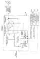
- Fig. 5 and Fig. 6 show an embodiment of a driving control system of the transfer crane and the position control apparatus of the crane of the invention.
- the transfer crane includes a trolley position detector 24 comprising a trolley track transverse motor 20 which transversely drives the transverse trolley 13, an rotor encoder connected to the motor and the like, and a reeled height detector 26 comprising a reeling motor 22, an rotor encoder connected to the motor and the like.
- the transfer crane is provided with a tool position detecting apparatus 25 which detects horizontal relative position (lateral swing) between the transverse trolley 13 and the tool 16.
- the tool position detecting apparatus 25 includes a CCD camera 25A (see Fig. 4) which shoots a tool target marker 25B which is a shooting target fixed in the container tool 16 and disposed on the transverse trolley 13.
- the tool position detecting apparatus 25 detects the horizontal relative position (lateral swing) of the tool 16 with respect to the transverse trolley 13 by the shoot data (tool target marker detection image signal) of the CCD camera 25A.
- the trolley track transverse motor 20 and the reeling motor 22 are driven by electric control of a trolley motor driving apparatus 21 and a reeling motor driving apparatus 23.
- a trolley speed command signal and a unreeling speed command signal are sent from a crane control apparatus 30 to these driving apparatuses 21 and 23, respectively.
- the crane control apparatus 30 comprises an estimator/calculator 31 which estimates and calculates the lateral swing of the tool 16, a load position control unit 32, a landing time calculator 33, an unreeling delay time determining unit 34 and an unreeling speed determining unit 35.
- the estimator/calculator 31 inputs the trolley position detected by the trolley position detector 24, trolley speed obtained by differentiating the signal of the trolley position by a differentiator 36, swing displacement of the tool 16 (or of the hung container) detected by the tool position detecting apparatus 25, swinging speed obtained by differentiating the signal of the swing displacement by a differentiator 37, and trolley speed command output by the load position control unit 32. Using the input values as variables, the estimator/calculator 31 estimates and calculates a horizontal position variation (lateral swing) of the tool 16 in a state in which the container Ca is hung down by the tool 16.
- a portion surrounding by a broken line 31 shows an inner structure of the estimator/calculator 31 shown in Fig. 5 and Fig. 6.
- Input and output signals of the estimator/calculator 31 shown in Fig. 7 corresponds to a calculator 31 shown in Fig. 5 and Fig. 6.
- the estimator/calculator 31 comprises a simulation initial value setting section 31-1, a transfer crane structure, a trolley driving rope system model 31-2 (crane behavior model, hereinafter) , a swing peak amplitude detecting section 31-3 (swing peak detecting section, hereinafter) of simulation result, and a tool position control model 31-4.
- the crane behavior model 31-2 is formed by modeling behaviors such as a structure of the crane, a machine apparatus, the rope and the like to calculate a displacement of the load in the horizontal direction and the like by simulation using, as an initial value, a measurement value such as trolley position input from various detectors, trolley speed, horizontal displacement of the tool (swing) , displacement speed of the tool (swing speed.) and the like.
- the tool position control model 31-4 is a model which simulates a behavior of the load position control unit 32 included in the crane control apparatus 30.
- Gain constants K1 and K2 included in the model 31-4 are equal to K1 (38) and K2 (39) shown in Fig. 5.
- the periodical displacement of the load (container), speed of periodical displacement and the trolley position are estimated and simulated.
- a result of the estimation and simulation is a time series data of estimated load (container) position in a period during which at least the estimated load (container) position reaches the maximum amplitude. Other simulation results are variation in trolley position in the period.
- the swing peak detecting section 31-3 detects the maximum amplitude from the time series data of the estimated load (container) position whish is a result of the simulation, and outputs the same. A difference between this output and the trolley position which is the simulation result is set to a target value of the load (container) position with respect to the load position control unit 32 included in the crane control apparatus 30. That is, a value obtained by deviating the trolley position estimated value by the simulation result by an amount corresponding to the maximum amplitude value obtained by the simulation is set as a set value of the load position control unit 32.
- This operation corresponds to calculation of necessary moving amount of trolley (S62 to S61), and the load position control unit 32 controls to move the position of the rope support point on the trolley to a position deviated by an amount corresponding to the maximum amplitude.
- the load position control unit 32 inputs a target value of the load position, swing displacement and swing speed of the tool 16 (load) detected by the tool position detecting apparatus 25, carries out positioning control calculation of the load such that moving completion stop position of the transverse trolley (load) 13 coincides with the target value of the load position based on the positioning control gain K1 by a positioning control gain setting device 38, carries out swing-preventing control calculation such that the swing speed becomes small based on the swing-preventing control gain K2 by a swing-preventing control setting device 39, and outputs a trolley speed command to the trolley motor driving apparatus 21.
- the landing time calculator 33 calculates time (landing time) Ts from the completion of the load position control to the landing, from a reeled height detected by the reeled height detector 26 and unreeling speed obtained by differentiation using a differentiator 40.
- the unreeling delay time determining unit 34 inputs time series data of the estimated tool position from the estimator/calculator 31, and inputs the landing time Ts by the landing time calculator 33, and as shown in Fig. 3, the unreeling delay time determining unit 34 determines the descending delay time ⁇ T of the load such that the hung container Ca lands on the subject container Cb when the horizontal direction position displacement (lateral swing) becomes maximum amplitude.
- the unreeling speed determining unit 35 determines the speed of descending (deceleration characteristics) based on the descending delay time ⁇ T of the load, and outputs the unreeling speed command to the reeling motor driving apparatus 23.
- the deceleration characteristics is set by a deceleration coefficient which has correlation to the descending delay time ⁇ T.
- the speed is reduced to a specified speed of descending (extremely low speed close to 0) at the time of landing.
- the unreeling speed control step is started.
- deceleration control of the speed of descending of the tool 16 is carried out.
- the landing time Ts calculated by the landing time calculator 33 and the unreeling delay time ⁇ T determined by the unreeling delay time determining unit 34 have been elapsed from the completion time (current time in Fig. 3) of the load position control, the hung container Ca lands on the target container Cb at the specified landing speed of descending.
- This landing timing is a time point at which the horizontal direction position displacement (lateral swing) of the tool 16 at the time of landing becomes maximum amplitude at the descending delay time ⁇ T of load, and the hung container Ca of the tool 16 lands on the target container.
- the time of landing if the coincidence of the horizontal position of the upper and lower containers is detected at the maximum amplitude, since speed of the lateral swing is zero when the lateral swing of the tool 16 becomes maximum, the hung container Ca lands at lateral swing speed 0.
- the lateral swing of the tool 16 is estimated and calculated using the trolley position, the trolley speed, the swing displacement, the swing speed, and the trolley speed command.
- estimation and calculation of the lateral swing of the tool 16 can be performed more precisely using additional information concerning the reel height and information concerning load weight.
- the lateral swing of the tool is estimated in a state in which the container is hung down from the tool, and the landing is carried out at the lateral swing maximum time point of the tool where the swing speed of the tool becomes zero. Therefore, it is unnecessary to wait until the lateral swing is eliminated, and it is possible to carry out appropriate landing.
Landscapes
- Engineering & Computer Science (AREA)
- Mechanical Engineering (AREA)
- Automation & Control Theory (AREA)
- Control And Safety Of Cranes (AREA)
Applications Claiming Priority (2)
| Application Number | Priority Date | Filing Date | Title |
|---|---|---|---|
| JP2001036015 | 2001-02-13 | ||
| JP2001036015A JP2002241079A (ja) | 2001-02-13 | 2001-02-13 | クレーンの積み付け制御方法および積み付け制御装置 |
Publications (2)
| Publication Number | Publication Date |
|---|---|
| EP1231178A2 true EP1231178A2 (fr) | 2002-08-14 |
| EP1231178A3 EP1231178A3 (fr) | 2009-04-29 |
Family
ID=18899363
Family Applications (1)
| Application Number | Title | Priority Date | Filing Date |
|---|---|---|---|
| EP02003104A Withdrawn EP1231178A3 (fr) | 2001-02-13 | 2002-02-13 | Procédé et dispositif pour contrôler l' empilement d' une charge par une grue |
Country Status (8)
| Country | Link |
|---|---|
| US (1) | US6644485B2 (fr) |
| EP (1) | EP1231178A3 (fr) |
| JP (1) | JP2002241079A (fr) |
| KR (1) | KR100427957B1 (fr) |
| CN (1) | CN1313353C (fr) |
| HK (1) | HK1047571B (fr) |
| SG (1) | SG115447A1 (fr) |
| TW (1) | TW593120B (fr) |
Cited By (4)
| Publication number | Priority date | Publication date | Assignee | Title |
|---|---|---|---|---|
| CN103309275A (zh) * | 2013-06-06 | 2013-09-18 | 洛阳涧光石化设备有限公司 | 一种延迟焦化用天车的远程操作控制系统 |
| CN113526363A (zh) * | 2020-03-30 | 2021-10-22 | 杭州国电大力机电工程有限公司 | 一种缆索起重机 |
| CN116296517A (zh) * | 2023-05-08 | 2023-06-23 | 四川经准特种设备检验有限公司 | 一种起重机械综合性能检测装置及检测方法 |
| EP4270773A4 (fr) * | 2020-12-24 | 2024-05-22 | Panasonic Intellectual Property Management Co., Ltd. | Dispositif de commande de moteur |
Families Citing this family (11)
| Publication number | Priority date | Publication date | Assignee | Title |
|---|---|---|---|---|
| DE10245970B4 (de) * | 2002-09-30 | 2008-08-21 | Siemens Ag | Verfahren bzw. Vorrichtung zur Erkennung einer Last eines Hebezeuges |
| DE10245889B4 (de) * | 2002-09-30 | 2008-07-31 | Siemens Ag | Verfahren und/oder Einrichtung zur Bestimmung einer Pendelung einer Last eines Hebezeuges |
| JP3935826B2 (ja) * | 2002-11-15 | 2007-06-27 | 三菱重工業株式会社 | 吊荷の積み付け制御方法及び制御装置並びに荷役機械 |
| US7289875B2 (en) * | 2003-11-14 | 2007-10-30 | Siemens Technology-To-Business Center Llc | Systems and methods for sway control |
| DE102008024215B4 (de) * | 2008-05-19 | 2015-08-20 | Manitowoc Crane Group France Sas | Bestimmung und Rekonstruktion von Laständerungen an Hebezeugen |
| CN101857175B (zh) * | 2010-05-26 | 2012-01-04 | 安徽英科智控股份有限公司 | 集装箱正面吊运机极限载荷的控制系统 |
| US9278832B2 (en) * | 2013-11-26 | 2016-03-08 | Institute Of Neclear Energy Research | Method of reducing computational demand for image tracking |
| CN108217487A (zh) * | 2017-12-08 | 2018-06-29 | 上海辛格林纳新时达电机有限公司 | 吊具的起升系统及控制方法 |
| CN108584716B (zh) * | 2018-05-04 | 2024-02-13 | 蛇口集装箱码头有限公司 | 一种门式起重机安全防护和作业辅助系统 |
| CN112010177B (zh) * | 2020-08-31 | 2022-04-29 | 上海驭矩信息科技有限公司 | 一种堆场地面集装箱自动着箱方法 |
| CN113479773B (zh) * | 2021-05-24 | 2023-11-24 | 武汉港迪智能技术有限公司 | 一种集装箱吊具动态下放方法 |
Citations (2)
| Publication number | Priority date | Publication date | Assignee | Title |
|---|---|---|---|---|
| US4997095A (en) | 1989-04-20 | 1991-03-05 | The United States Of America As Represented By The United States Department Of Energy | Methods of and system for swing damping movement of suspended objects |
| JPH10120362A (ja) | 1996-10-23 | 1998-05-12 | Mitsubishi Heavy Ind Ltd | クレーンの吊り荷着床制御装置 |
Family Cites Families (6)
| Publication number | Priority date | Publication date | Assignee | Title |
|---|---|---|---|---|
| FR2645846B1 (fr) * | 1989-04-14 | 1991-10-04 | Reel Sa | Dispositif de controle de la position et des oscillations d'une charge suspendue durant son transfert au moyen d'un appareil de levage |
| SE502609C2 (sv) * | 1990-03-28 | 1995-11-20 | Asea Brown Boveri | Förflyttning av gods med containerkranar |
| FR2701467B1 (fr) * | 1993-02-12 | 1995-05-12 | Caillard | Système de contrôle de commande de la vitesse de déplacement d'une charge pendulaire et appareil de levage comprenant un tel système. |
| US5443566A (en) * | 1994-05-23 | 1995-08-22 | General Electric Company | Electronic antisway control |
| US5713477A (en) * | 1995-10-12 | 1998-02-03 | Wallace, Jr.; Walter J. | Method and apparatus for controlling and operating a container crane or other similar cranes |
| US6256553B1 (en) * | 1995-11-14 | 2001-07-03 | Sime Oy | Method and device to pick up, transport and put down a load |
-
2001
- 2001-02-13 JP JP2001036015A patent/JP2002241079A/ja active Pending
-
2002
- 2002-01-30 TW TW091101582A patent/TW593120B/zh not_active IP Right Cessation
- 2002-02-05 SG SG200200665A patent/SG115447A1/en unknown
- 2002-02-07 US US10/067,313 patent/US6644485B2/en not_active Expired - Fee Related
- 2002-02-08 KR KR10-2002-0007460A patent/KR100427957B1/ko not_active IP Right Cessation
- 2002-02-13 CN CNB021186847A patent/CN1313353C/zh not_active Expired - Fee Related
- 2002-02-13 EP EP02003104A patent/EP1231178A3/fr not_active Withdrawn
- 2002-12-18 HK HK02109173.8A patent/HK1047571B/zh not_active IP Right Cessation
Patent Citations (2)
| Publication number | Priority date | Publication date | Assignee | Title |
|---|---|---|---|---|
| US4997095A (en) | 1989-04-20 | 1991-03-05 | The United States Of America As Represented By The United States Department Of Energy | Methods of and system for swing damping movement of suspended objects |
| JPH10120362A (ja) | 1996-10-23 | 1998-05-12 | Mitsubishi Heavy Ind Ltd | クレーンの吊り荷着床制御装置 |
Cited By (7)
| Publication number | Priority date | Publication date | Assignee | Title |
|---|---|---|---|---|
| CN103309275A (zh) * | 2013-06-06 | 2013-09-18 | 洛阳涧光石化设备有限公司 | 一种延迟焦化用天车的远程操作控制系统 |
| CN103309275B (zh) * | 2013-06-06 | 2016-02-03 | 洛阳涧光特种装备股份有限公司 | 一种延迟焦化用天车的远程操作控制系统 |
| CN113526363A (zh) * | 2020-03-30 | 2021-10-22 | 杭州国电大力机电工程有限公司 | 一种缆索起重机 |
| CN113526363B (zh) * | 2020-03-30 | 2023-06-16 | 杭州国电大力机电工程有限公司 | 一种缆索起重机 |
| EP4270773A4 (fr) * | 2020-12-24 | 2024-05-22 | Panasonic Intellectual Property Management Co., Ltd. | Dispositif de commande de moteur |
| CN116296517A (zh) * | 2023-05-08 | 2023-06-23 | 四川经准特种设备检验有限公司 | 一种起重机械综合性能检测装置及检测方法 |
| CN116296517B (zh) * | 2023-05-08 | 2023-07-25 | 四川经准特种设备检验有限公司 | 一种起重机械综合性能检测装置及检测方法 |
Also Published As
| Publication number | Publication date |
|---|---|
| CN1313353C (zh) | 2007-05-02 |
| CN1375445A (zh) | 2002-10-23 |
| KR100427957B1 (ko) | 2004-05-06 |
| US6644485B2 (en) | 2003-11-11 |
| HK1047571A1 (en) | 2003-02-28 |
| US20020108919A1 (en) | 2002-08-15 |
| HK1047571B (zh) | 2007-08-24 |
| KR20020066995A (ko) | 2002-08-21 |
| EP1231178A3 (fr) | 2009-04-29 |
| SG115447A1 (en) | 2005-10-28 |
| TW593120B (en) | 2004-06-21 |
| JP2002241079A (ja) | 2002-08-28 |
Similar Documents
| Publication | Publication Date | Title |
|---|---|---|
| US6644485B2 (en) | Method of and apparatus for controlling stacking of a load by a crane | |
| US5938052A (en) | Rope steadying control method and apparatus for crane or the like | |
| US6880712B2 (en) | Crane and method for controlling the crane | |
| KR100615950B1 (ko) | 현수식 반송장치 | |
| KR101841410B1 (ko) | 부하 및 위치 종속 측정 오류를 고려하는 자동화 크레인 제어기 | |
| JPH08198584A (ja) | クレーンの無人運転方法及びその装置 | |
| JP2012193022A (ja) | クレーンの振れ止め制御方法及び振れ止め制御装置 | |
| JP2019019001A (ja) | 揚重装置の積み荷受け入れ要素の回転振動を減衰する方法 | |
| CN112689608B (zh) | 用于在升降机竖井中规划和至少部分地安装升降机设备的方法 | |
| FI127422B (fi) | Menetelmä, tietokoneohjelma ja laitteisto nosturin ohjaamiseksi ja menetelmä nosturin päivittämiseksi | |
| JP7444710B2 (ja) | 昇降路内計測装置、および、昇降路内計測システム | |
| JP3935826B2 (ja) | 吊荷の積み付け制御方法及び制御装置並びに荷役機械 | |
| JP4220852B2 (ja) | トランスファークレーン | |
| US7733046B2 (en) | Motor controller and control method thereof | |
| KR101362421B1 (ko) | 크레인의 이동 제어장치 및 크레인의 이동 제어방법 | |
| JP6838781B2 (ja) | 吊り荷の振れ止め方法及びクレーン | |
| WO2023112828A1 (fr) | Dispositif de travail et procédé de commande pour dispositif de travail | |
| JP4807600B2 (ja) | 移動体システム | |
| JPH112508A (ja) | 吊荷の位置検出装置 | |
| JP6756431B2 (ja) | 吊り荷の移送方法及びクレーン | |
| JP2021091508A (ja) | レールブラケット固定部の自動計測システム | |
| FI20195848A1 (en) | Checking the position of the gripper | |
| JP2021102503A (ja) | 懸架式クレーンの制御装置及びインバータ装置 | |
| JP2000289978A (ja) | 天井クレーンの制御方法 | |
| JPS591674B2 (ja) | クレ−ンの自動制御方法及び自動クレ−ン装置 |
Legal Events
| Date | Code | Title | Description |
|---|---|---|---|
| PUAI | Public reference made under article 153(3) epc to a published international application that has entered the european phase |
Free format text: ORIGINAL CODE: 0009012 |
|
| 17P | Request for examination filed |
Effective date: 20020213 |
|
| AK | Designated contracting states |
Kind code of ref document: A2 Designated state(s): AT BE CH CY DE DK ES FI FR GB GR IE IT LI LU MC NL PT SE TR |
|
| AX | Request for extension of the european patent |
Free format text: AL;LT;LV;MK;RO;SI |
|
| PUAL | Search report despatched |
Free format text: ORIGINAL CODE: 0009013 |
|
| AK | Designated contracting states |
Kind code of ref document: A3 Designated state(s): AT BE CH CY DE DK ES FI FR GB GR IE IT LI LU MC NL PT SE TR |
|
| AX | Request for extension of the european patent |
Extension state: AL LT LV MK RO SI |
|
| 17Q | First examination report despatched |
Effective date: 20090819 |
|
| AKX | Designation fees paid |
Designated state(s): DE IT SE |
|
| STAA | Information on the status of an ep patent application or granted ep patent |
Free format text: STATUS: THE APPLICATION IS DEEMED TO BE WITHDRAWN |
|
| 18D | Application deemed to be withdrawn |
Effective date: 20120901 |