EP1229599A2 - Manufacturing method for sintered substrate of alkaline storage battery - Google Patents
Manufacturing method for sintered substrate of alkaline storage battery Download PDFInfo
- Publication number
- EP1229599A2 EP1229599A2 EP02002290A EP02002290A EP1229599A2 EP 1229599 A2 EP1229599 A2 EP 1229599A2 EP 02002290 A EP02002290 A EP 02002290A EP 02002290 A EP02002290 A EP 02002290A EP 1229599 A2 EP1229599 A2 EP 1229599A2
- Authority
- EP
- European Patent Office
- Prior art keywords
- nickel
- particles
- pore former
- substrate
- sintered
- Prior art date
- Legal status (The legal status is an assumption and is not a legal conclusion. Google has not performed a legal analysis and makes no representation as to the accuracy of the status listed.)
- Withdrawn
Links
Images


Classifications
-
- H—ELECTRICITY
- H01—ELECTRIC ELEMENTS
- H01M—PROCESSES OR MEANS, e.g. BATTERIES, FOR THE DIRECT CONVERSION OF CHEMICAL ENERGY INTO ELECTRICAL ENERGY
- H01M4/00—Electrodes
- H01M4/02—Electrodes composed of, or comprising, active material
- H01M4/64—Carriers or collectors
- H01M4/70—Carriers or collectors characterised by shape or form
- H01M4/80—Porous plates, e.g. sintered carriers
- H01M4/801—Sintered carriers
- H01M4/803—Sintered carriers of only powdered material
-
- H—ELECTRICITY
- H01—ELECTRIC ELEMENTS
- H01M—PROCESSES OR MEANS, e.g. BATTERIES, FOR THE DIRECT CONVERSION OF CHEMICAL ENERGY INTO ELECTRICAL ENERGY
- H01M4/00—Electrodes
- H01M4/02—Electrodes composed of, or comprising, active material
- H01M4/64—Carriers or collectors
- H01M4/70—Carriers or collectors characterised by shape or form
- H01M4/80—Porous plates, e.g. sintered carriers
-
- B—PERFORMING OPERATIONS; TRANSPORTING
- B22—CASTING; POWDER METALLURGY
- B22F—WORKING METALLIC POWDER; MANUFACTURE OF ARTICLES FROM METALLIC POWDER; MAKING METALLIC POWDER; APPARATUS OR DEVICES SPECIALLY ADAPTED FOR METALLIC POWDER
- B22F3/00—Manufacture of workpieces or articles from metallic powder characterised by the manner of compacting or sintering; Apparatus specially adapted therefor ; Presses and furnaces
- B22F3/10—Sintering only
- B22F3/11—Making porous workpieces or articles
- B22F3/1121—Making porous workpieces or articles by using decomposable, meltable or sublimatable fillers
- B22F3/1134—Inorganic fillers
-
- B—PERFORMING OPERATIONS; TRANSPORTING
- B22—CASTING; POWDER METALLURGY
- B22F—WORKING METALLIC POWDER; MANUFACTURE OF ARTICLES FROM METALLIC POWDER; MAKING METALLIC POWDER; APPARATUS OR DEVICES SPECIALLY ADAPTED FOR METALLIC POWDER
- B22F2998/00—Supplementary information concerning processes or compositions relating to powder metallurgy
-
- Y—GENERAL TAGGING OF NEW TECHNOLOGICAL DEVELOPMENTS; GENERAL TAGGING OF CROSS-SECTIONAL TECHNOLOGIES SPANNING OVER SEVERAL SECTIONS OF THE IPC; TECHNICAL SUBJECTS COVERED BY FORMER USPC CROSS-REFERENCE ART COLLECTIONS [XRACs] AND DIGESTS
- Y02—TECHNOLOGIES OR APPLICATIONS FOR MITIGATION OR ADAPTATION AGAINST CLIMATE CHANGE
- Y02E—REDUCTION OF GREENHOUSE GAS [GHG] EMISSIONS, RELATED TO ENERGY GENERATION, TRANSMISSION OR DISTRIBUTION
- Y02E60/00—Enabling technologies; Technologies with a potential or indirect contribution to GHG emissions mitigation
- Y02E60/10—Energy storage using batteries
-
- Y—GENERAL TAGGING OF NEW TECHNOLOGICAL DEVELOPMENTS; GENERAL TAGGING OF CROSS-SECTIONAL TECHNOLOGIES SPANNING OVER SEVERAL SECTIONS OF THE IPC; TECHNICAL SUBJECTS COVERED BY FORMER USPC CROSS-REFERENCE ART COLLECTIONS [XRACs] AND DIGESTS
- Y10—TECHNICAL SUBJECTS COVERED BY FORMER USPC
- Y10T—TECHNICAL SUBJECTS COVERED BY FORMER US CLASSIFICATION
- Y10T29/00—Metal working
- Y10T29/10—Battery-grid making
-
- Y—GENERAL TAGGING OF NEW TECHNOLOGICAL DEVELOPMENTS; GENERAL TAGGING OF CROSS-SECTIONAL TECHNOLOGIES SPANNING OVER SEVERAL SECTIONS OF THE IPC; TECHNICAL SUBJECTS COVERED BY FORMER USPC CROSS-REFERENCE ART COLLECTIONS [XRACs] AND DIGESTS
- Y10—TECHNICAL SUBJECTS COVERED BY FORMER USPC
- Y10T—TECHNICAL SUBJECTS COVERED BY FORMER US CLASSIFICATION
- Y10T29/00—Metal working
- Y10T29/49—Method of mechanical manufacture
- Y10T29/49002—Electrical device making
- Y10T29/49108—Electric battery cell making
- Y10T29/49115—Electric battery cell making including coating or impregnating
Definitions
- the present invention relates to a sintered substrate of alkaline batteries and the manufacturing method thereof.
- sintered substrates As substrate grids for electrodes of alkaline batteries including nickel-hydrogen storage batteries, sintered substrates have been commonly used.
- a sintered substrate is formed by applying nickel powder to a porous substrate made of nickel or the like, and by sintering the substrate. Among such porous substrates are punched metals and punched nickel plates. By impregnating the sintered substrate with an active material, an electrode can be formed.
- the production of alkaline batteries having a higher energy density requires an increased amount of impregnated active material, since the operation of a battery is greatly dependent on the active material.
- sintered substrates have a high porosity and hold a sufficient amount of active material in those pores.
- porous sintered substrate is attainable by using a punched metal with a reduced thickness or with an increased porosity. Though such methods are considered as valid, some other methods have been developed.
- a sintered substrate is formed by applying slurry made of nickel powder, water and pore former (hollow resinous particles) to a punched metal.
- a technique disclosed by the Japanese Patent Laid-Open Application Number S61-185685 in which a sintered substrate is formed by applying a mixture of water and metal-coated pore former particles to a punched metal and then sintering the punched metal together with the mixture.
- FIG. 3 shows an electrode that uses a sintered substrate formed based on the former technique.
- the nickel particles (FIG. 3B) and the core (punched metal) are sintered and bonded together to form a nickel framework (FIG. 3A).
- FIG. 3A shows a nickel framework
- FIG. 4 shows an electrode that uses a sintered substrate manufactured according to the latter technique.
- a punched metal and hollow spheric nickel shells (FIG.4B) are sintered together to form a nickel framework (FIG.4A).
- the nickel shells of this nickel framework (FIG. 4C) have relatively large pores, and they are joined together with some spaces in-between. Though not illustrated here for the sake of convenience, these pores and spaces are filled with an active material.
- sintered substrates with relatively high porosity.
- the sintered substrates have a problem of strength.
- Sintered substrates manufactured by the former technique have a higher porosity, with relatively large pores formed inside the nickel frameworks by the effect of the pore former . But this porous construction can cause brittle failure, including surface detachment and cracking.
- sintered substrates according to the second technique have pores of an average size generated from metal-plated pore former . But these sintered substrates do not have a sufficient level of strength, and they are weak especially against stress applied from the direction of the thickness. This can cause a problem similar to those with the first technique. Such problems can occur whether the shape of the battery is cylindrical or rectangular.
- the present invention intends to provide a manufacturing method for producing sintered substrates of alkaline batteries having high porosity and high strength.
- 'pore former refers to a substance that remains in the form of particles when a first step is completed but disappears during a second step.
- the pore former includes resinous powder which dissipates when it is burned.
- pore former is provided in the form of spheric particles having a diameter greater than that of a particle made of nickel or principally made of nickel.
- the pore former is mixed and knead with the particles that are made of nickel or principally made of nickel, to be arranged almost uniformly in spaces between the nickel particles, so that some of the spaces between them are pressurized and enlarged.
- the surfaces of the pore former particles are covered with a coating made of nickel or principally made of nickel.
- the nickel framework is constructed in such a manner that a nickel particle surrounds a nickel shell, and the nickel shell surrounds a relatively large pore. This gives strength and thickness to parts of the nickel framework surrounding relatively large pores, preventing the occurrence of brittle failure. Therefore, even with a higher porosity, the sintered substrate of the present invention can preserve the strength.
- the sintered substrate of the present invention Compared with sintered substrates manufactured by a conventional manufacturing method which uses non-Ni-coated pore former particles and particles that are made of nickel or principally made of nickel, the sintered substrate of the present invention has high strength. At the same time, the sintered substrate has a greater porosity than sintered substrates manufactured according to a conventional technique which uses only metal-plated pore former particles.
- FIG. 1 is a perspective view showing a cross-section of a cylindrical alkaline storage battery (a nickel-hydrogen storage battery) that is an embodiment of a sintered substrate manufactured by a method of the present invention.
- the sintered substrate is used for a positive electrode 1.
- the alkaline storage battery consists of a set of electrodes 4 and a cylindrical external casing 6 of AA size.
- the set of electrodes 4, impregnated with an electrolytic solution, is housed in the cylindrical external casing 6.
- the set of electrodes 4 is formed by spirally winding a positive electrode 1 and a negative electrode 2 with a separator 3 in-between.
- the negative electrode 2 is formed from a Ni-plated porous Fe substrate (e.g. a punched metal). A paste containing hydrogen-absorbing alloys is applied to the substrate before sintering.
- the negative electrode 2 is connected by a negative collector 5 to an inner base surface of the external casing 6 which serves as a negative electrode terminal.
- An opening at the tip of the external casing 6 is closed with a sealing plate 12 via a gasket 11.
- a positive electrode terminal 13 is inserted to cover a central opening 14 of the sealing plate 12.
- a valve plate 8 Between the sealing plate 12 and positive electrode terminal 13, there arranged a valve plate 8, a holding plate 9 and a coil spring 10 in this order from the bottom.
- the valve plate 8 and the holding plate 9 can work as a safety valve when they are pressed, due to the elasticity of the spring 10, against the vicinity of the central opening 14.
- the positive electrode 1 is joined by a positive collector 7 and the sealing plate 12 with the positive electrode terminal 13.
- the construction of the positive electrode 1 is described in the following.
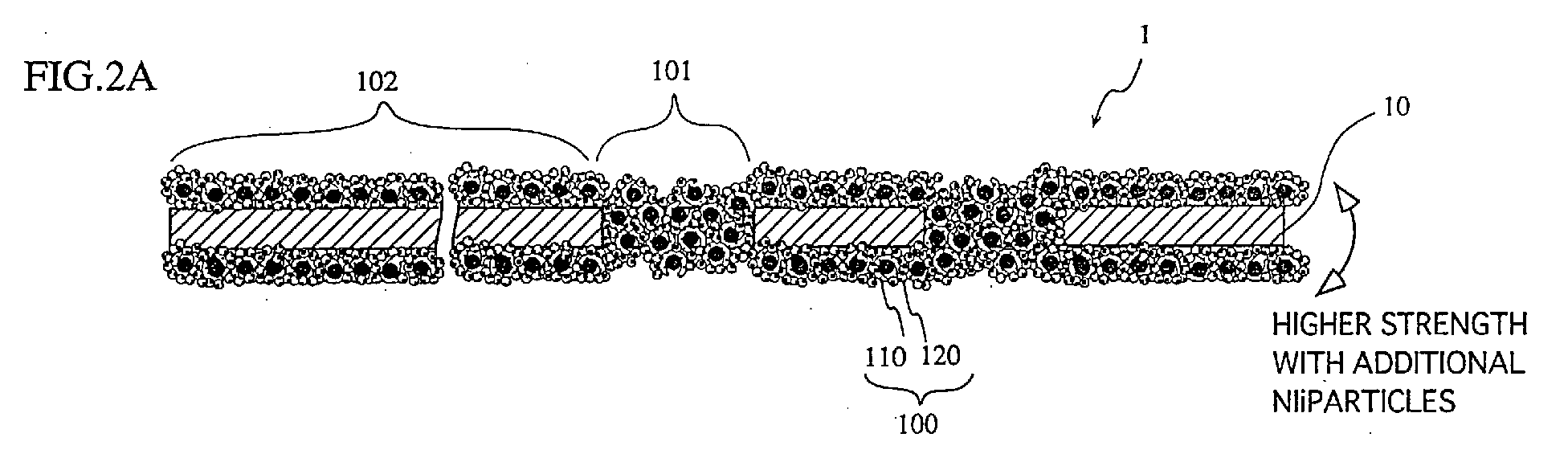
- FIG. 2A shows cross-sections of the positive electrode in this embodiment.
- the positive electrode 1 is composed of nickel frameworks 100, which uses a punched metal 10 as a porous substrate grid, nickel particles 120 and nickel shells 110 formed on the surface of the punched metal 10.
- the punched metal 10 is formed by plating a plate-like Fe core with nickel. On the surface of the punched metal 10, there are through holes 101 formed sporadically.
- the nickel framework 100 is arranged so as to fill in the through holes 101 and to cover the surfaces of the punched metals 10 in a layered form.
- the nickel framework 100 shows several characteristics that are essential to the manufacturing method of the present invention.
- the nickel framework 100 of FIG. 2B consists of the nickel particles 120 and the nickel shells 110a that are sintered together.
- the nickel shell 110a has a relatively large pore (in FIG. 2A and 2B, such relatively large pores are filled with an active material) which is formed in the place of a pore forming particle that disappeared when sintered.
- the nickel shell 110a that is what used to be a coating on the surface of the pore forming particle.
- the nickel shell 110a is obtained from a nickel coating formed on the surface of a pore forming particle.
- the pore former disappears, leaving the nickel shells 110a instead.
- the pore former particles should preferably be made of a material that dissipates during the sintering step, specifically, from resins. But the pore former can be made from any material on condition that the material, applied on a punched metal, can disappear by means of some processing.
- nickel framework 100 shows a greater porosity than a conventional nickel framework that is made up only of sintered nickel particles.
- the nickel framework 100 is constructed in such a manner that the relatively large pores are each surrounded by the nickel shell 110a, and the nickel shell 110a are each surrounded by the nickel particles, and these elements are fusion-bonded. This gives strength and thickness to parts of the nickel framework 100 surrounding the large pores, preventing the occurrence of brittle failure. This makes it possible to produce a sintered substrate having a great porosity without degrading its strength. Therefore, compared with conventional manufacturing methods for producing sintered substrates from non-Ni-coated particles or only from metal-plated pore former particles, the manufacturing method of the present invention can produce a sintered substrate with high strength and high porosity.
- the sintered substrate is filled with an active material. Any commonly used methods can serve for this purpose, including impregnating.
- This active material is put in the relatively small spaces 110c of the nickel framework and the relatively large pores 110b (as shown in FIG.2B, the small spaces among the nickel particles 120 are actually filled with the active material), to ensure that a formed positive electrode 1 is filled with a sufficient amount of active material in light of a conventional electrode.
- the nickel framework of the positive electrode 1 shows much higher strength against a stress applied from the direction of the thickness of the positive electrode 1, as shown in FIG. 2A, than a nickel framework composed merely of nickel shells. Therefore, when such a positive electrode is spirally wound to fit in the cylindrical external casing 6, it is less likely to suffer the formation of cracks on the surface than conventional ones.
- batteries of superior characteristics can be manufactured.
- the following describes a manufacturing method for the sintered substrate that is the embodiment of the present invention. As actual examples, a sintered substrate for the positive electrode 1 and slightly modified sintered substrates were prepared. The following also describes sintered substrates of comparative examples.
- carbonyl nickel powder having an average diameter of 2 ⁇ m and an apparent density of 0.5g/cm 3 was mixed with water and methylcellulose (carbonyl nickel powder-100%, water-100%, methylcellulose-2%, by weight), before adding 10wt% of Ni-coated pore former particles into the mixture.
- the pore former particles were made of a resin, such as acrylonitrile and methyl methacrylate, and their surfaces were coated with a nickel layer having a thickness of 1 ⁇ m to 5 ⁇ m (specifically, those particles are coated with nickel) .
- the mixture was then stirred to make slurry.
- the slurry was applied to the surface of a punched metal, or a Ni-plated Fe core, dried and sintered in a furnace at temperatures ranging from 800°C to 1000°C.
- the spheric pore former particles are made from solid resinous particles in the actual example 1
- the spheric pore former particles used for the substrate of actual example 2-A are hollow and coated with nickel (these hollow spaces are filled with a hydrocarbon having a low melting point, such as butane and methane). These hollow pore former particles are used by 8 weight percent for the actual example 2-A. Note that it is possible to make the substrate of the present invention from hollow pore former particles. At the early stage of the sintering process, a hydrocarbon that has a low boiling point and was filled in the hollow spaces disappeared, which facilitated the process of forming pores. Apart from this point, the substrate of this actual example 2-A was the same as the substrate of the actual example 1.
- the substrate of this actual example 2-B was the same as the substrate of the actual example 2-A, except that it used 10wt% of the Ni-coated hollow spheric pore former particles, as used for the actual example 2-A.
- the substrate of the actual example 2-C was the same as the substrate of the actual example 2-A, except that it used 12wt% of the Ni-coated hollow spheric pore former particles, as used for the actual example 2-A.
- the substrate of the actual example 3 was the same as the substrate of the actual example 2-A, except that it used 12wt% of Ni-coated hollow spheric pore former particles that contain 0.01% of P.
- the substrate of the comparative example 1-A was the same as the substrate of the actual example 2-A, except that it used 3wt% of hollow spheric pore former particles that were not coated with nickel.
- the substrate of the comparative example 1-B was the same as the substrate of the actual example 2-A, except that it used 4wt% of hollow spheric pore former particles that were not coated with nickel.
- the substrate of the comparative example 1-C was the same as the substrate of the actual example 2-A, except that it used 5wt% of hollow spheric pore former particles that were not coated with nickel.
- the substrate of the comparative example 2 was the same as the substrate of the actual example 1, except that it used 60wt% of the Ni-coated hollow spheric pore former particles, as used for the actual example 1.
- the sintered substrates were soaked in water for one hour.
- the porosities of the substrates were determined by the amounts of water included.
- a flat part of a pushpin-like metal was attached to the surface of the sintered substrates with adhesive.
- the forces (release forces) were measured immediately before the nickel sintered substrates were taken off from the punched metal. These forces represent the strength of the substrates.
- the substrate of the actual example 3 which uses slurry containing nickel and a small amount of P, has a greater strength than the actual example 2C.
- P acted as an assisting material in the sintering, which has made the sidereal nickel framework much stronger and thicker.
- the assisting material is a material that can help reduce a sintering temperature of nickel, including P. But it is more preferable that the assisting material is one of B, In or a combination of them.
- the effect of the present invention can be achieved whether the shape of the pore former particles contained in the slurry are hollow or solid. Also, it is not affected by how much the Ni-coated pore former particles are contained in the slurry on condition that the amount is within a range of those used for the actual examples. Also, the effect of the present invention will not suffer damage if the assisting material is contained in the pore former particles.
- the composition ratio at which the particles should be contained can be easily determined through adjustment and testing, to ensure the effect of the present invention.
- the slurry should preferably have nickel particles and Ni-coated pore former particles at a ratio ranging from 60:40 to 97:3.
- the sintered substrate should preferably be set within a range from 85% to 92%, so that the substrate has a sufficient active material holding capacity, and at the same time, is made stronger.
- the Ni-coated pore former particles should preferably have an average diameter ranging from 5 ⁇ m to 70 ⁇ m, and the nickel particles should preferably have an average diameter ranging from 1 ⁇ m to 5 ⁇ m.
- the present invention can be applied to other alkaline batteries, such as nickel cadmium batteries.
Landscapes
- Chemical & Material Sciences (AREA)
- Chemical Kinetics & Catalysis (AREA)
- Electrochemistry (AREA)
- General Chemical & Material Sciences (AREA)
- Engineering & Computer Science (AREA)
- Manufacturing & Machinery (AREA)
- Mechanical Engineering (AREA)
- Cell Electrode Carriers And Collectors (AREA)
- Battery Electrode And Active Subsutance (AREA)
- Powder Metallurgy (AREA)
Abstract
Description
| Actual Example 1 | Actual Example 2A to 2C | Actual Example 3 | Comparative Example 1A to 1C | Comparative Example 2 | |
| pore former particles | spheric | spheric and hollow | spheric and hollow | spheric and hollow | spheric and hollow |
| Nickel-coated? | Yes | Yes | Yes | No | Yes |
| Contains P? | No | No | Yes | No | No |
| Actual Examples | 1 | | 2B | 2C | 3 | |
| Porosity(%) | 90 | 87 | 89 | 91 | 91 | |
| Strength(N/cm2) | 400 | 425 | 420 | 405 | 420 |
| Comparative Example | | 1B | 1C | 2 | |
| Porosity(%) | 87 | 89 | 91 | 91 | |
| Strength(N/cm2) | 160 | 132 | 100 | 205 |
Claims (7)
- A manufacturing method for a sintered substrate of an alkaline storage battery, comprising:a first step for mixing particles with a pore former and applying the mixture to a porous substrate, wherein the particles are made of nickel or principally made of nickel, and the pore former is provided in the form of particles which each have a coating made of nickel or principally made of nickel; anda second step for sintering the porous substrate and the applied mixture.
- The manufacturing method of Claim 1,
wherein the particles and the pore former are mixed at a ratio ranging from 60wt%:40wt% to 97wt%:3wt%, inclusive. - The manufacturing method of any of Claims 1 or 2,
wherein the pore former contains an element that has an effect of lowering a sintering temperature of nickel. - The manufacturing method of Claim 3,
wherein the element that lowers the sintering temperature of nickel is at least one element selected from the group consisting of P, B and In. - The manufacturing method of Claim 1,
wherein the pore former decompose or disappear in the second step. - The manufacturing method of Claim 2,
wherein the pore former is made of a flammable organic material. - An alkaline storage battery having a positive electrode, a separator and a negative electrode being spirally wound together, the positive electrode comprising:wherein the plurality of particles are made of nickel or principally made of nickel, wherein at least a portion of an internal surface of the pore is covered with a coating that is made of nickel or principally made of nickel.a porous substrate;a framework having a plurality of pores therein and being composed of a plurality of particles, the particles covering a surface of the substrate; andan active material,
Applications Claiming Priority (2)
| Application Number | Priority Date | Filing Date | Title |
|---|---|---|---|
| JP2001024329 | 2001-01-31 | ||
| JP2001024329A JP2002231252A (en) | 2001-01-31 | 2001-01-31 | Method of manufacturing sintered substrate for alkaline storage battery |
Publications (2)
| Publication Number | Publication Date |
|---|---|
| EP1229599A2 true EP1229599A2 (en) | 2002-08-07 |
| EP1229599A3 EP1229599A3 (en) | 2003-12-17 |
Family
ID=18889484
Family Applications (1)
| Application Number | Title | Priority Date | Filing Date |
|---|---|---|---|
| EP02002290A Withdrawn EP1229599A3 (en) | 2001-01-31 | 2002-01-30 | Manufacturing method for sintered substrate of alkaline storage battery |
Country Status (6)
| Country | Link |
|---|---|
| US (1) | US6849361B2 (en) |
| EP (1) | EP1229599A3 (en) |
| JP (1) | JP2002231252A (en) |
| KR (1) | KR20020064193A (en) |
| CN (1) | CN1246919C (en) |
| TW (1) | TW541748B (en) |
Cited By (4)
| Publication number | Priority date | Publication date | Assignee | Title |
|---|---|---|---|---|
| US6849361B2 (en) * | 2001-01-31 | 2005-02-01 | Sanyo Electric Co., Ltd. | Manufacturing method for sintered substrate of alkaline storage battery |
| EP1528613A1 (en) * | 2003-10-28 | 2005-05-04 | TDK Corporation | Functional porous film, porous metal film and methods of manufacturing such films |
| EP2865466A1 (en) * | 2013-10-22 | 2015-04-29 | Linde Aktiengesellschaft | Method for modifying the surface structure of a metal body |
| DE102013226751A1 (en) * | 2013-12-19 | 2015-06-25 | Siemens Aktiengesellschaft | Method for producing at least one energy storage component for an electrical energy store |
Families Citing this family (11)
| Publication number | Priority date | Publication date | Assignee | Title |
|---|---|---|---|---|
| DE10150948C1 (en) * | 2001-10-11 | 2003-05-28 | Fraunhofer Ges Forschung | Process for the production of sintered porous bodies |
| US8020805B2 (en) * | 2006-07-31 | 2011-09-20 | The United States Of America As Represented By The Administrator Of The National Aeronautics And Space Administration | High altitude airship configuration and power technology and method for operation of same |
| JP4483880B2 (en) * | 2007-03-15 | 2010-06-16 | セイコーエプソン株式会社 | Molded body forming composition, degreased body and sintered body |
| JP5164412B2 (en) * | 2007-03-31 | 2013-03-21 | 三洋電機株式会社 | Alkaline storage battery and method for manufacturing sintered substrate |
| US9446953B2 (en) | 2007-07-12 | 2016-09-20 | The United States Of America As Represented By The Administrator Of The National Aeronautics And Space Administration | Fabrication of metallic hollow nanoparticles |
| DE102015120057A1 (en) * | 2015-11-19 | 2017-05-24 | Zentrum für Sonnenenergie- und Wasserstoff-Forschung Baden-Württemberg Gemeinnützige Stiftung | Nickel electrode, self-supporting nickel layer, process for their preparation and their use |
| US20180138110A1 (en) * | 2016-11-17 | 2018-05-17 | Texas Instruments Incorporated | Enhanced Adhesion by Nanoparticle Layer Having Randomly Configured Voids |
| US9865527B1 (en) | 2016-12-22 | 2018-01-09 | Texas Instruments Incorporated | Packaged semiconductor device having nanoparticle adhesion layer patterned into zones of electrical conductance and insulation |
| US9941194B1 (en) | 2017-02-21 | 2018-04-10 | Texas Instruments Incorporated | Packaged semiconductor device having patterned conductance dual-material nanoparticle adhesion layer |
| DE102017110863B4 (en) | 2017-05-18 | 2021-02-04 | Zentrum für Sonnenenergie- und Wasserstoff-Forschung Baden-Württemberg | Nickel electrode, process for its manufacture and its use |
| JP7333300B2 (en) * | 2020-10-26 | 2023-08-24 | プライムプラネットエナジー&ソリューションズ株式会社 | Electrode manufacturing method, battery manufacturing method, electrode and battery |
Family Cites Families (29)
| Publication number | Priority date | Publication date | Assignee | Title |
|---|---|---|---|---|
| US3290982A (en) * | 1964-03-20 | 1966-12-13 | Huck Mfg Co | Lockbolt construction including swaged nut |
| US3938865A (en) * | 1974-04-01 | 1976-02-17 | Rouverol William S | Cageless roller bearing |
| US4157675A (en) * | 1975-01-17 | 1979-06-12 | King John O Jr | Filled breakneck fastener |
| US3962775A (en) * | 1975-01-17 | 1976-06-15 | King John O Jun | Method of forming a joint using a guide fastener |
| US4006945A (en) * | 1975-03-06 | 1977-02-08 | Buildex Incorporated | Roller bearing assembly |
| US4203346A (en) * | 1977-06-13 | 1980-05-20 | Vsi Corporation | Blind bolt fastener for low bearing strength materials |
| US4198895A (en) * | 1978-03-24 | 1980-04-22 | Huck Manufacturing Company | Fatigue performance collars and lockbolt construction |
| US4437805A (en) * | 1979-04-03 | 1984-03-20 | Huck Manufacturing Company | Multigrip fastener |
| US4324518A (en) * | 1979-07-13 | 1982-04-13 | Huck Manufacturing Company | Dish compensating flush head fastener |
| IN153206B (en) * | 1980-01-09 | 1984-06-16 | Yardney Electric Corp | |
| US4472096A (en) * | 1981-04-14 | 1984-09-18 | Huck Manufacturing Company | Optimized fastener construction system and method |
| JPS59158047A (en) * | 1983-02-28 | 1984-09-07 | 松下電工株式会社 | Leakage breaker |
| DE3327623A1 (en) * | 1983-07-30 | 1985-02-07 | FAG Kugelfischer Georg Schäfer KGaA, 8720 Schweinfurt | SOLID WINDOW CAGE FOR CYLINDER ROLL BEARINGS |
| US4813834A (en) * | 1985-08-01 | 1989-03-21 | Huck Manufacturing Company | Fit-up fastener with flexible tab-like retaining structure and method of making same |
| JPH0734366B2 (en) * | 1986-07-22 | 1995-04-12 | 三洋電機株式会社 | Battery electrode manufacturing method |
| JPS63114068A (en) * | 1986-10-30 | 1988-05-18 | Sanyo Electric Co Ltd | Manufacture of electrode for battery |
| JPH068338Y2 (en) * | 1987-12-23 | 1994-03-02 | 光洋精工株式会社 | Compound cylindrical roller bearing |
| US4900205A (en) * | 1988-08-15 | 1990-02-13 | Huck Manufacturing Co. | Blind fastener forming a blind head with a large effective area |
| US5007781A (en) * | 1990-09-10 | 1991-04-16 | General Dynamics Corporation, Convair Division | Tapered split-bushing fastener |
| US5213460A (en) * | 1991-05-24 | 1993-05-25 | Huck International, Inc. | High strength blind bolt with uniform high clamp over an extended grip range |
| JPH08227715A (en) * | 1995-02-21 | 1996-09-03 | Shin Kobe Electric Mach Co Ltd | Manufacturing method of nickel sintered substrate |
| DE29619498U1 (en) * | 1996-11-09 | 1997-01-02 | Skf Gmbh, 97421 Schweinfurt | Cylindrical roller bearings with a comb cage |
| KR200152266Y1 (en) * | 1997-04-08 | 1999-07-15 | 윤석태 | Cylindrical roller bearing |
| IT1293628B1 (en) * | 1997-07-18 | 1999-03-08 | Skf Ind Spa | ROLLING BODY CONTAINMENT CONTROL STRUCTURE OF A ROLLING BEARING, IN PARTICULAR OF A ROLLER BEARING |
| JPH11344035A (en) * | 1998-03-31 | 1999-12-14 | Nippon Seiko Kk | Cylindrical roller bearing |
| DE19932447B4 (en) * | 1998-07-10 | 2004-03-11 | Nsk Ltd. | Cylindrical roller bearings |
| IT1308402B1 (en) * | 1999-03-03 | 2001-12-17 | Cselt Centro Studi Lab Telecom | PROCEDURE AND DEVICE FOR COUPLING OPTICAL FIBERS AND OPTOELECTRONIC COMPONENTS. |
| CA2314547A1 (en) * | 2000-07-25 | 2002-01-25 | Yvon Rancourt | Disc brake housing |
| JP2002231252A (en) * | 2001-01-31 | 2002-08-16 | Sanyo Electric Co Ltd | Method of manufacturing sintered substrate for alkaline storage battery |
-
2001
- 2001-01-31 JP JP2001024329A patent/JP2002231252A/en active Pending
-
2002
- 2002-01-25 US US10/055,373 patent/US6849361B2/en not_active Expired - Fee Related
- 2002-01-30 EP EP02002290A patent/EP1229599A3/en not_active Withdrawn
- 2002-01-30 TW TW091101521A patent/TW541748B/en not_active IP Right Cessation
- 2002-01-31 CN CNB021033439A patent/CN1246919C/en not_active Expired - Fee Related
- 2002-01-31 KR KR1020020005511A patent/KR20020064193A/en not_active Withdrawn
Cited By (4)
| Publication number | Priority date | Publication date | Assignee | Title |
|---|---|---|---|---|
| US6849361B2 (en) * | 2001-01-31 | 2005-02-01 | Sanyo Electric Co., Ltd. | Manufacturing method for sintered substrate of alkaline storage battery |
| EP1528613A1 (en) * | 2003-10-28 | 2005-05-04 | TDK Corporation | Functional porous film, porous metal film and methods of manufacturing such films |
| EP2865466A1 (en) * | 2013-10-22 | 2015-04-29 | Linde Aktiengesellschaft | Method for modifying the surface structure of a metal body |
| DE102013226751A1 (en) * | 2013-12-19 | 2015-06-25 | Siemens Aktiengesellschaft | Method for producing at least one energy storage component for an electrical energy store |
Also Published As
| Publication number | Publication date |
|---|---|
| CN1369924A (en) | 2002-09-18 |
| US6849361B2 (en) | 2005-02-01 |
| US20020150821A1 (en) | 2002-10-17 |
| EP1229599A3 (en) | 2003-12-17 |
| KR20020064193A (en) | 2002-08-07 |
| JP2002231252A (en) | 2002-08-16 |
| TW541748B (en) | 2003-07-11 |
| CN1246919C (en) | 2006-03-22 |
Similar Documents
| Publication | Publication Date | Title |
|---|---|---|
| EP1229599A2 (en) | Manufacturing method for sintered substrate of alkaline storage battery | |
| US5851599A (en) | Battery electrode substrate and process for producing the same | |
| JPH11339814A (en) | Manufacture of electrode for alkaline storage battery | |
| JPH10284076A (en) | Alkaline storage battery and method for manufacturing electrode thereof | |
| JP3386634B2 (en) | Alkaline storage battery | |
| JPH10241697A (en) | Electrode for alkaline storage battery and method for producing the same | |
| US7588861B2 (en) | Battery electrode producing method of filling active material into a metal coated fabric substrate | |
| JP3478030B2 (en) | Alkaline storage battery | |
| US7976986B2 (en) | Sintered substrate and alkaline storage battery using the substrate | |
| JP4849856B2 (en) | Hydrogen storage alloy electrode, manufacturing method thereof, and alkaline storage battery | |
| JP5213312B2 (en) | Alkaline storage battery | |
| JPS63266770A (en) | Sealed alkaline storage battery | |
| JPH10334899A (en) | Manufacturing method of alkaline storage battery and its electrode | |
| JPH0589876A (en) | Manufacture of ni electrode for alkaline storage battery | |
| JP2003288897A (en) | Manufacturing method of alkaline storage cell | |
| JP2002075338A (en) | Positive electrode mixture molding and battery | |
| JP2002110131A (en) | Separator material for alkaline secondary battery and method for producing alkaline secondary battery | |
| JP2010129196A (en) | Method of manufacturing alkaline dry cell | |
| JP2004111131A (en) | Paste type nickel electrode and its manufacturing method | |
| JPH0251874A (en) | Alkaline zinc lead-acid battery | |
| JP2001351672A (en) | Alkali storage battery | |
| KR19990000596U (en) | Negative plate of a secondary battery | |
| JPH0696760A (en) | Manufacture of cadmium negative electrode for alkaline storage battery | |
| JP2007026716A (en) | Alkaline battery | |
| JPH11288725A (en) | Electrode for alkaline storage battery, method for producing the same, and alkaline storage battery |
Legal Events
| Date | Code | Title | Description |
|---|---|---|---|
| PUAI | Public reference made under article 153(3) epc to a published international application that has entered the european phase |
Free format text: ORIGINAL CODE: 0009012 |
|
| AK | Designated contracting states |
Kind code of ref document: A2 Designated state(s): AT BE CH CY DE DK ES FI FR GB GR IE IT LI LU MC NL PT SE TR |
|
| AX | Request for extension of the european patent |
Free format text: AL;LT;LV;MK;RO;SI |
|
| PUAL | Search report despatched |
Free format text: ORIGINAL CODE: 0009013 |
|
| AK | Designated contracting states |
Kind code of ref document: A3 Designated state(s): AT BE CH CY DE DK ES FI FR GB GR IE IT LI LU MC NL PT SE TR |
|
| AX | Request for extension of the european patent |
Extension state: AL LT LV MK RO SI |
|
| RIC1 | Information provided on ipc code assigned before grant |
Ipc: 7H 01M 4/80 B Ipc: 7H 01M 4/66 A |
|
| 17P | Request for examination filed |
Effective date: 20040503 |
|
| AKX | Designation fees paid |
Designated state(s): DE FR GB |
|
| STAA | Information on the status of an ep patent application or granted ep patent |
Free format text: STATUS: THE APPLICATION HAS BEEN WITHDRAWN |
|
| 18W | Application withdrawn |
Effective date: 20071116 |