EP1229269A1 - Getriebe - Google Patents
Getriebe Download PDFInfo
- Publication number
- EP1229269A1 EP1229269A1 EP00974852A EP00974852A EP1229269A1 EP 1229269 A1 EP1229269 A1 EP 1229269A1 EP 00974852 A EP00974852 A EP 00974852A EP 00974852 A EP00974852 A EP 00974852A EP 1229269 A1 EP1229269 A1 EP 1229269A1
- Authority
- EP
- European Patent Office
- Prior art keywords
- water
- power transmission
- fluid
- transmission apparatus
- bearings
- Prior art date
- Legal status (The legal status is an assumption and is not a legal conclusion. Google has not performed a legal analysis and makes no representation as to the accuracy of the status listed.)
- Granted
Links
- 230000005540 biological transmission Effects 0.000 title claims abstract description 60
- XLYOFNOQVPJJNP-UHFFFAOYSA-N water Substances O XLYOFNOQVPJJNP-UHFFFAOYSA-N 0.000 claims abstract description 95
- 239000012530 fluid Substances 0.000 claims abstract description 89
- 230000008878 coupling Effects 0.000 claims abstract description 40
- 238000010168 coupling process Methods 0.000 claims abstract description 40
- 238000005859 coupling reaction Methods 0.000 claims abstract description 40
- 230000001050 lubricating effect Effects 0.000 claims abstract description 32
- 238000007789 sealing Methods 0.000 description 8
- 238000001816 cooling Methods 0.000 description 7
- 238000007599 discharging Methods 0.000 description 4
- 239000003595 mist Substances 0.000 description 4
- 238000009434 installation Methods 0.000 description 2
- 231100000989 no adverse effect Toxicity 0.000 description 2
- 239000002699 waste material Substances 0.000 description 2
- 238000004891 communication Methods 0.000 description 1
- 230000009977 dual effect Effects 0.000 description 1
- 230000000694 effects Effects 0.000 description 1
- 230000007613 environmental effect Effects 0.000 description 1
- 238000003912 environmental pollution Methods 0.000 description 1
- 239000004519 grease Substances 0.000 description 1
- 238000012423 maintenance Methods 0.000 description 1
- 239000002245 particle Substances 0.000 description 1
- 230000001681 protective effect Effects 0.000 description 1
- 238000013022 venting Methods 0.000 description 1
Images


Classifications
-
- F—MECHANICAL ENGINEERING; LIGHTING; HEATING; WEAPONS; BLASTING
- F16—ENGINEERING ELEMENTS AND UNITS; GENERAL MEASURES FOR PRODUCING AND MAINTAINING EFFECTIVE FUNCTIONING OF MACHINES OR INSTALLATIONS; THERMAL INSULATION IN GENERAL
- F16D—COUPLINGS FOR TRANSMITTING ROTATION; CLUTCHES; BRAKES
- F16D33/00—Rotary fluid couplings or clutches of the hydrokinetic type
- F16D33/18—Details
-
- F—MECHANICAL ENGINEERING; LIGHTING; HEATING; WEAPONS; BLASTING
- F16—ENGINEERING ELEMENTS AND UNITS; GENERAL MEASURES FOR PRODUCING AND MAINTAINING EFFECTIVE FUNCTIONING OF MACHINES OR INSTALLATIONS; THERMAL INSULATION IN GENERAL
- F16D—COUPLINGS FOR TRANSMITTING ROTATION; CLUTCHES; BRAKES
- F16D33/00—Rotary fluid couplings or clutches of the hydrokinetic type
- F16D33/06—Rotary fluid couplings or clutches of the hydrokinetic type controlled by changing the amount of liquid in the working circuit
- F16D33/08—Rotary fluid couplings or clutches of the hydrokinetic type controlled by changing the amount of liquid in the working circuit by devices incorporated in the fluid coupling, with or without remote control
- F16D33/14—Rotary fluid couplings or clutches of the hydrokinetic type controlled by changing the amount of liquid in the working circuit by devices incorporated in the fluid coupling, with or without remote control consisting of shiftable or adjustable scoops
Definitions
- the present invention relates to a power transmission apparatus for transmitting power by utilizing kinetic energy of a fluid, such as a torque converter, a fluid coupling, or the like.
- a power transmission apparatus such as a fluid coupling and a torque converter having a pump impeller coupled to a drive shaft (input shaft) and a turbine impeller coupled to a driven shaft (output shaft) for transmitting power from the drive shaft to the driven shaft through a fluid filled in a casing.
- This power transmission apparatus is advantageous in that since it uses oil as a working fluid for power transmission and also uses oil to lubricate bearings thereof, a shaft sealing device is not required between a power transmission section and bearings of the transmission apparatus.
- management of oil is troublesome at the time of overhaul, and treatment of waste oil is problematic from the viewpoint of environmental issue.
- a scoop tube is used for speed control in a variable-speed fluid coupling which is one type of power transmission apparatus, then the scoop tube is controlled by a motor servo system, a pneumatic servo system, or a hydraulic servo system.
- the present invention has been made in view of the foregoing circumstances. It is therefore an object of the present invention to provide a power transmission apparatus which can use water as a working fluid for power transmission and also can use water to lubricate bearings and operate a speed-control servo mechanism.
- a power transmission apparatus for taking out kinetic energy given to a fluid for power transmission by a prime mover as rotational power, characterized in that water is used as the fluid for power transmission and a lubricating fluid for bearings in the power transmission apparatus.
- the power transmission apparatus has radial bearings comprising sleeve bearings and thrust bearings comprising spiral hydrodynamic bearings, and these radial and thrust bearings can be lubricated by water.
- a control equipment also has such a structure that water can be used by using a hydraulic servo mechanism or the like.
- the power transmission apparatus is not required to have an oil mist separator and an air breather which would normally be needed.
- a power transmission apparatus according to an embodiment of the present invention will be described below with reference to the drawings.
- a fluid coupling will be described by way of example as the power transmission apparatus.
- Fluid couplings include constant-speed fluid couplings, variable-speed fluid couplings for controlling the amount of a working fluid to be supplied to an impeller, and variable-speed fluid couplings for controlling the amount of a working fluid in a rotating section by a scoop tube while the amount of the working fluid to be supplied is being kept constant.
- a radial bearing and a thrust bearing which are used in the power transmission apparatus according to the present invention are the same, irrespective of the type of the fluid coupling.
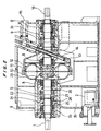
- FIG. 1 is a view showing an overall structure of a variable-speed fluid coupling according to the present invention which uses water as a working fluid for power transmission and uses a scoop tube for speed control.
- the variable-speed fluid coupling according to the present invention uses water as a working fluid for power transmission, a lubricating fluid for lubricating bearings, and a control fluid, and uses a scoop tube for speed control.
- an impeller 10 is coupled to an input shaft 7, and a runner 11 is coupled to an output shaft 16.
- An impeller casing 12 is fixed to the impeller 10.
- Each of the input shaft 7 to which the impeller 10 is fixed and the output shaft 16 to which the runner 11 is fixed is supported by two radial bearings 8 and one thrust bearing unit 9.
- the impeller 10, the runner 11, and the impeller casing 12 jointly define a working chamber (coupling section) to which water is supplied as a working fluid for power transmission.
- the fluid coupling has a water tank 35 for the working water at a lower portion thereof.
- Water delivered through a suction strainer 2 is pressurized by a pump 1, and the pressurized water has its pressure determined by a pressure determining valve 3 and is used as working water for power transmission, lubricating water for lubricating bearings, and control water.
- the pressurizing pump 1 draws in water through the strainer 2 disposed in the water tank 35, and pressurizes the water, and discharges the water having a certain pressure which is determined by a pressure setting of the pressure determining valve 3 provided at the discharge side of the pump.
- the working water for power transmission in the fluid coupling is supplied via an orifice 4 to the working chamber.
- the radial bearings 8 and the thrust bearing units 9 which support the input shaft 7 and the output shaft 16 are lubricated by water supplied from the pressurizing pump 1.
- the water is supplied to the radial bearings 8 and the thrust bearing units 9 through a lubricating water filter 5.
- a hydraulic servo mechanism is disposed for controlling a scoop tube 14. The hydraulic servo mechanism is operated by water supplied from the pressurizing pump 1.
- the water which has passed through the lubricating water filter 5 is restricted in flow rate by an orifice 6 and then supplied to the hydraulic servo mechanism.
- a servo actuator 17 rotates a pilot valve 18 to bring a groove defined in the surface of the pilot valve 18 into communication with a hole in a follow-up piston 20, thereby introducing the pressurized water into the follow-up piston 20.
- the follow-up piston 20 moves forward or backward to a position where the fluid passage created by the rotation of the pilot valve 18 is closed. Therefore, the scoop tube 14 which is directly connected to the follow-up piston 20 and has a nozzle 13 on its distal end is moved to control the amount of water in the impeller casing 12.
- the reference numeral 19 represents a housing which accommodates the follow-up piston 20 therein.
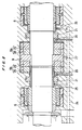
- FIG. 2 is a cross-sectional view showing the detailed structure of the variable-speed fluid coupling.
- the water supplied from the pressurizing pump 1 (see FIG. 1) for transmitting power enters from a working water supply passage 22 into a chamber behind the impeller 10, then enters from a supply hole 23 in the impeller 10 into the chamber containing vanes of the impeller 10, i.e., the working chamber.
- the water is then given kinetic energy by the rotation of the impeller 10, and flows out of the impeller 10.
- the water which has flowed out of the impeller 10 flows into the runner 11, thereby transmitting kinetic energy of the water as rotational power of the output shaft 16. Since the water used for power transmission is supplied from the supply hole 23 in the impeller 10 at all times, extra water is drawn into the scoop tube 14, and passes through a drain port 15, and is returned to the water tank 35.
- the scoop tube 14 having the nozzle 13 on its distal end is moved forward or backward by the hydraulic servo mechanism to control the amount of water in the impeller casing 12. Specifically, when the scoop tube 14 is inserted by an increased distance to reduce the amount of water in the impeller casing 12, the amount of transmitted power is reduced even if the input shaft 7 rotates at a constant rotational speed, thus reducing the rotational speed of the output shaft 16.
- the water drawn into the scoop tube 14 is discharged from the scoop tube drain port 15, and is returned to the water tank 35 in the lower portion of the variable-speed fluid coupling.
- the lubricating water for the radial bearings 8 flows through the lubricating water filter 5 (see FIG. 1) and is supplied from a lubricating water supply passage 24 through lubricating water inlets 25 having a restriction to sides of the radial bearings 8.
- the lubricating water which has flowed into the radial bearings 8 lubricates the radial bearings 8, and then flows from a passage defined in a discharge side, and is returned to the water tank 35 in the lower portion of the variable-speed fluid coupling.
- the lubricating water for the thrust bearing units 9 flows through the lubricating water filter 5 (see FIG. 1) and is supplied from the lubricating water supply passage 24 through lubricating water inlets 27 to the thrust bearing units 9.
- the lubricating water which has flowed into the thrust bearing units 9 flows from outer circumferential portions of the thrust bearing units 9 into the thrust bearings, and flows in inner circumferential portions of the thrust bearings and then along the shafts. Thereafter, the lubricating water is discharged from lubricating water drain ports 26 having a restriction unit, and is then returned to the water tank 35 in the lower portion of the variable-speed fluid coupling.
- FIG. 3 is a cross-sectional view showing the detailed structure of bearings.
- each of the radial bearings 8 comprises a sleeve bearing in the form of a cylindrical bushing.
- the lubricating water for the radial bearing 8 is supplied from the lubricating water inlet 25.
- Each of the thrust bearing units 9 comprises two types of rightward and leftward thrust bearings 9a, 9b capable of receiving thrust forces irrespective of whether the thrust forces are applied to the shaft in either a rightward or leftward direction.
- the thrust bearings 9a, 9b comprise plane bearings for receiving thrust forces with flat surfaces.
- Each of the thrust bearings 9a, 9b comprises a rotary thrust bearing 28 and a stationary thrust bearing 29.
- the rotary thrust bearing 28 and the stationary thrust bearing 29 are pressed by thrust forces and generate a surface pressure, and are lubricated by the water. At this time, in the thrust bearing which is not subjected to thrust forces, a slight gap is created between the rotary thrust bearing 28 and the stationary thrust bearing 29.
- a floating ring 21 is provided to minimize the leakage of water.
- floating rings 21 are disposed one on each side of the thrust bearing unit 9 to allow the thrust bearings to be lubricated irrespective of whether the thrust load on the shaft is applied rightward or leftward.
- the lubricating water drain port 26 has a restriction unit to allow the lubricating water to flow in the thrust bearing which is subjected to thrust forces.
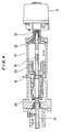
- FIG. 4 is a cross-sectional view showing the detailed structure of the hydraulic servo mechanism.
- the hydraulic servo mechanism comprises a pilot valve 18 coupled to the scoop tube 14, a servo actuator 17 for rotating the pilot valve 18, a follow-up piston 20 fixed to the pilot valve 18, and a housing 19 accommodating the follow-up piston 20 therein.
- the reference numeral 31 represents a control water inlet port for introducing the control water.
- the reference numeral 30 represents a control water drain port for discharging the control water.
- the reference numeral 32 represents an opening for venting air.
- the reference numeral 33 represents a shaft coupling interconnecting the servo actuator 17 and the pilot valve 18.
- FIGS. 5A and 5B are views showing the structure of each of the radial bearings, and FIG. 5A is a cross-sectional view and FIG. 5B is a side elevational view.
- the radial bearing 8 comprises a sleeve bearing accommodated in a housing 36, and has three grooves 8a defined in an inner surface thereof which contacts the shaft, so that the radial bearing 8 has a structure for allowing the lubricating water to flow in easily.
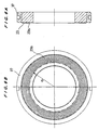
- FIGS. 6A and 6B are views showing the structure of each of the stationary thrust bearings, and FIG. 6A is a cross-sectional view and FIG. 6B is a side elevational view.
- the stationary thrust bearing 29 has very shallow spiral grooves 29s having a width of a few microns which are defined in a sliding surface thereof for bearing thrust loads.
- the lubricating water enters the spiral grooves 29s to thus produce a wedge effect for enabling the stationary thrust bearing to bear thrust forces.
- a protective tube 37 is disposed around the thrust bearing 29.
- the present invention is applied to a variable-speed fluid coupling.
- the present invention is also applicable to a torque converter comprising a casing filled with a working fluid, a pump disposed in the casing and coupled to an input shaft, a turbine disposed in the casing and coupled to an output shaft, and a stator disposed in and fixed to the casing.
- a torque converter by rotating the turbine with the energy of the working fluid given by the pump, the working fluid is returned via the stator to the pump, and the speed and torque of the output shaft are automatically variable according to the load even though the speed and torque of the input shaft are constant.
- the torque converter uses radial bearings 8 and thrust bearing units 9 which are identical to those shown in FIGS. 2, 3, 5A, 5B, 6A and 6B.
- variable-speed fluid coupling shown in FIGS. 1 through 6A and 6B has a shaft sealing structure shown in FIG. 8 which is disposed on each of both shaft ends of the input shaft 7 and the output shaft 16.
- a single labyrinth structure L is provided outside of the radial bearing 8 for preventing water as a working fluid from leaking out.
- the water-cooling device is unable to cool the high-temperature oil, thus causing the oil temperature to increase to an ignition point and leading to a fire.
- the fluid is water, even when the above situation arises, fatal problems such as a fire are not caused by an increase in the temperature of the fluid.
- the present invention relates to a power transmission apparatus for transmitting power by utilizing kinetic energy of a fluid, and can be utilized as a torque converter, a fluid coupling, or the like.
Landscapes
- Engineering & Computer Science (AREA)
- General Engineering & Computer Science (AREA)
- Mechanical Engineering (AREA)
- Hydraulic Turbines (AREA)
- Magnetic Bearings And Hydrostatic Bearings (AREA)
Applications Claiming Priority (3)
| Application Number | Priority Date | Filing Date | Title |
|---|---|---|---|
| JP31936599 | 1999-11-10 | ||
| JP31936599 | 1999-11-10 | ||
| PCT/JP2000/007872 WO2001035003A1 (fr) | 1999-11-10 | 2000-11-09 | Dispositif de transmission de puissance |
Publications (3)
| Publication Number | Publication Date |
|---|---|
| EP1229269A1 true EP1229269A1 (de) | 2002-08-07 |
| EP1229269A4 EP1229269A4 (de) | 2006-01-11 |
| EP1229269B1 EP1229269B1 (de) | 2012-03-28 |
Family
ID=18109348
Family Applications (1)
| Application Number | Title | Priority Date | Filing Date |
|---|---|---|---|
| EP00974852A Expired - Lifetime EP1229269B1 (de) | 1999-11-10 | 2000-11-09 | Getriebe |
Country Status (5)
| Country | Link |
|---|---|
| US (1) | US6725657B1 (de) |
| EP (1) | EP1229269B1 (de) |
| JP (1) | JP4310062B2 (de) |
| CN (1) | CN1177157C (de) |
| WO (1) | WO2001035003A1 (de) |
Cited By (4)
| Publication number | Priority date | Publication date | Assignee | Title |
|---|---|---|---|---|
| DE10327133A1 (de) * | 2003-06-13 | 2005-01-05 | Voith Turbo Gmbh & Co. Kg | Hydrodynamische Kupplung und Antriebseinheit mit einer hydrodynamischen Kupplung |
| DE10327154A1 (de) * | 2003-06-13 | 2005-01-13 | Voith Turbo Gmbh & Co. Kg | Verfahren zur Schmiermittelversorgung von Lagerbaueinheiten einer hydrodynamischen Kupplung und hydrodynamische Kupplung |
| WO2014177287A1 (de) * | 2013-05-03 | 2014-11-06 | Voith Patent Gmbh | Hydrodynamische maschine, insbesondere hydrodynamische kupplung |
| CN108223611A (zh) * | 2016-12-14 | 2018-06-29 | 福伊特专利有限公司 | 液力的离合器 |
Families Citing this family (10)
| Publication number | Priority date | Publication date | Assignee | Title |
|---|---|---|---|---|
| AU2007222034B2 (en) * | 2006-03-06 | 2012-08-16 | Exxonmobil Upstream Research Company | Dual end gear fluid drive starter |
| JP5154084B2 (ja) * | 2007-01-24 | 2013-02-27 | Ntn株式会社 | スラストころ軸受およびトルクコンバータ |
| WO2008090703A1 (ja) | 2007-01-24 | 2008-07-31 | Ntn Corporation | スラストころ軸受およびトルクコンバータ |
| CN201065928Y (zh) * | 2007-07-31 | 2008-05-28 | 刘时章 | 调速型液力同步器 |
| WO2013096808A1 (en) * | 2011-12-22 | 2013-06-27 | The Delfield Company, Llc | Automated method and device for cleaning of blended ice machine |
| RU2523338C2 (ru) * | 2012-01-27 | 2014-07-20 | Общество с ограниченной ответственностью "Конструкторское технологическое бюро "Техно-прогресс" | Муфта гидродинамическая регулируемая изменением наполнения |
| DE102016215739A1 (de) | 2016-08-23 | 2018-03-01 | Voith Patent Gmbh | Hydrodynamische Kupplung |
| KR101888053B1 (ko) * | 2016-12-02 | 2018-08-13 | 한국남부발전(주) | 스쿠프튜브 유압조절장치를 구비한 대용량 변속 유체 커플링 |
| EP3680519A4 (de) * | 2017-09-05 | 2021-05-12 | Eagle Industry Co., Ltd. | Gleitkomponente |
| KR102021952B1 (ko) * | 2017-11-15 | 2019-09-17 | 주식회사 나라코퍼레이션 | 폭발방지 기능이 구비된 유체커플링 |
Citations (6)
| Publication number | Priority date | Publication date | Assignee | Title |
|---|---|---|---|---|
| US3388552A (en) * | 1965-08-16 | 1968-06-18 | Fluidrive Eng Co Ltd | Hydraulic turbo couplings |
| US3521451A (en) * | 1968-08-13 | 1970-07-21 | American Standard Inc | Fluid coupling using water |
| US4023362A (en) * | 1975-06-27 | 1977-05-17 | Voith Turbo Kg | Controllable-filling hydrodynamic fluid coupling |
| US4737072A (en) * | 1984-09-20 | 1988-04-12 | Ihc Holland N.V. | Centrifugal pump |
| EP0791760A2 (de) * | 1996-02-20 | 1997-08-27 | Ebara Corporation | Wassergeschmiertes Lager oder Dichtung |
| EP0856673A2 (de) * | 1997-01-28 | 1998-08-05 | FAIGLE, Heinz | Selbstdruckerzeugende Schrägrillen-Gleitlager |
Family Cites Families (5)
| Publication number | Priority date | Publication date | Assignee | Title |
|---|---|---|---|---|
| GB1366888A (en) * | 1970-09-24 | 1974-09-18 | Fluidrive Eng Co Ltd | Scoop-trimmed fluid coupling |
| JPS60227011A (ja) | 1984-04-23 | 1985-11-12 | Ebara Corp | スラスト軸受 |
| JPS6237574A (ja) | 1985-08-12 | 1987-02-18 | Ebara Res Co Ltd | 軸封装置 |
| JPH08159080A (ja) | 1994-12-07 | 1996-06-18 | Ebara Corp | キャンドモータポンプ |
| JP3500233B2 (ja) * | 1995-09-26 | 2004-02-23 | Thk株式会社 | スピンドル装置 |
-
2000
- 2000-11-09 EP EP00974852A patent/EP1229269B1/de not_active Expired - Lifetime
- 2000-11-09 JP JP2001536899A patent/JP4310062B2/ja not_active Expired - Fee Related
- 2000-11-09 US US10/111,416 patent/US6725657B1/en not_active Expired - Lifetime
- 2000-11-09 CN CNB008155291A patent/CN1177157C/zh not_active Expired - Fee Related
- 2000-11-09 WO PCT/JP2000/007872 patent/WO2001035003A1/ja active Application Filing
Patent Citations (6)
| Publication number | Priority date | Publication date | Assignee | Title |
|---|---|---|---|---|
| US3388552A (en) * | 1965-08-16 | 1968-06-18 | Fluidrive Eng Co Ltd | Hydraulic turbo couplings |
| US3521451A (en) * | 1968-08-13 | 1970-07-21 | American Standard Inc | Fluid coupling using water |
| US4023362A (en) * | 1975-06-27 | 1977-05-17 | Voith Turbo Kg | Controllable-filling hydrodynamic fluid coupling |
| US4737072A (en) * | 1984-09-20 | 1988-04-12 | Ihc Holland N.V. | Centrifugal pump |
| EP0791760A2 (de) * | 1996-02-20 | 1997-08-27 | Ebara Corporation | Wassergeschmiertes Lager oder Dichtung |
| EP0856673A2 (de) * | 1997-01-28 | 1998-08-05 | FAIGLE, Heinz | Selbstdruckerzeugende Schrägrillen-Gleitlager |
Non-Patent Citations (1)
| Title |
|---|
| See also references of WO0135003A1 * |
Cited By (8)
| Publication number | Priority date | Publication date | Assignee | Title |
|---|---|---|---|---|
| DE10327133A1 (de) * | 2003-06-13 | 2005-01-05 | Voith Turbo Gmbh & Co. Kg | Hydrodynamische Kupplung und Antriebseinheit mit einer hydrodynamischen Kupplung |
| DE10327154A1 (de) * | 2003-06-13 | 2005-01-13 | Voith Turbo Gmbh & Co. Kg | Verfahren zur Schmiermittelversorgung von Lagerbaueinheiten einer hydrodynamischen Kupplung und hydrodynamische Kupplung |
| DE10327154B4 (de) * | 2003-06-13 | 2005-05-25 | Voith Turbo Gmbh & Co. Kg | Verfahren zur Schmiermittelversorgung von Lagerbaueinheiten einer hydrodynamischen Kupplung und hydrodynamische Kupplung |
| DE10327133B4 (de) * | 2003-06-13 | 2006-01-12 | Voith Turbo Gmbh & Co. Kg | Hydrodynamische Kupplung und Antriebseinheit mit einer hydrodynamischen Kupplung |
| US7343739B2 (en) | 2003-06-13 | 2008-03-18 | Voith Turbo Gmbh & Co. Kg | Method for supplying bearing components of a hydrodynamic clutch with lubricant and corresponding hydrodynamic clutch |
| WO2014177287A1 (de) * | 2013-05-03 | 2014-11-06 | Voith Patent Gmbh | Hydrodynamische maschine, insbesondere hydrodynamische kupplung |
| AU2014261804B2 (en) * | 2013-05-03 | 2018-02-01 | Voith Patent Gmbh | Hydrodynamic machine, in particular hydrodynamic coupling |
| CN108223611A (zh) * | 2016-12-14 | 2018-06-29 | 福伊特专利有限公司 | 液力的离合器 |
Also Published As
| Publication number | Publication date |
|---|---|
| CN1390283A (zh) | 2003-01-08 |
| EP1229269B1 (de) | 2012-03-28 |
| JP4310062B2 (ja) | 2009-08-05 |
| CN1177157C (zh) | 2004-11-24 |
| EP1229269A4 (de) | 2006-01-11 |
| US6725657B1 (en) | 2004-04-27 |
| WO2001035003A1 (fr) | 2001-05-17 |
Similar Documents
| Publication | Publication Date | Title |
|---|---|---|
| US6725657B1 (en) | Power transmission device | |
| CA1304986C (en) | Centrifugal pump bearing arrangement | |
| US3608910A (en) | Shaft seal arrangements | |
| KR100561796B1 (ko) | 물 윤활 베어링 및 밸브를 갖는 증기 터보 제너레이터 | |
| US3020719A (en) | Variable slip fluid coupling | |
| AU680092B2 (en) | Mechanical power transmission system having improved lubricant circulation apparatus | |
| US5871332A (en) | Centrifugal pump | |
| CN108700071B (zh) | 螺旋压缩机 | |
| US7014419B2 (en) | Passive improved air turbine starter lubrication system | |
| US3685617A (en) | Bearing and lubrication means | |
| JP6538550B2 (ja) | 潤滑油の漏洩を防止する軸封装置を有する流体継手 | |
| US4573810A (en) | Self-pumping hydrodynamic bearing | |
| US3002593A (en) | Power transmission | |
| US6575709B2 (en) | Pumps | |
| EP0657651A1 (de) | Pumpe | |
| EP0165689B1 (de) | Automatisches Schmierungssystem für Maschinenwellen | |
| CN107131291B (zh) | 真空驱动液压平衡系统 | |
| US3724209A (en) | Fluid unit with dump and fill control | |
| US3521451A (en) | Fluid coupling using water | |
| EP0959254B1 (de) | Kreiselpumpe mit Radialdichtring | |
| US5005990A (en) | Pump bearing system | |
| US6824350B2 (en) | Hydrodynamic sealing system for centrifugal systems | |
| KR20200086354A (ko) | 원심 보조를 갖는 사축 유압 펌프 | |
| US2784822A (en) | Hydraulically operated disconnect coupling | |
| EP3857072B1 (de) | Mehrstufige pumpe mit axialschuboptimierung |
Legal Events
| Date | Code | Title | Description |
|---|---|---|---|
| PUAI | Public reference made under article 153(3) epc to a published international application that has entered the european phase |
Free format text: ORIGINAL CODE: 0009012 |
|
| 17P | Request for examination filed |
Effective date: 20020507 |
|
| AK | Designated contracting states |
Kind code of ref document: A1 Designated state(s): AT BE CH CY DE DK ES FI FR GB GR IE IT LI LU MC NL PT SE TR |
|
| RBV | Designated contracting states (corrected) |
Designated state(s): AT BE CH DE GB IT LI |
|
| A4 | Supplementary search report drawn up and despatched |
Effective date: 20051130 |
|
| RIC1 | Information provided on ipc code assigned before grant |
Ipc: F16D 33/18 19680901AFI20051124BHEP Ipc: F16H 41/32 19680901ALI20051124BHEP Ipc: F16D 33/14 19680901ALI20051124BHEP |
|
| 17Q | First examination report despatched |
Effective date: 20070115 |
|
| GRAP | Despatch of communication of intention to grant a patent |
Free format text: ORIGINAL CODE: EPIDOSNIGR1 |
|
| GRAS | Grant fee paid |
Free format text: ORIGINAL CODE: EPIDOSNIGR3 |
|
| GRAA | (expected) grant |
Free format text: ORIGINAL CODE: 0009210 |
|
| RBV | Designated contracting states (corrected) |
Designated state(s): DE GB IT |
|
| AK | Designated contracting states |
Kind code of ref document: B1 Designated state(s): DE GB IT |
|
| REG | Reference to a national code |
Ref country code: GB Ref legal event code: FG4D |
|
| REG | Reference to a national code |
Ref country code: DE Ref legal event code: R096 Ref document number: 60047029 Country of ref document: DE Effective date: 20120516 |
|
| PLBE | No opposition filed within time limit |
Free format text: ORIGINAL CODE: 0009261 |
|
| STAA | Information on the status of an ep patent application or granted ep patent |
Free format text: STATUS: NO OPPOSITION FILED WITHIN TIME LIMIT |
|
| 26N | No opposition filed |
Effective date: 20130103 |
|
| REG | Reference to a national code |
Ref country code: DE Ref legal event code: R097 Ref document number: 60047029 Country of ref document: DE Effective date: 20130103 |
|
| PGFP | Annual fee paid to national office [announced via postgrant information from national office to epo] |
Ref country code: DE Payment date: 20181030 Year of fee payment: 19 |
|
| PGFP | Annual fee paid to national office [announced via postgrant information from national office to epo] |
Ref country code: GB Payment date: 20181107 Year of fee payment: 19 Ref country code: IT Payment date: 20181122 Year of fee payment: 19 |
|
| REG | Reference to a national code |
Ref country code: DE Ref legal event code: R119 Ref document number: 60047029 Country of ref document: DE |
|
| GBPC | Gb: european patent ceased through non-payment of renewal fee |
Effective date: 20191109 |
|
| PG25 | Lapsed in a contracting state [announced via postgrant information from national office to epo] |
Ref country code: IT Free format text: LAPSE BECAUSE OF NON-PAYMENT OF DUE FEES Effective date: 20191109 Ref country code: GB Free format text: LAPSE BECAUSE OF NON-PAYMENT OF DUE FEES Effective date: 20191109 Ref country code: DE Free format text: LAPSE BECAUSE OF NON-PAYMENT OF DUE FEES Effective date: 20200603 |