EP3857072B1 - Mehrstufige pumpe mit axialschuboptimierung - Google Patents
Mehrstufige pumpe mit axialschuboptimierung Download PDFInfo
- Publication number
- EP3857072B1 EP3857072B1 EP19783735.4A EP19783735A EP3857072B1 EP 3857072 B1 EP3857072 B1 EP 3857072B1 EP 19783735 A EP19783735 A EP 19783735A EP 3857072 B1 EP3857072 B1 EP 3857072B1
- Authority
- EP
- European Patent Office
- Prior art keywords
- pump
- multistage pump
- axial thrust
- flow
- clearance gap
- Prior art date
- Legal status (The legal status is an assumption and is not a legal conclusion. Google has not performed a legal analysis and makes no representation as to the accuracy of the status listed.)
- Active
Links
Images


Classifications
-
- F—MECHANICAL ENGINEERING; LIGHTING; HEATING; WEAPONS; BLASTING
- F04—POSITIVE - DISPLACEMENT MACHINES FOR LIQUIDS; PUMPS FOR LIQUIDS OR ELASTIC FLUIDS
- F04D—NON-POSITIVE-DISPLACEMENT PUMPS
- F04D15/00—Control, e.g. regulation, of pumps, pumping installations or systems
- F04D15/0005—Control, e.g. regulation, of pumps, pumping installations or systems by using valves
- F04D15/0022—Control, e.g. regulation, of pumps, pumping installations or systems by using valves throttling valves or valves varying the pump inlet opening or the outlet opening
-
- F—MECHANICAL ENGINEERING; LIGHTING; HEATING; WEAPONS; BLASTING
- F04—POSITIVE - DISPLACEMENT MACHINES FOR LIQUIDS; PUMPS FOR LIQUIDS OR ELASTIC FLUIDS
- F04D—NON-POSITIVE-DISPLACEMENT PUMPS
- F04D29/00—Details, component parts, or accessories
- F04D29/04—Shafts or bearings, or assemblies thereof
- F04D29/041—Axial thrust balancing
- F04D29/0416—Axial thrust balancing balancing pistons
-
- F—MECHANICAL ENGINEERING; LIGHTING; HEATING; WEAPONS; BLASTING
- F04—POSITIVE - DISPLACEMENT MACHINES FOR LIQUIDS; PUMPS FOR LIQUIDS OR ELASTIC FLUIDS
- F04D—NON-POSITIVE-DISPLACEMENT PUMPS
- F04D1/00—Radial-flow pumps, e.g. centrifugal pumps; Helico-centrifugal pumps
- F04D1/06—Multi-stage pumps
-
- F—MECHANICAL ENGINEERING; LIGHTING; HEATING; WEAPONS; BLASTING
- F04—POSITIVE - DISPLACEMENT MACHINES FOR LIQUIDS; PUMPS FOR LIQUIDS OR ELASTIC FLUIDS
- F04D—NON-POSITIVE-DISPLACEMENT PUMPS
- F04D15/00—Control, e.g. regulation, of pumps, pumping installations or systems
- F04D15/0005—Control, e.g. regulation, of pumps, pumping installations or systems by using valves
- F04D15/0011—Control, e.g. regulation, of pumps, pumping installations or systems by using valves by-pass valves
-
- F—MECHANICAL ENGINEERING; LIGHTING; HEATING; WEAPONS; BLASTING
- F04—POSITIVE - DISPLACEMENT MACHINES FOR LIQUIDS; PUMPS FOR LIQUIDS OR ELASTIC FLUIDS
- F04D—NON-POSITIVE-DISPLACEMENT PUMPS
- F04D15/00—Control, e.g. regulation, of pumps, pumping installations or systems
- F04D15/0027—Varying behaviour or the very pump
- F04D15/0033—By-passing by increasing clearance between impeller and its casing
-
- F—MECHANICAL ENGINEERING; LIGHTING; HEATING; WEAPONS; BLASTING
- F04—POSITIVE - DISPLACEMENT MACHINES FOR LIQUIDS; PUMPS FOR LIQUIDS OR ELASTIC FLUIDS
- F04D—NON-POSITIVE-DISPLACEMENT PUMPS
- F04D29/00—Details, component parts, or accessories
- F04D29/04—Shafts or bearings, or assemblies thereof
- F04D29/046—Bearings
-
- F—MECHANICAL ENGINEERING; LIGHTING; HEATING; WEAPONS; BLASTING
- F04—POSITIVE - DISPLACEMENT MACHINES FOR LIQUIDS; PUMPS FOR LIQUIDS OR ELASTIC FLUIDS
- F04D—NON-POSITIVE-DISPLACEMENT PUMPS
- F04D29/00—Details, component parts, or accessories
- F04D29/66—Combating cavitation, whirls, noise, vibration or the like; Balancing
- F04D29/669—Combating cavitation, whirls, noise, vibration or the like; Balancing especially adapted for liquid pumps
-
- F—MECHANICAL ENGINEERING; LIGHTING; HEATING; WEAPONS; BLASTING
- F05—INDEXING SCHEMES RELATING TO ENGINES OR PUMPS IN VARIOUS SUBCLASSES OF CLASSES F01-F04
- F05D—INDEXING SCHEME FOR ASPECTS RELATING TO NON-POSITIVE-DISPLACEMENT MACHINES OR ENGINES, GAS-TURBINES OR JET-PROPULSION PLANTS
- F05D2210/00—Working fluids
- F05D2210/10—Kind or type
- F05D2210/11—Kind or type liquid, i.e. incompressible
Definitions
- the present subject matter described herein relates to pumps, and, more specifically, to axial thrust compensation within multistage centrifugal pumps.
- Axial thrust is the resultant force of all the axial forces (F) acting on the pump rotor.
- Axial forces acting on the rotor in the case of a single-stage centrifugal pump includes: The axial impeller force which is the difference between the axial forces on the discharge-side and suction-side impeller shroud; Momentum force which constantly acts on the fluid contained in a defined space; resultant pressure forces arising from the static pressures up and downstream of the shaft seal on the relevant shaft cross-section; Special axial forces, e.g.
- the axial impeller force is largely determined by the impeller's axial position in relation to the diffuser.
- the rotation of the fluid handled in the discharge-side and suction-side clearances between impeller and casing exerts a strong influence on the axial pressure forces.
- the mean angular velocity (see Rotational speed) of the rotating fluid handled reaches approx. half the impeller speed.
- the inward directed clearance flow in the suction-side (i.e. outer) clearance between impeller and casing (side gap) further increases the side gap turbulences.
- the discharge-side i.e.
- axial thrust balancing includes: Mechanical: wherein complete absorption of the axial thrust via a thrust bearing (e. g. tilting pad bearing, rolling element bearing); Design-based: back-to-back arrangement of the impellers or stages (see Back-to-back impeller pump); Balancing or reduction of the axial thrust on the individual impeller via balancing holes; Balancing of the complete rotating assembly via a balancing device with automatic balancing (e. g. balance disc and balance disc seat) or partial balancing via a balance drum and double drum; Reduction at the individual impeller by back vanes.
- a thrust bearing e. g. tilting pad bearing, rolling element bearing
- Design-based back-to-back arrangement of the impellers or stages (see Back-to-back impeller pump)
- Balancing or reduction of the axial thrust on the individual impeller via balancing holes Balancing of the complete rotating assembly via a balancing device with automatic balancing (e. g. balance disc and balance disc seat) or partial
- a multistage pump is equipped with balancing piston to balance the axial thrust developed by impellers.
- the residual thrust is taken by the thrust bearings.
- the residual axial thrust is minimum at BEP flow and maximum at minimum flow condition. This restricts the use of antifriction bearing for multistage pumps due to excessive heat generation at minimum flow condition. Therefore, for higher pressure & high-speed applications, forced oil lubricated tilting pad bearings are used.
- the cost of tilting pad bearings and corresponding Tube oil plant is very high when compared with antifriction bearings with sump oil lubrication.
- DE 933 849 C discloses a device for the protection of centrifugal pumps with hydraulic axial thrust relief, in which, in order to prevent an inadmissible increase in temperature of the conveying medium in the pump at low and no load, a minimum amount of liquid is returned through the relief device into the inlet tank of the pump.
- the amount of the returned liquid is influenced by an adjustable control element, which has a minimum cross-section even at full load, which just allows the throughput of the amount of liquid necessary for hydraulic relief, wherein the control element is designed as a throttle device and the volume control is carried out depending on the pump load such that when there is a transition to low-load operation the throttling effect is reduced.
- GB 190916373 A discloses an arrangement being of that type in which, for balancing purposes, high pressure fluid is admitted to a space provided between a fixed surface of the stator and the surface of a piston or disc secured to the rotor and in which also the intensity of the pressure in the said space undergoes automatic adjustment by a displacement of the rotor consequent on a temporary lack of balance of the thrust of the fluid in the axial direction.
- GB 05848 A A.D. 1910 describes a high pressure centrifugal pump with an automatically acting axial pressure regulator, wherein a relief disc with a self-adjusting slot or passage being in communication, on one side with the pressure chamber, and on the other side with the suction chamber.
- US 8,016,545 B2 shows a centrifugal pump having a bearing.
- the bearing and the shaft have a bearing clearance there between.
- a disc is coupled to the shaft on the impeller end which is spaced apart from an inboard-bearing surface.
- a seal ring is disposed between the disc and the inboard-bearing surface.
- the shaft, the seal ring, the disc, and the inboard-bearing surface define a thrust chamber therebetween.
- the thrust chamber is in fluid communication with the impeller chamber through the bearing clearance so that an axial thrust in an inboard direction is generated by the thrust chamber.
- US 971,851 A describes a centrifugal pump, having a casing provided with a chamber, and an impeller wheel provided with a plunger adapted to play in said chamber.
- a pipe connecting said chamber with the suction and discharge of the pump comprises valves controlling the flow in said pipe.
- EP 0 224 764 A1 discloses an axial thrust compensation device for a liquid pump, which essentially consists of a stationary sleeve and a relief piston rotating in this sleeve and firmly connected to the impeller shaft, wherein the sleeve comprises sleeve channels.
- GB 1 211 243 A discloses a pump, in which an axial balancing arrangement which does not use the liquid being pumped, comprises a cylindrical chamber in the pump casing through which chamber one end of a pump shaft to be balanced extends.
- the annular chamber thus formed around the shaft including a first space arranged to be supplied by working medium at a pressure higher than that of liquid being pumped, and a second space, axially separated from said first space by means of a bearing bushing for said shaft, an annular packing member being arranged on said pump shaft and separating said first space from the flow space of the pump.
- a balancing disc being arranged on the pump shaft at the end thereof remote from the flow space of the pump. Operation of the pump causing axial movement of the balancing disc either toward or away from a seat on the casing so as to create a variable gap for throughflow of the working medium, and the bearing bushing being provided with throttling ports interconnecting said first and second spaces for throughflow of the working medium.
- JP S58 10195 A describes a pump having an axial thrust balancing disc attached to the shaft wherein a valve device is provided in the disc.
- the principal objective of the present invention is to provide a bypass system to reduce the residual axial thrust at part load condition for multistage pumps.
- Another object of the present subject matter is to allow use of antifriction bearings for higher pressure applications in multistage pumps.
- Another object of the present subject matter is to reduce the size of tilting pad thrust bearing and the corresponding lube oil .pump/plant for pumps with forced oil lubricated bearings.
- Another object of the present subject matter is to provide a simple, cost effective, and efficiently designed bypass system for multistage pumps that is distinct from all conventional designs.
- the present invention relates to a multistage pump (500) with axial thrust optimization.
- the multistage pump (500) includes a bypass system (502) configured for the axial thrust optimization.
- the bypass system (502) includes a throttle bush (504) provided proximally to a clearance gap ("Se"), wherein the throttle bush (504) defines a bypass line (506), such that the clearance gap ("Se") is configured to receive a balancing flow through the bypass line (506) for increasing a pressure in the clearance gap ("Se”) for axial thrust optimization.
- the bypass system (102) is coupled to the pump discharge nozzle (101).
- the bypass system (102) includes a throttle valve (104) operatively coupled to the pump discharge nozzle (101), and a bypass line (106) provided within the multistage pump (100), the bypass line (106) being coupled to the throttle valve (104) and a clearance gap ("Se"), wherein the clearance gap ("Se") is configured to receive a balancing flow through the bypass line (106) for increasing a pressure in the clearance gap ("Se”) for axial thrust optimization.
- the present disclosure presents embodiments for a multistage pump (100, 500) with axial thrust optimization.
- a multistage pump (100) with axial thrust optimization includes a pump discharge nozzle (101); and a bypass system (102) coupled to the pump discharge nozzle (101).
- the bypass system (102) includes a throttle valve (104) operatively coupled to the pump discharge nozzle (101), and a bypass line (106) provided within the multistage pump (100), the bypass line (106) being coupled to the throttle valve (104) and a clearance gap ("Se"), wherein the clearance gap ("Se") is configured to receive a balancing flow through the bypass line (106) for increasing a pressure in the clearance gap ("Se”) for axial thrust optimization.
- a multistage pump (500) with axial thrust optimization includes a bypass system (502) configured for the axial thrust optimization.
- the bypass system (502) includes a throttle bush (504) provided proximally to a clearance gap ("Se"), wherein the throttle bush (504) defines a bypass line (506), such that the clearance gap ("Se") is configured to receive a balancing flow through the bypass line (506) for increasing a pressure in the clearance gap ("Se”) for axial thrust optimization.
- Centrifugal pumps are based on the working principle of transferring energy to a fluid by altering its angular momentum by means of a torque which is transmitted from an evenly rotating impeller to the fluid flowing through it.
- a centrifugal pump can be described as driven machinery considering the direction of energy flow, turbomachinery considering the nature of energy conversion, or hydraulic turbomachinery considering the nature of the fluid.
- Centrifugal pumps are able to continuously pump high flow rates at high and very high pressure. For high flow rates centrifugal pumps are clearly more cost-effective and reliable than positive displacement pumps.
- centrifugal pumps are axial flow pumps, mixed flow pumps, radial flow pumps and side channel pumps. Further, the centrifugal pumps may be of single stage or multistage and are provided with bearings.
- the bearing is an element frequently used in centrifugal pump construction that allows a moving component to slide within a stationary component. Further, the bearings may be one of a radial plain bearing or an axial thrust bearing.
- the moving part is the pin or journal of the axle or shaft; the stationary part is the bearing shell and moving part of an axial (thrust) plain bearing is the thrust collar or plate.
- the axial (thrust) plain bearings are subdivided into hydrodynamic, hydrostatic and combined hydrostatic-hydrodynamic plain bearings for special applications. Both basic design types must allow sufficient axial shaft movement to accommodate the lubricant film thickness, which varies according to load, viscosity of the lubricant, and sliding velocity
- All rotors are supported on bearings which are located in a bearing housing. Forces seen by a rotor are transmitted through the bearings to the bearing housing, then to the structure on which the bearing housing is mounted or connected.
- the bearings are subjected to forces acting in both radial and / or axial direction relative to the axis of rotation.
- Bearings are either of antifriction type or of plain bearing type.
- Antifriction bearing systems are self-contained simpler units with reduced load carrying capacity at higher speeds compared to plain bearings (The term load is used to represent the forces transmitted through a bearing).
- Plain bearings as described earlier, require external lubricating oil system. While, antifriction bearing works without such an external lubricating system.
- multistage centrifugal pumps are provided with a balancing device.
- the balancing device on centrifugal pumps is designed to fully or partially compensate axial thrust generated by the pump rotor. Designs incorporating a single balance drum or double drum require a thrust bearing to absorb the residual axial thrust.
- the balancing device When the centrifugal pump is in operation, the balancing device requires a certain amount of balancing flow through the clearance gap between the balancing device's rotating and non-rotating parts. The balance flow is subjected to considerable throttling on its way through the gap. This pressure loss results in an axial force acting upon the balancing device which counteracts the impeller's axial thrust and effects the required balancing. Balancing devices are used when the axial thrust involved is extremely high, as is the case with super-pressure pumps.
- Fig. 1 illustrate a standard axial thrust balancing system comprising of a balancing double piston.
- the pressure drop at various location in the balancing piston is indicated in Fig. 1 .
- About 90% of the impeller thrust load is balanced by the balancing piston while remaining 10% load is accommodated by the thrust bearings.
- the balancing piston is provided with a balancing flow.
- the balancing flow is the volume flow required to operate the balancing device of a centrifugal pump. Although it increases the clearance gap losses, it still constitutes an efficient and cost-saving design for axial thrust balancing.
- Due to the fixed diameter of the balancing piston it can be designed for only one operating point.
- the impeller axial thrust is minimum at best efficiency point (BEP) while it is maximum at part load (minimum flow condition).
- BEP best efficiency point
- minimum flow condition minimum flow condition
- Fig. 3 illustrates a schematic view of a multistage pump (100) with axial thrust optimization in accordance with an embodiment of the present disclosure.
- the multistage pump (100) is provided with a bypass system (102) for optimizing the axial thrust.
- bypass means to circumvent or bridge.
- centrifugal pump technology it refers to a line that plays a key role in closed-loop control or as a balancing device. In the context of closed-loop control, it is possible to operate a centrifugal pump with a higher flow rate than that which is usable in the piping.
- a bypass flow is branched off, which can either be routed back to the pump suction nozzle directly from a pump discharge nozzle (101) through a narrow loop or reintegrated with the suction-side flow (after a delay) via different equipment such as a condenser and cooling unit.
- the bypass is used to compensate axial thrust in boiler feed pumps.
- bypass system (102) with the multistage pump (100).
- the bypass flow is branched off via an automatic recirculation valve that is fitted to the discharge nozzle, usually of high-pressure and super-pressure pumps (e. g. boiler feed pumps).
- the bypass system (102) is configured to increase pressure P1' (Refer Figs. 3 and 5 ) at only minimum flow condition and thereby reduce the unbalanced axial thrust acting on the multistage pump (100). Further, the bypass system (102) is configured to remain inactive at rated / BEP flow.
- the bypass system (102) coupled to the pump discharge nozzle (101) includes a throttle valve (104) operatively coupled to the pump discharge nozzle (101), and a bypass line (106) provided within the multistage pump (100), the bypass line (106) being coupled to the throttle valve (104) and a clearance gap ("Se"), wherein the clearance gap ("Se") is configured to receive a balancing flow through the bypass line (106) for increasing a pressure P1' in the clearance gap ("Se") for axial thrust optimization.
- the throttle valve (104) may be actuated manually; automatically; or semi-automatically. Further, the throttle valve (104) is operated at desired part load flow and the pressure P1' in the clearance gap ("Se") is increased to a pre-determined calculated value which leads to reduction in residual axial thrust.
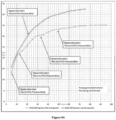
- Fig. 4 illustrates graphical results associated with the multistage pump (100).
- the graphical results include a plot of bearing temperature vs time for the multistage pump (100).
- the multistage pump (100) is a CHTR 4/1 +6 pump with antifriction bearings.
- the pressure P1' in the clearance gap ("Se") is about 24 bars at minimum flow of about 60 m ⁇ 3/hr.
- the throttle valve (104) in the bypass line (106) is operated in steps until the pressure P1' in the clearance gap ("Se") is increased to a pre-determined calculated value of 40 bar. It is evident from Fig. 4 , that the bearing temperature is reduced by 7 degree Celsius, which indicates that the axial load on the bearing of the multistage pump (100) is reduced.
- Fig. 5 illustrates a schematic view of a multistage pump (500) with axial thrust optimization in accordance with another embodiment of the present disclosure.
- the multistage pump (500) includes a bypass system (502) configured for the axial thrust optimization.
- the bypass system (502) includes a throttle bush (504) provided proximally to a clearance gap ("Se"), wherein the throttle bush (504) defines a bypass line (506), such that the clearance gap ("Se") is configured to receive a balancing flow through the bypass line (506) for increasing a pressure P1' in the clearance gap ("Se") for axial thrust optimization.
- the throttle bush (504) includes a flow control device (508) disposed at one end of the bypass line (506) proximal to the clearance gap ("Se"), and an orifice plate (510) disposed at another end of the bypass line (506) opposite to the flow control device (508).
- the flow control device (508) is spring loaded and is configured to operate at part load conditions. In operation, the flow control device (508) operates at the pre-determined calculated value of the pressure Pl', and the flow control device (508) does not operates when the multistage pump (500) is operated at best efficiency/rated flow.
- the orifice plate (510) is configured to decrease discharge pressure and increase the pressure P1' in the clearance gap ("Se") to a pre-determined calculated value.
- the bypass system (102, 502) allows the multistage pump (100, 500) to employ antifriction bearings instead of forced oil lubricated tilting pad bearings, thereby providing a cost-effective solution. Further, overall length of the multistage pump (100, 500) and bearing span is reduced. Further, elimination of costly lube oil plant, corresponding piping and accessories is achieved.
- the pump be equipped with forced oil lubricated plain bearings and tilting pad thrust bearings.
- considerable reduction in the size of tilting pad thrust bearing and lube oil pump/plant may be achieved by using the bypass system (102, 502), as the net thrust load acting on tilting pad bearing is reduced.
Landscapes
- Engineering & Computer Science (AREA)
- Mechanical Engineering (AREA)
- General Engineering & Computer Science (AREA)
- Structures Of Non-Positive Displacement Pumps (AREA)
- Control Of Non-Positive-Displacement Pumps (AREA)
- Jet Pumps And Other Pumps (AREA)
Claims (7)
- Mehrstufige Pumpe (500) mit Axialschuboptimierung, wobei die mehrstufige Pumpe (500) Folgendes umfasst:
ein Umgehungssystem (502), das für die Axialschuboptimierung ausgelegt ist, wobei das Umgehungssystem (502) Folgendes umfasst:
eine Drosselbuchse (504), die proximal zu einem Spielraum ("Se") bereitgestellt ist, wobei die Drosselbuchse (504) eine Umgehungsleitung (506) definiert, sodass der Spielraum ("Se") dazu ausgelegt ist, eine Ausgleichsströmung durch die Umgehungsleitung (506) zum Erhöhen eines Drucks in dem Spielraum ("Se") für eine Axialschuboptimierung aufzunehmen,
dadurch gekennzeichnet, dass
die Drosselbuchse (504) eine Durchflusssteuervorrichtung (508) umfasst, die an einem Ende der Umgehungsleitung (506) proximal zu dem Spielraum ("Se") bereitgestellt ist. - Mehrstufige Pumpe (500) nach Anspruch 1, dadurch gekennzeichnet, dass eine Lochblende (510) an einem anderen Ende der Umgehungsleitung (506) gegenüber der Durchflusssteuervorrichtung (508) angeordnet ist.
- Mehrstufige Pumpe (500) nach Anspruch 1 oder 2, dadurch gekennzeichnet, dass die Durchflusssteuervorrichtung (508) federbelastet ist.
- Mehrstufige Pumpe (500) nach einem der Ansprüche 1 bis 3, dadurch gekennzeichnet, dass die Durchflusssteuervorrichtung (508) dazu ausgelegt ist, unter Teillastbedingungen zu arbeiten.
- Mehrstufige Pumpe (500) nach Anspruch 2, dadurch gekennzeichnet, dass die Lochblende (510) dazu ausgelegt ist, einen Entladedruck zu verringern und den Druck in dem Spielraum ("Se") auf einen vorbestimmten berechneten Wert zu erhöhen.
- Mehrstufige Pumpe (500) nach einem der Ansprüche 1 bis 5, dadurch gekennzeichnet, dass die Durchflusssteuervorrichtung (508) bei dem vorbestimmten berechneten Wert des Drucks arbeitet, und die Durchflusssteuervorrichtung (508) nicht arbeitet, wenn die mehrstufige Pumpe (500) bei einem Durchfluss mit maximalem Wirkungsgrad/Nenndurchfluss betrieben wird.
- Mehrstufige Pumpe (100) nach Anspruch 1, wobei der Druck in dem Spielraum ("Se") 24 bar bei einem Mindestdurchfluss von 60 m^3/h beträgt.
Applications Claiming Priority (2)
| Application Number | Priority Date | Filing Date | Title |
|---|---|---|---|
| IN201821036447 | 2018-09-27 | ||
| PCT/IN2019/050705 WO2020065674A1 (en) | 2018-09-27 | 2019-09-26 | A multistage pump with axial thrust optimization |
Publications (3)
| Publication Number | Publication Date |
|---|---|
| EP3857072A1 EP3857072A1 (de) | 2021-08-04 |
| EP3857072C0 EP3857072C0 (de) | 2024-01-03 |
| EP3857072B1 true EP3857072B1 (de) | 2024-01-03 |
Family
ID=68165686
Family Applications (1)
| Application Number | Title | Priority Date | Filing Date |
|---|---|---|---|
| EP19783735.4A Active EP3857072B1 (de) | 2018-09-27 | 2019-09-26 | Mehrstufige pumpe mit axialschuboptimierung |
Country Status (8)
| Country | Link |
|---|---|
| US (1) | US11549512B2 (de) |
| EP (1) | EP3857072B1 (de) |
| JP (1) | JP7693537B2 (de) |
| KR (1) | KR102771080B1 (de) |
| CN (1) | CN113227583B (de) |
| ES (1) | ES2973344T3 (de) |
| SA (1) | SA521421596B1 (de) |
| WO (1) | WO2020065674A1 (de) |
Family Cites Families (22)
| Publication number | Priority date | Publication date | Assignee | Title |
|---|---|---|---|---|
| US971851A (en) | 1905-11-28 | 1910-10-04 | Ferdinand W Krogh | Centrifugal pump. |
| GB191005848A (en) * | 1909-03-12 | 1910-07-21 | Hans James Schwade | Improvements in or relating to Centrifugal Pumps. |
| GB190916373A (en) * | 1909-07-13 | 1910-07-07 | Emil Schauffelberger | Improvements in and relating to Means for Balancing the End-thrust on the Rotor in Rotary Pumps, Blowers, Compressors and the like. |
| FR478437A (fr) | 1914-04-17 | 1915-12-10 | The United States Light And Heating Company | Perfectionnements aux collecteurs pour machines électriques |
| GB191516373A (en) | 1915-11-20 | 1916-11-02 | Stanley Parsons | Improvements in Hand Operated Trucks for the Lifting and Transport of Goods. |
| DE933849C (de) * | 1952-02-10 | 1955-10-06 | Klein | Einrichtung zum Schutze von Kreiselpumpen mit hydraulischer Achsschubentlastung durch Regelung der in den Zulaufbehaelter rueckgefuehrten Entlastungsfluessigkeitsmenge |
| US3464440A (en) * | 1966-03-18 | 1969-09-02 | Schroeder & Co H | Method and apparatus for protecting a pump from flow rate overloads |
| CH501839A (fr) | 1966-11-12 | 1971-01-15 | Zabrzanska Fabryka Masz Gornic | Pompe dynamique |
| JPS5810195A (ja) * | 1981-07-10 | 1983-01-20 | Hitachi Ltd | 軸推力平衡装置 |
| US4472107A (en) | 1982-08-03 | 1984-09-18 | Union Carbide Corporation | Rotary fluid handling machine having reduced fluid leakage |
| CH669241A5 (de) * | 1985-11-27 | 1989-02-28 | Sulzer Ag | Axialschub-ausgleichsvorrichtung fuer fluessigkeitspumpe. |
| US4740137A (en) * | 1986-11-17 | 1988-04-26 | Dresser Industries, Inc. | Method and apparatus for improving the efficiency of centrifugal pumps |
| US5591016A (en) * | 1994-11-30 | 1997-01-07 | Nikkiso Co., Ltd. | Multistage canned motor pump having a thrust balancing disk |
| US6129507A (en) | 1999-04-30 | 2000-10-10 | Technology Commercialization Corporation | Method and device for reducing axial thrust in rotary machines and a centrifugal pump using same |
| US7108569B2 (en) | 2003-03-19 | 2006-09-19 | Cornell Donald E | Axial flow pump or marine propulsion device |
| JP4352903B2 (ja) * | 2004-01-15 | 2009-10-28 | 株式会社日立プラントテクノロジー | 一軸多段ポンプ |
| CN100455824C (zh) * | 2005-01-30 | 2009-01-28 | 陆雄 | 动态调控用平衡鼓平衡轴向力的多级离心泵轴向力的方法 |
| JP2007085223A (ja) * | 2005-09-21 | 2007-04-05 | Mitsubishi Heavy Ind Ltd | 軸スラストのバランス機構 |
| US8016545B2 (en) * | 2006-06-14 | 2011-09-13 | Fluid Equipment Development Company, Llc | Thrust balancing in a centrifugal pump |
| US20090004032A1 (en) * | 2007-03-29 | 2009-01-01 | Ebara International Corporation | Deswirl mechanisms and roller bearings in an axial thrust equalization mechanism for liquid cryogenic turbomachinery |
| US10178723B2 (en) | 2011-06-03 | 2019-01-08 | Cree, Inc. | Systems and methods for controlling solid state lighting devices and lighting apparatus incorporating such systems and/or methods |
| JP2014074359A (ja) * | 2012-10-04 | 2014-04-24 | Ebara Corp | 多段ポンプ |
-
2019
- 2019-09-26 ES ES19783735T patent/ES2973344T3/es active Active
- 2019-09-26 KR KR1020217012737A patent/KR102771080B1/ko active Active
- 2019-09-26 WO PCT/IN2019/050705 patent/WO2020065674A1/en not_active Ceased
- 2019-09-26 CN CN201980077920.4A patent/CN113227583B/zh active Active
- 2019-09-26 US US17/280,515 patent/US11549512B2/en active Active
- 2019-09-26 EP EP19783735.4A patent/EP3857072B1/de active Active
- 2019-09-26 JP JP2021517382A patent/JP7693537B2/ja active Active
-
2021
- 2021-03-28 SA SA521421596A patent/SA521421596B1/ar unknown
Also Published As
| Publication number | Publication date |
|---|---|
| EP3857072A1 (de) | 2021-08-04 |
| BR112021005957A8 (pt) | 2023-11-21 |
| ES2973344T3 (es) | 2024-06-19 |
| US20220042513A1 (en) | 2022-02-10 |
| EP3857072C0 (de) | 2024-01-03 |
| BR112021005957A2 (pt) | 2021-06-29 |
| KR20210065172A (ko) | 2021-06-03 |
| CN113227583A (zh) | 2021-08-06 |
| JP7693537B2 (ja) | 2025-06-17 |
| KR102771080B1 (ko) | 2025-02-21 |
| CN113227583B (zh) | 2023-08-08 |
| SA521421596B1 (ar) | 2023-01-31 |
| JP2022500592A (ja) | 2022-01-04 |
| US11549512B2 (en) | 2023-01-10 |
| WO2020065674A1 (en) | 2020-04-02 |
Similar Documents
| Publication | Publication Date | Title |
|---|---|---|
| EP0102334B1 (de) | Rotierende, mit einem Fluid arbeitende Maschine mit verringertem Fluid-Leckverlust | |
| US5267452A (en) | Back pressure valve | |
| US6309174B1 (en) | Thrust bearing for multistage centrifugal pumps | |
| US5529464A (en) | Cryogenic turbopump | |
| EP0094075B1 (de) | Lager für die Rotorwelle einer vertikalen Motorpumpe | |
| US2927536A (en) | Variable capacity pump | |
| CA2081327A1 (en) | Control system for regulating the axial loading of a rotor of a fluid machine | |
| EP3896288A1 (de) | Zentrifugalpumpe zum fördern eines fluids | |
| US4806075A (en) | Turbomolecular pump with improved bearing assembly | |
| CZ20021454A3 (cs) | Zařízení pro kompenzaci axiálního posunu u turbostrojů | |
| EP3118460B1 (de) | Turbomaschine | |
| EP3857072B1 (de) | Mehrstufige pumpe mit axialschuboptimierung | |
| CA3125001C (en) | A pump with a bearing lubrication system | |
| US11085457B2 (en) | Thrust bearing system and method for operating the same | |
| GB2493737A (en) | Turbo-machine automatic thrust balancing | |
| EP4030065B1 (de) | Rotationspumpe mit axialschub-entlastungskolben und regelung einer leckageströmung | |
| US3692373A (en) | Slipper bearing lubrication and seal | |
| Mel'nik | Modern Trends in the Design of Slide Bearing Supports for Centrifugal Pumps. | |
| BR112021005957B1 (pt) | Bomba de múltiplos estágios | |
| CA3056662A1 (en) | Thrust bearing system and method for operating the same | |
| CS218215B1 (cs) | Hydraulické snímací ústrojí |
Legal Events
| Date | Code | Title | Description |
|---|---|---|---|
| STAA | Information on the status of an ep patent application or granted ep patent |
Free format text: STATUS: UNKNOWN |
|
| STAA | Information on the status of an ep patent application or granted ep patent |
Free format text: STATUS: THE INTERNATIONAL PUBLICATION HAS BEEN MADE |
|
| PUAI | Public reference made under article 153(3) epc to a published international application that has entered the european phase |
Free format text: ORIGINAL CODE: 0009012 |
|
| STAA | Information on the status of an ep patent application or granted ep patent |
Free format text: STATUS: REQUEST FOR EXAMINATION WAS MADE |
|
| 17P | Request for examination filed |
Effective date: 20210420 |
|
| AK | Designated contracting states |
Kind code of ref document: A1 Designated state(s): AL AT BE BG CH CY CZ DE DK EE ES FI FR GB GR HR HU IE IS IT LI LT LU LV MC MK MT NL NO PL PT RO RS SE SI SK SM TR |
|
| DAV | Request for validation of the european patent (deleted) | ||
| DAX | Request for extension of the european patent (deleted) | ||
| GRAP | Despatch of communication of intention to grant a patent |
Free format text: ORIGINAL CODE: EPIDOSNIGR1 |
|
| STAA | Information on the status of an ep patent application or granted ep patent |
Free format text: STATUS: GRANT OF PATENT IS INTENDED |
|
| INTG | Intention to grant announced |
Effective date: 20230320 |
|
| GRAS | Grant fee paid |
Free format text: ORIGINAL CODE: EPIDOSNIGR3 |
|
| GRAJ | Information related to disapproval of communication of intention to grant by the applicant or resumption of examination proceedings by the epo deleted |
Free format text: ORIGINAL CODE: EPIDOSDIGR1 |
|
| GRAL | Information related to payment of fee for publishing/printing deleted |
Free format text: ORIGINAL CODE: EPIDOSDIGR3 |
|
| STAA | Information on the status of an ep patent application or granted ep patent |
Free format text: STATUS: REQUEST FOR EXAMINATION WAS MADE |
|
| GRAP | Despatch of communication of intention to grant a patent |
Free format text: ORIGINAL CODE: EPIDOSNIGR1 |
|
| STAA | Information on the status of an ep patent application or granted ep patent |
Free format text: STATUS: GRANT OF PATENT IS INTENDED |
|
| INTC | Intention to grant announced (deleted) | ||
| INTG | Intention to grant announced |
Effective date: 20230802 |
|
| GRAA | (expected) grant |
Free format text: ORIGINAL CODE: 0009210 |
|
| STAA | Information on the status of an ep patent application or granted ep patent |
Free format text: STATUS: THE PATENT HAS BEEN GRANTED |
|
| AK | Designated contracting states |
Kind code of ref document: B1 Designated state(s): AL AT BE BG CH CY CZ DE DK EE ES FI FR GB GR HR HU IE IS IT LI LT LU LV MC MK MT NL NO PL PT RO RS SE SI SK SM TR |
|
| REG | Reference to a national code |
Ref country code: GB Ref legal event code: FG4D |
|
| REG | Reference to a national code |
Ref country code: DE Ref legal event code: R096 Ref document number: 602019044504 Country of ref document: DE |
|
| REG | Reference to a national code |
Ref country code: CH Ref legal event code: EP |
|
| REG | Reference to a national code |
Ref country code: IE Ref legal event code: FG4D |
|
| U01 | Request for unitary effect filed |
Effective date: 20240126 |
|
| U07 | Unitary effect registered |
Designated state(s): AT BE BG DE DK EE FI FR IT LT LU LV MT NL PT SE SI Effective date: 20240207 |
|
| REG | Reference to a national code |
Ref country code: ES Ref legal event code: FG2A Ref document number: 2973344 Country of ref document: ES Kind code of ref document: T3 Effective date: 20240619 |
|
| PG25 | Lapsed in a contracting state [announced via postgrant information from national office to epo] |
Ref country code: IS Free format text: LAPSE BECAUSE OF FAILURE TO SUBMIT A TRANSLATION OF THE DESCRIPTION OR TO PAY THE FEE WITHIN THE PRESCRIBED TIME-LIMIT Effective date: 20240503 |
|
| PG25 | Lapsed in a contracting state [announced via postgrant information from national office to epo] |
Ref country code: GR Free format text: LAPSE BECAUSE OF FAILURE TO SUBMIT A TRANSLATION OF THE DESCRIPTION OR TO PAY THE FEE WITHIN THE PRESCRIBED TIME-LIMIT Effective date: 20240404 |
|
| PG25 | Lapsed in a contracting state [announced via postgrant information from national office to epo] |
Ref country code: HR Free format text: LAPSE BECAUSE OF FAILURE TO SUBMIT A TRANSLATION OF THE DESCRIPTION OR TO PAY THE FEE WITHIN THE PRESCRIBED TIME-LIMIT Effective date: 20240103 Ref country code: RS Free format text: LAPSE BECAUSE OF FAILURE TO SUBMIT A TRANSLATION OF THE DESCRIPTION OR TO PAY THE FEE WITHIN THE PRESCRIBED TIME-LIMIT Effective date: 20240403 |
|
| PG25 | Lapsed in a contracting state [announced via postgrant information from national office to epo] |
Ref country code: CZ Free format text: LAPSE BECAUSE OF FAILURE TO SUBMIT A TRANSLATION OF THE DESCRIPTION OR TO PAY THE FEE WITHIN THE PRESCRIBED TIME-LIMIT Effective date: 20240103 |
|
| PG25 | Lapsed in a contracting state [announced via postgrant information from national office to epo] |
Ref country code: RS Free format text: LAPSE BECAUSE OF FAILURE TO SUBMIT A TRANSLATION OF THE DESCRIPTION OR TO PAY THE FEE WITHIN THE PRESCRIBED TIME-LIMIT Effective date: 20240403 Ref country code: IS Free format text: LAPSE BECAUSE OF FAILURE TO SUBMIT A TRANSLATION OF THE DESCRIPTION OR TO PAY THE FEE WITHIN THE PRESCRIBED TIME-LIMIT Effective date: 20240503 Ref country code: HR Free format text: LAPSE BECAUSE OF FAILURE TO SUBMIT A TRANSLATION OF THE DESCRIPTION OR TO PAY THE FEE WITHIN THE PRESCRIBED TIME-LIMIT Effective date: 20240103 Ref country code: GR Free format text: LAPSE BECAUSE OF FAILURE TO SUBMIT A TRANSLATION OF THE DESCRIPTION OR TO PAY THE FEE WITHIN THE PRESCRIBED TIME-LIMIT Effective date: 20240404 Ref country code: CZ Free format text: LAPSE BECAUSE OF FAILURE TO SUBMIT A TRANSLATION OF THE DESCRIPTION OR TO PAY THE FEE WITHIN THE PRESCRIBED TIME-LIMIT Effective date: 20240103 |
|
| PG25 | Lapsed in a contracting state [announced via postgrant information from national office to epo] |
Ref country code: PL Free format text: LAPSE BECAUSE OF FAILURE TO SUBMIT A TRANSLATION OF THE DESCRIPTION OR TO PAY THE FEE WITHIN THE PRESCRIBED TIME-LIMIT Effective date: 20240103 |
|
| PG25 | Lapsed in a contracting state [announced via postgrant information from national office to epo] |
Ref country code: PL Free format text: LAPSE BECAUSE OF FAILURE TO SUBMIT A TRANSLATION OF THE DESCRIPTION OR TO PAY THE FEE WITHIN THE PRESCRIBED TIME-LIMIT Effective date: 20240103 |
|
| REG | Reference to a national code |
Ref country code: DE Ref legal event code: R097 Ref document number: 602019044504 Country of ref document: DE |
|
| PG25 | Lapsed in a contracting state [announced via postgrant information from national office to epo] |
Ref country code: SM Free format text: LAPSE BECAUSE OF FAILURE TO SUBMIT A TRANSLATION OF THE DESCRIPTION OR TO PAY THE FEE WITHIN THE PRESCRIBED TIME-LIMIT Effective date: 20240103 |
|
| PG25 | Lapsed in a contracting state [announced via postgrant information from national office to epo] |
Ref country code: SK Free format text: LAPSE BECAUSE OF FAILURE TO SUBMIT A TRANSLATION OF THE DESCRIPTION OR TO PAY THE FEE WITHIN THE PRESCRIBED TIME-LIMIT Effective date: 20240103 |
|
| U20 | Renewal fee for the european patent with unitary effect paid |
Year of fee payment: 6 Effective date: 20240924 |
|
| PG25 | Lapsed in a contracting state [announced via postgrant information from national office to epo] |
Ref country code: SM Free format text: LAPSE BECAUSE OF FAILURE TO SUBMIT A TRANSLATION OF THE DESCRIPTION OR TO PAY THE FEE WITHIN THE PRESCRIBED TIME-LIMIT Effective date: 20240103 Ref country code: SK Free format text: LAPSE BECAUSE OF FAILURE TO SUBMIT A TRANSLATION OF THE DESCRIPTION OR TO PAY THE FEE WITHIN THE PRESCRIBED TIME-LIMIT Effective date: 20240103 Ref country code: RO Free format text: LAPSE BECAUSE OF FAILURE TO SUBMIT A TRANSLATION OF THE DESCRIPTION OR TO PAY THE FEE WITHIN THE PRESCRIBED TIME-LIMIT Effective date: 20240103 |
|
| PGFP | Annual fee paid to national office [announced via postgrant information from national office to epo] |
Ref country code: NO Payment date: 20240920 Year of fee payment: 6 |
|
| PLBE | No opposition filed within time limit |
Free format text: ORIGINAL CODE: 0009261 |
|
| STAA | Information on the status of an ep patent application or granted ep patent |
Free format text: STATUS: NO OPPOSITION FILED WITHIN TIME LIMIT |
|
| 26N | No opposition filed |
Effective date: 20241007 |
|
| PGFP | Annual fee paid to national office [announced via postgrant information from national office to epo] |
Ref country code: ES Payment date: 20241001 Year of fee payment: 6 |
|
| PGFP | Annual fee paid to national office [announced via postgrant information from national office to epo] |
Ref country code: CH Payment date: 20241001 Year of fee payment: 6 |
|
| PG25 | Lapsed in a contracting state [announced via postgrant information from national office to epo] |
Ref country code: MC Free format text: LAPSE BECAUSE OF FAILURE TO SUBMIT A TRANSLATION OF THE DESCRIPTION OR TO PAY THE FEE WITHIN THE PRESCRIBED TIME-LIMIT Effective date: 20240103 |
|
| PG25 | Lapsed in a contracting state [announced via postgrant information from national office to epo] |
Ref country code: IE Free format text: LAPSE BECAUSE OF NON-PAYMENT OF DUE FEES Effective date: 20240926 |
|
| REG | Reference to a national code |
Ref country code: CH Ref legal event code: U11 Free format text: ST27 STATUS EVENT CODE: U-0-0-U10-U11 (AS PROVIDED BY THE NATIONAL OFFICE) Effective date: 20251001 |
|
| PGFP | Annual fee paid to national office [announced via postgrant information from national office to epo] |
Ref country code: GB Payment date: 20250927 Year of fee payment: 7 |
|
| U20 | Renewal fee for the european patent with unitary effect paid |
Year of fee payment: 7 Effective date: 20250926 |