EP1228823A1 - Stanzeinrichtung für die Stanzung von Druckplatten und mit einer Stanzeinrichtung ausgerüsteter Druckplattenbelichter - Google Patents
Stanzeinrichtung für die Stanzung von Druckplatten und mit einer Stanzeinrichtung ausgerüsteter Druckplattenbelichter Download PDFInfo
- Publication number
- EP1228823A1 EP1228823A1 EP01126174A EP01126174A EP1228823A1 EP 1228823 A1 EP1228823 A1 EP 1228823A1 EP 01126174 A EP01126174 A EP 01126174A EP 01126174 A EP01126174 A EP 01126174A EP 1228823 A1 EP1228823 A1 EP 1228823A1
- Authority
- EP
- European Patent Office
- Prior art keywords
- punching
- punch
- pressure plate
- punching device
- printing
- Prior art date
- Legal status (The legal status is an assumption and is not a legal conclusion. Google has not performed a legal analysis and makes no representation as to the accuracy of the status listed.)
- Granted
Links
- 238000004080 punching Methods 0.000 title claims abstract description 96
- 238000007639 printing Methods 0.000 title claims abstract description 61
- 239000002699 waste material Substances 0.000 claims description 3
- 238000000034 method Methods 0.000 description 3
- 238000011161 development Methods 0.000 description 2
- 230000018109 developmental process Effects 0.000 description 2
- 208000036829 Device dislocation Diseases 0.000 description 1
- 238000004519 manufacturing process Methods 0.000 description 1
- 238000007645 offset printing Methods 0.000 description 1
- 239000007787 solid Substances 0.000 description 1
Images

Classifications
-
- B—PERFORMING OPERATIONS; TRANSPORTING
- B41—PRINTING; LINING MACHINES; TYPEWRITERS; STAMPS
- B41F—PRINTING MACHINES OR PRESSES
- B41F13/00—Common details of rotary presses or machines
-
- B—PERFORMING OPERATIONS; TRANSPORTING
- B21—MECHANICAL METAL-WORKING WITHOUT ESSENTIALLY REMOVING MATERIAL; PUNCHING METAL
- B21D—WORKING OR PROCESSING OF SHEET METAL OR METAL TUBES, RODS OR PROFILES WITHOUT ESSENTIALLY REMOVING MATERIAL; PUNCHING METAL
- B21D28/00—Shaping by press-cutting; Perforating
- B21D28/24—Perforating, i.e. punching holes
- B21D28/26—Perforating, i.e. punching holes in sheets or flat parts
-
- B—PERFORMING OPERATIONS; TRANSPORTING
- B21—MECHANICAL METAL-WORKING WITHOUT ESSENTIALLY REMOVING MATERIAL; PUNCHING METAL
- B21D—WORKING OR PROCESSING OF SHEET METAL OR METAL TUBES, RODS OR PROFILES WITHOUT ESSENTIALLY REMOVING MATERIAL; PUNCHING METAL
- B21D28/00—Shaping by press-cutting; Perforating
- B21D28/24—Perforating, i.e. punching holes
- B21D28/34—Perforating tools; Die holders
- B21D28/343—Draw punches
Definitions
- the invention relates to a punching device for punching, in particular the Register punching, of printing plates, in particular for arrangement in the area of a Printing platesetter, preferably in the edge region of a trough of an inner drum platesetter, comprising a punch that is transverse or more or less perpendicular to a positioning surface for the printing plate to be punched is guided movably and drivably and with a punching tool for overlapping the edge of the pressure plate to be punched.
- the invention further relates to a printing platesetter, preferably one Inner drum printing platesetter with at least one punching device of the aforementioned type is equipped.
- a punching device of the type mentioned above is known from EP 0 759 851 B1 known.
- Such punching devices are used for punching recesses in printing plates, especially in offset printing plates, with the help of which the printing plates are in front fits the print, especially for a harmonious multi-color print register accurate, clamped in the printing press, preferably on one Printing plate cylinder can be clamped.
- This is done with the punched recesses especially the dimensional reference of the printing area of the Printing plate, that is the area of the previously exposed in the printing platesetter Printing plate, made for the printing form cylinder.
- Such a die cut could also outside the platesetter in a separate punching device take place, which in part actually happens, but to achieve an accurate Dimension of the punched recesses to the exposed area better and more accurately should be done in the platesetter itself and mostly now is also made.
- Such punching devices are therefore preferred arranged in platesetters themselves, with inner drum, flat bed and Outer drum platesetters come into consideration. In the cited publication is referred to an inner drum platesetter, which too is preferred in the present invention.
- the printing plate to be exposed is in the inside, namely in the trough, introduced into an approximately semi-cylindrical drum and there usually by negative air pressure (vacuum) in the exposure position fixed.
- the exposure is then usually carried out with laser light, this low energy, e.g. B. infrared, which can be a daylight-sensitive Exposure like a film that needs to be developed and fixed leads or the laser light can be of higher energy, e.g. B. ultraviolet, resulting in a daylight-insensitive, thermal exposure leads.
- the exposure device is essentially in both methods Area of the cylinder axis of the inner drum.
- the pressure plate must Exposure is placed in the well and after exposure from the well again are removed, which is also used for the interior of the imagesetter drum got to.
- the well-known punching device is used on the and outlet side for the pressure plate opposite edge of the trough arranged.
- the die cut may not work with the intended one Punching device can be made in the platesetter, but must be in a separate, external punching device, possibly with the printing press operator, be made. Nevertheless, at least one should already do so dimensional positioning of the exposed surface of the printing plate to the edge of the Pressure plate in the platesetter itself to make an exact external punching prepare and ensure, without this in turn the handling the printing plate in the platesetter is more difficult and time consuming.
- the invention is therefore based on the object of a punching device at the beginning mentioned genus with a view to easier handling of the To further develop the printing plate in the platesetter.
- a punching device which as Pull punch is formed, in which the punching tool is completely through
- the pressure plate to be punched can be pulled through and in or below the positioning surface the pressure plate, which can also be a tangential surface to a trough, retractable is.
- “Below the positioning surface” is not necessarily perpendicular To understand direction, but in the sense of "on the exposure side of the Printing plate facing away from the back of the printing plate ".
- the punch in the positioning surface of the printing plate is retractable, is particularly advantageous in this position of the punch the pressure plate can also be moved over the area of the punching device without the punching device interferes with this sequence of movements. This makes handling the printing plate in the platesetter easier.
- the punching device can namely in the path of movement of the pressure plate, for. B. on the entry and exit side for the printing plate.
- trained platesetters also claim independent protection.
- the printing plate can be recessed Punching device to be moved and initially in the exposure position be exposed.
- the exposed printing plate is placed on the meanwhile brought into functional position punching device moved, especially if this is necessary with a relatively small format printing plate, but with advantage in the direction in which the printing plate is to be removed from the platesetter anyway must be moved.
- punching that's through the pressure plate solid punch sunk again, so that the pressure plate then out from the platesetter, again over the punching device can.
- a semi-automatic or fully automatic printing plate input and - Output can be controlled and controlled considerably easier and cheaper perform faster, with more precision.
- the punch comprises the punching device a shaft and a punch head with a punch protruding from the shaft. This not only enables the edge of the printing plate to be overlapped the punching tool for punching but the different sections of the Stamping stamps can also be according to preferred developments of the invention various positioning tasks for the edge of the printing plate in advantageous Way take over.
- the extended shaft of the punch can be used to punch the printing plate serve as a stop for the edge of the pressure plate, so that the overlap depth of the punching tool over the edge of the printing plate precisely and reproducibly is set.
- the invention of the slightly extended punch head as a stop serve to align the pressure plate, especially for dimensional adjustment the area of the printing plate to be exposed to the edge of the printing plate in With regard to the later punching.
- the punching tool With its movement into its recess, the punching tool takes away the punching waste with, which according to a development of the invention in the sinking by a Failure chute can be ejected.
- platesetters are preferred several punching devices arranged at a distance from one another are provided.
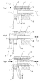
- Fig. 1 shows in section an embodiment of a punching device according to the invention.
- the punching device comprises a punch 1 with a shaft 2 and a punch head 3, which a punch 4, namely a punch finger or a punching needle.
- the shaft 2 is in a guide 5 one Punching head 6, in which the punch head can be lowered.
- the stamp 1 can be moved out of the punching head 6 in the direction of the double arrow 7 and retractable. For this purpose he is in the embodiment shown with a Spindle 8 driven. Other drives can also be considered.
- Fig. 2 shows the punching device according to Fig.1, also in section, with another Position of the punch 1.
- the punch 1 is so far from its Retracted that the punch 4 in the functional position for a punching process.
- the pressure plate 10 to be punched is already corresponding positioned by abutting the shaft 2 of the punch 1 located. For this purpose, the pressure plate was previously in the direction of arrow 12 against the Shaft 2 of the punch 1 shifted.
- FIG. 3 shows the punching device, again in section, after the punching process, So after the punch head 3 with the production of a recess 13 through the Pressure plate 10 has been pulled and sunk again in the punch head 6 is.
- the punching waste 14 from the recess 13 is through a chute 15 ejected from the punching head 6.
- the shaft 2 of the punch 1 also has a recess 16 as an alternative Stop area for the pressure plate 10 can act as related will be explained in more detail with the following figures.
- FIGS 4 to 6 show in section the punching device according to the previous ones Figures with different functional positions of the punch 1, wherein The same components are designated with the same reference numbers as in the previous figures.
- This positioning of the pressure plate for the accurate punching of a recess 13 is correct for some printing presses.
- the stop of the pressure plate 10 on the shaft 2 defines the overlap depth of the punch 4 over the edge the pressure plate 10 and thus the depth of the recess 13.
- the pressure plate 10 strikes in the recess 16 on the shaft 2, for which the The punch 1 is extended a little less from the punch head 6 than in of Fig. 4. This overlaps the punch 4 over the edge of the Pressure plate 10 larger and the recess 13 deeper, what for some others Printing presses is correct. You can change the depth of the punch Designate X or Y over the edge of the printing plate in FIGS. 4 and 6.
- the punch 1 is moved further into the punch head 6 than in Figure 6, however, the punch head 3 still protrudes from the punch head 6 or so that it can serve as a stop for the pressure plate 10, as shown a measure of the distance of the surface to be exposed from the edge of the Find and set pressure plate 10, in the event that for a rarer Printing machine no punching can be made with the punch 4 should.
Landscapes
- Engineering & Computer Science (AREA)
- Mechanical Engineering (AREA)
- Perforating, Stamping-Out Or Severing By Means Other Than Cutting (AREA)
- Exposure And Positioning Against Photoresist Photosensitive Materials (AREA)
- Manufacture Or Reproduction Of Printing Formes (AREA)
- Supply, Installation And Extraction Of Printed Sheets Or Plates (AREA)
Abstract
Description
- Fig. 1
- eine Schnittansicht einer erfindungsgemäßen Stanzeinrichtung mit daran vorbeilaufender Druckplatte,
- Fig. 2
- die Stanzeinrichtung gemäß Fig. 1 im Schnitt mit anschlagender Druckplatte,
- Fig. 3
- die Stanzeinrichtung gemäß den Fig. 1 und 2 nach einer Stanzung,
- Fig. 4
- eine Druckplatte im Anschlag am Schaft eines Stanzstempels einer Stanzeinrichtung gemäß den Figuren 1 bis 3,
- Fig. 5
- eine Druckplatte im Anschlag am Stanzstempelkopf eines Stanzstempels gemäß Fig. 4 und
- Fig. 6
- eine Druckplatte im Anschlag in einem Rezeß des Schaftes gemäß Fig. 4.
Claims (10)
- Stanzeinrichtung für die Stanzung, insbesondere Registerstanzung, von Druckplatten, insbesondere zur Anordnung im Bereich eines Druckplattenbelichters, vorzugsweise im Randbereich einer Mulde eines Innentrommel-Plattenbelichters, umfassend einen Stanzstempel, der quer oder mehr oder weniger senkrecht zu einer Positionierfläche für die zu stanzende Druckplatte beweglich und antreibbar geführt ist und mit einem Stanzwerkzeug zum Übergriff des Randes der zu stanzenden Druckplatte ausgerüstet ist dadurch gekennzeichnet, daß die Stanzeinrichtung als Durchzugsstanze ausgebildet ist, bei der das Stanzwerkzeug (4) vollständig durch die zu stanzende Druckplatte (10) durchziehbar und in oder unterhalb deren Positionierfläche (9) versenkbar ist.
- Stanzeinrichtung nach Anspruch 1, dadurch gekennzeichnet, daß der Stanzstempel (1) einen Schaft (2) und am freien Ende des Schaftes (2) einen Stanzstempelkopf (3), der das vom Schaft (2) abragende Stanzwerkzeug (4) umfaßt, aufweist.
- Stanzeinrichtung nach Anspruch 2, dadurch gekennzeichnet, daß der Stanzstempelkopf (3) als Anschlag für die zu positionierende Druckplatte (10) vorgesehen ist und daß für den Stanzstempel (1) eine Ausfahrstellung aus seiner Versenkung vorgesehen ist, bei der sich der Stanzstempelkopf (3) schon über die Positionierfläche (9) der Druckplatte (10) erhebt, das Stanzwerkzeug (4) aber noch keine Funktionsstellung innehat.
- Stanzeinrichtung nach Anspruch 2 oder 3, dadurch gekennzeichnet, daß der Schaft (2) als Anschlag für die zu positionierende Druckplatte (10) vorgesehen ist und dazu für den Stanzstempel (1) eine Ausfahrstellung aus seiner Versenkung vorgesehen ist, bei der sich das Stanzwerkzeug (4) in Funktionsstellung über der Positionierfläche (9) der Druckplatte (10) erhebt.
- Stanzeinrichtung nach Anspruch 4, dadurch gekennzeichnet, daß der Schaft (2) wenigstens zwei Anschlagpositionen für die zu positionierende Druckplatte (10) bietet, bei denen der Übergriff des Stanzwerkzeuges (4) über den Rand der Druckplatte (10) unterschiedlich groß ist, und daß mehrere, mit den Anschlagpositionen des Schaftes (2) in der Weise korrelierende Stellungen des Stanzstempels (1) vorgesehen sind, daß jeweils eine ausgewählte der Anschlagpositionen des Schaftes (2) in der Positionierfläche (9) der Druckplatte (10) bereitgestellt ist.
- Stanzeinrichtung nach einem der vorhergehenden Ansprüche, gekenn
- zeichnet durch einen Ausfallschacht (15) für den Stanzabfall (14).
- Druckplattenbelichter, vorzugsweise Innentrommel-Druckplattenbelichter, der mit wenigstens einer als Durchzugsstanze nach einem oder mehreren der vorhergehenden Ansprüche ausgebildeten Stanzeinrichtung ausgerüstet ist, dadurch gekennzeichnet, daß die Stanzeinrichtung innerhalb des Bewegungsweges der zu belichtenden Druckplatte (10) angeordnet ist.
- Druckplattenbelichter nach Anspruch 7, dadurch gekennzeichnet, daß die Stanzeinrichtung an der Eintrittsseite und/oder der Austrittsseite für die Druckplatte (10) angeordnet ist.
- Druckplattenbelichter nach Anspruch 7 oder 8, dadurch gekennzeichnet, daß mehrere Stanzeinrichtungen quer zum Bewegungsweg der Druckplatte (10) in einem Abstand zueinander angeordnet sind.
Applications Claiming Priority (2)
| Application Number | Priority Date | Filing Date | Title |
|---|---|---|---|
| DE10104417A DE10104417A1 (de) | 2001-02-01 | 2001-02-01 | Stanzeinrichtung für die Stanzung von Druckplatten und mit einer Stanzeinrichtung ausgerüsteter Druckplatenbelichter |
| DE10104417 | 2001-02-01 |
Publications (2)
| Publication Number | Publication Date |
|---|---|
| EP1228823A1 true EP1228823A1 (de) | 2002-08-07 |
| EP1228823B1 EP1228823B1 (de) | 2004-08-25 |
Family
ID=7672414
Family Applications (1)
| Application Number | Title | Priority Date | Filing Date |
|---|---|---|---|
| EP01126174A Expired - Lifetime EP1228823B1 (de) | 2001-02-01 | 2001-11-05 | Stanzeinrichtung für die Stanzung von Druckplatten und mit einer Stanzeinrichtung ausgerüsteter Druckplattenbelichter |
Country Status (4)
| Country | Link |
|---|---|
| US (1) | US20020059873A1 (de) |
| EP (1) | EP1228823B1 (de) |
| JP (1) | JP3829096B2 (de) |
| DE (2) | DE10104417A1 (de) |
Families Citing this family (1)
| Publication number | Priority date | Publication date | Assignee | Title |
|---|---|---|---|---|
| US7111482B1 (en) * | 2005-09-13 | 2006-09-26 | Gm Global Technology Operations, Inc. | Punch assembly for hydroforming die |
Citations (1)
| Publication number | Priority date | Publication date | Assignee | Title |
|---|---|---|---|---|
| JP2000056482A (ja) * | 1998-08-04 | 2000-02-25 | Dainippon Screen Mfg Co Ltd | 描画装置 |
Family Cites Families (2)
| Publication number | Priority date | Publication date | Assignee | Title |
|---|---|---|---|---|
| JP2928078B2 (ja) * | 1994-02-10 | 1999-07-28 | 大日本スクリーン製造株式会社 | 円筒内面走査装置に於ける穿孔装置 |
| DE19507870A1 (de) * | 1995-03-08 | 1996-09-12 | Hell Ag Linotype | Stanzmodul für Druckplattenbelichter |
-
2001
- 2001-02-01 DE DE10104417A patent/DE10104417A1/de not_active Withdrawn
- 2001-11-05 EP EP01126174A patent/EP1228823B1/de not_active Expired - Lifetime
- 2001-11-05 DE DE50103390T patent/DE50103390D1/de not_active Expired - Lifetime
-
2002
- 2002-01-31 JP JP2002023388A patent/JP3829096B2/ja not_active Expired - Fee Related
- 2002-02-01 US US10/062,059 patent/US20020059873A1/en not_active Abandoned
Patent Citations (1)
| Publication number | Priority date | Publication date | Assignee | Title |
|---|---|---|---|---|
| JP2000056482A (ja) * | 1998-08-04 | 2000-02-25 | Dainippon Screen Mfg Co Ltd | 描画装置 |
Non-Patent Citations (1)
| Title |
|---|
| PATENT ABSTRACTS OF JAPAN vol. 2000, no. 05 14 September 2000 (2000-09-14) * |
Also Published As
| Publication number | Publication date |
|---|---|
| EP1228823B1 (de) | 2004-08-25 |
| JP3829096B2 (ja) | 2006-10-04 |
| DE10104417A1 (de) | 2002-08-08 |
| US20020059873A1 (en) | 2002-05-23 |
| DE50103390D1 (de) | 2004-09-30 |
| JP2002307658A (ja) | 2002-10-23 |
Similar Documents
| Publication | Publication Date | Title |
|---|---|---|
| EP1196269B1 (de) | Vorrichtung zum stanzen eines stapels aus blättrigem gut | |
| DE69330244T2 (de) | Perforator für Metallplatten | |
| DE3789847T2 (de) | Vorrichtung zum Zuführen und Überwachen von Streifen. | |
| EP2392459B1 (de) | Verfahren und Vorrichtung zur Registersteuerung einer Druckmaschine | |
| EP0091714A1 (de) | Verfahren und Vorrichtung zur Herstellung druckfrischer, numerierter und auf Format geschnittener Wertscheine | |
| DE19643163A1 (de) | Werkzeugwechselvorrichtung für eine Umformpresse sowie Umformpressen-Werkzeugwechselvorrichtungs-Anordnung | |
| DE19516368C2 (de) | Verfahren und Vorrichtung zur Anpassung der Lage von Druckplatten an die Verformung des zu bedruckenden Papieres | |
| CH655903A5 (de) | Verfahren und vorrichtung zum perforieren, stanzen oder rillen von papier und karton in rotationsdruckmaschinen. | |
| DE3318144C2 (de) | Vorrichtung zum Einrichten von Matrizen für eine Stanztiegelpresse | |
| DE2853901C2 (de) | Eindruckvorrichtung für eine Druckmaschine, insbesondere Rotationsdruckmaschine | |
| EP1753622B1 (de) | Verfahren zur herstellung einer druckform und zum zuführen derselben an einen formzylinder einer druckmaschine | |
| DE2306011A1 (de) | Vorrichtung zur bearbeitung von druckplatten bzw. -formen mit einer duennen metallblechplatte als schichttraeger | |
| CH689275A5 (de) | Vorrichtung und Verfahren zum Stanzen eines Stapels. | |
| EP1228823B1 (de) | Stanzeinrichtung für die Stanzung von Druckplatten und mit einer Stanzeinrichtung ausgerüsteter Druckplattenbelichter | |
| DE9316230U1 (de) | Vorrichtung zum passergerechten Positionieren eines Schneidbleches auf einem Schneidzylinder, vorzugsweise in Rotationsdruckmaschinen | |
| WO2015001126A1 (de) | Verfahren und vorrichtung zum gegenseitigen anstellen von zwei zylindern in einer druckmaschine | |
| EP2762432B1 (de) | Überwachungsverfahren zur Kollisionsvermeidung einer Stanzmaschine mit Bremsbürste | |
| EP3749495A1 (de) | Ausbesserungsvorrichtung, sowie verfahren zum ausbessern einer fehlstelle in einem holzwerkstück | |
| DE4313871C2 (de) | Verfahren und Vorrichtung zum Herstellen von Dosenrümpfen aus kunststoffbeschichtetem Blech | |
| DE3307411A1 (de) | Verfahren und vorrichtung zum erkennen von kennzeichnungsmarken auf einer materialbahn | |
| DE19539453A1 (de) | Paßsystem zum Ausrichten von Druckplatten für Offset-Druckmaschinen | |
| DE4332803A1 (de) | Vorrichtung zum automatischen Zuführen von Druckplatten zum Plattenzylinder einer Druckmaschine | |
| DE4221482C2 (de) | Verfahren zur Lagekontrolle eines Druckbildes auf einer Druckform | |
| DE10256236A1 (de) | Druckformladevorrichtung | |
| DE19519386C1 (de) | Vorrichtung zum Einprägen von Abstandssicken |
Legal Events
| Date | Code | Title | Description |
|---|---|---|---|
| PUAI | Public reference made under article 153(3) epc to a published international application that has entered the european phase |
Free format text: ORIGINAL CODE: 0009012 |
|
| AK | Designated contracting states |
Kind code of ref document: A1 Designated state(s): AT BE CH CY DE DK ES FI FR GB GR IE IT LI LU MC NL PT SE TR |
|
| AX | Request for extension of the european patent |
Free format text: AL;LT;LV;MK;RO;SI |
|
| 17P | Request for examination filed |
Effective date: 20030207 |
|
| AKX | Designation fees paid |
Designated state(s): BE DE FR GB |
|
| GRAP | Despatch of communication of intention to grant a patent |
Free format text: ORIGINAL CODE: EPIDOSNIGR1 |
|
| GRAS | Grant fee paid |
Free format text: ORIGINAL CODE: EPIDOSNIGR3 |
|
| GRAA | (expected) grant |
Free format text: ORIGINAL CODE: 0009210 |
|
| AK | Designated contracting states |
Kind code of ref document: B1 Designated state(s): BE DE FR GB |
|
| REG | Reference to a national code |
Ref country code: GB Ref legal event code: FG4D Free format text: NOT ENGLISH |
|
| REG | Reference to a national code |
Ref country code: IE Ref legal event code: FG4D Free format text: GERMAN |
|
| REF | Corresponds to: |
Ref document number: 50103390 Country of ref document: DE Date of ref document: 20040930 Kind code of ref document: P |
|
| GBT | Gb: translation of ep patent filed (gb section 77(6)(a)/1977) |
Effective date: 20040922 |
|
| REG | Reference to a national code |
Ref country code: IE Ref legal event code: FD4D |
|
| ET | Fr: translation filed | ||
| PLBE | No opposition filed within time limit |
Free format text: ORIGINAL CODE: 0009261 |
|
| STAA | Information on the status of an ep patent application or granted ep patent |
Free format text: STATUS: NO OPPOSITION FILED WITHIN TIME LIMIT |
|
| 26N | No opposition filed |
Effective date: 20050526 |
|
| PGFP | Annual fee paid to national office [announced via postgrant information from national office to epo] |
Ref country code: DE Payment date: 20121130 Year of fee payment: 12 |
|
| PGFP | Annual fee paid to national office [announced via postgrant information from national office to epo] |
Ref country code: BE Payment date: 20121129 Year of fee payment: 12 Ref country code: GB Payment date: 20121126 Year of fee payment: 12 |
|
| PGFP | Annual fee paid to national office [announced via postgrant information from national office to epo] |
Ref country code: FR Payment date: 20121214 Year of fee payment: 12 |
|
| BERE | Be: lapsed |
Owner name: *HEIDELBERGER DRUCKMASCHINEN A.G. Effective date: 20131130 |
|
| GBPC | Gb: european patent ceased through non-payment of renewal fee |
Effective date: 20131105 |
|
| REG | Reference to a national code |
Ref country code: FR Ref legal event code: ST Effective date: 20140731 |
|
| PG25 | Lapsed in a contracting state [announced via postgrant information from national office to epo] |
Ref country code: DE Free format text: LAPSE BECAUSE OF NON-PAYMENT OF DUE FEES Effective date: 20140603 |
|
| REG | Reference to a national code |
Ref country code: DE Ref legal event code: R119 Ref document number: 50103390 Country of ref document: DE Effective date: 20140603 |
|
| PG25 | Lapsed in a contracting state [announced via postgrant information from national office to epo] |
Ref country code: BE Free format text: LAPSE BECAUSE OF NON-PAYMENT OF DUE FEES Effective date: 20131130 |
|
| PG25 | Lapsed in a contracting state [announced via postgrant information from national office to epo] |
Ref country code: FR Free format text: LAPSE BECAUSE OF NON-PAYMENT OF DUE FEES Effective date: 20131202 Ref country code: GB Free format text: LAPSE BECAUSE OF NON-PAYMENT OF DUE FEES Effective date: 20131105 |