EP1228411B1 - Optical storage media having limited useful life - Google Patents
Optical storage media having limited useful life Download PDFInfo
- Publication number
- EP1228411B1 EP1228411B1 EP00977054A EP00977054A EP1228411B1 EP 1228411 B1 EP1228411 B1 EP 1228411B1 EP 00977054 A EP00977054 A EP 00977054A EP 00977054 A EP00977054 A EP 00977054A EP 1228411 B1 EP1228411 B1 EP 1228411B1
- Authority
- EP
- European Patent Office
- Prior art keywords
- storage medium
- optical storage
- chemical agent
- reservoir
- data storage
- Prior art date
- Legal status (The legal status is an assumption and is not a legal conclusion. Google has not performed a legal analysis and makes no representation as to the accuracy of the status listed.)
- Expired - Lifetime
Links
- 230000003287 optical effect Effects 0.000 title claims abstract description 152
- 239000013043 chemical agent Substances 0.000 claims abstract description 97
- 238000013500 data storage Methods 0.000 claims abstract description 57
- 239000000758 substrate Substances 0.000 claims abstract description 55
- 230000003993 interaction Effects 0.000 claims abstract description 7
- 239000010410 layer Substances 0.000 claims description 121
- 239000011241 protective layer Substances 0.000 claims description 16
- 229910052751 metal Inorganic materials 0.000 claims description 11
- 239000002184 metal Substances 0.000 claims description 10
- 230000004888 barrier function Effects 0.000 claims description 9
- 238000004891 communication Methods 0.000 claims description 8
- 238000006243 chemical reaction Methods 0.000 claims description 5
- 239000000853 adhesive Substances 0.000 claims description 4
- 230000001070 adhesive effect Effects 0.000 claims description 4
- 238000003487 electrochemical reaction Methods 0.000 claims description 3
- 150000002739 metals Chemical class 0.000 claims description 3
- 238000000034 method Methods 0.000 claims description 2
- 239000003792 electrolyte Substances 0.000 claims 1
- 229910052782 aluminium Inorganic materials 0.000 description 19
- XAGFODPZIPBFFR-UHFFFAOYSA-N aluminium Chemical compound [Al] XAGFODPZIPBFFR-UHFFFAOYSA-N 0.000 description 19
- HEMHJVSKTPXQMS-UHFFFAOYSA-M Sodium hydroxide Chemical compound [OH-].[Na+] HEMHJVSKTPXQMS-UHFFFAOYSA-M 0.000 description 12
- 238000004090 dissolution Methods 0.000 description 12
- 239000000463 material Substances 0.000 description 12
- 239000007769 metal material Substances 0.000 description 12
- 239000002775 capsule Substances 0.000 description 6
- 239000004033 plastic Substances 0.000 description 5
- 230000000007 visual effect Effects 0.000 description 5
- 239000011324 bead Substances 0.000 description 4
- 210000003811 finger Anatomy 0.000 description 4
- 230000009471 action Effects 0.000 description 3
- 239000003795 chemical substances by application Substances 0.000 description 3
- ARUVKPQLZAKDPS-UHFFFAOYSA-L copper(II) sulfate Chemical compound [Cu+2].[O-][S+2]([O-])([O-])[O-] ARUVKPQLZAKDPS-UHFFFAOYSA-L 0.000 description 3
- 229910000366 copper(II) sulfate Inorganic materials 0.000 description 3
- 239000007788 liquid Substances 0.000 description 3
- 230000007246 mechanism Effects 0.000 description 3
- 239000004417 polycarbonate Substances 0.000 description 3
- 229920000515 polycarbonate Polymers 0.000 description 3
- XEEYBQQBJWHFJM-UHFFFAOYSA-N Iron Chemical compound [Fe] XEEYBQQBJWHFJM-UHFFFAOYSA-N 0.000 description 2
- KWYUFKZDYYNOTN-UHFFFAOYSA-M Potassium hydroxide Chemical compound [OH-].[K+] KWYUFKZDYYNOTN-UHFFFAOYSA-M 0.000 description 2
- FAPWRFPIFSIZLT-UHFFFAOYSA-M Sodium chloride Chemical compound [Na+].[Cl-] FAPWRFPIFSIZLT-UHFFFAOYSA-M 0.000 description 2
- 238000005260 corrosion Methods 0.000 description 2
- 230000007797 corrosion Effects 0.000 description 2
- 239000011521 glass Substances 0.000 description 2
- 239000003112 inhibitor Substances 0.000 description 2
- 230000000670 limiting effect Effects 0.000 description 2
- 230000001737 promoting effect Effects 0.000 description 2
- 230000009257 reactivity Effects 0.000 description 2
- 230000002829 reductive effect Effects 0.000 description 2
- 230000000717 retained effect Effects 0.000 description 2
- 239000000126 substance Substances 0.000 description 2
- 239000012780 transparent material Substances 0.000 description 2
- RYGMFSIKBFXOCR-UHFFFAOYSA-N Copper Chemical compound [Cu] RYGMFSIKBFXOCR-UHFFFAOYSA-N 0.000 description 1
- -1 CuSO4 Chemical class 0.000 description 1
- UFHFLCQGNIYNRP-UHFFFAOYSA-N Hydrogen Chemical compound [H][H] UFHFLCQGNIYNRP-UHFFFAOYSA-N 0.000 description 1
- BPQQTUXANYXVAA-UHFFFAOYSA-N Orthosilicate Chemical compound [O-][Si]([O-])([O-])[O-] BPQQTUXANYXVAA-UHFFFAOYSA-N 0.000 description 1
- CDBYLPFSWZWCQE-UHFFFAOYSA-L Sodium Carbonate Chemical compound [Na+].[Na+].[O-]C([O-])=O CDBYLPFSWZWCQE-UHFFFAOYSA-L 0.000 description 1
- QAOWNCQODCNURD-UHFFFAOYSA-N Sulfuric acid Chemical compound OS(O)(=O)=O QAOWNCQODCNURD-UHFFFAOYSA-N 0.000 description 1
- 239000002253 acid Substances 0.000 description 1
- 150000007513 acids Chemical class 0.000 description 1
- NIXOWILDQLNWCW-UHFFFAOYSA-N acrylic acid group Chemical group C(C=C)(=O)O NIXOWILDQLNWCW-UHFFFAOYSA-N 0.000 description 1
- 239000000956 alloy Substances 0.000 description 1
- 229910045601 alloy Inorganic materials 0.000 description 1
- 239000000919 ceramic Substances 0.000 description 1
- 230000000295 complement effect Effects 0.000 description 1
- 229910052802 copper Inorganic materials 0.000 description 1
- 239000010949 copper Substances 0.000 description 1
- 230000008878 coupling Effects 0.000 description 1
- 238000010168 coupling process Methods 0.000 description 1
- 238000005859 coupling reaction Methods 0.000 description 1
- 230000002939 deleterious effect Effects 0.000 description 1
- 230000000694 effects Effects 0.000 description 1
- 239000012530 fluid Substances 0.000 description 1
- 239000011888 foil Substances 0.000 description 1
- 230000006870 function Effects 0.000 description 1
- 239000007789 gas Substances 0.000 description 1
- 239000003292 glue Substances 0.000 description 1
- 239000001257 hydrogen Substances 0.000 description 1
- 229910052739 hydrogen Inorganic materials 0.000 description 1
- 238000003780 insertion Methods 0.000 description 1
- 230000037431 insertion Effects 0.000 description 1
- 229910052742 iron Inorganic materials 0.000 description 1
- 238000002955 isolation Methods 0.000 description 1
- TWNQGVIAIRXVLR-UHFFFAOYSA-N oxo(oxoalumanyloxy)alumane Chemical compound O=[Al]O[Al]=O TWNQGVIAIRXVLR-UHFFFAOYSA-N 0.000 description 1
- 230000036961 partial effect Effects 0.000 description 1
- 238000009877 rendering Methods 0.000 description 1
- 150000003839 salts Chemical class 0.000 description 1
- 239000011780 sodium chloride Substances 0.000 description 1
- 210000003813 thumb Anatomy 0.000 description 1
Images


Classifications
-
- G—PHYSICS
- G11—INFORMATION STORAGE
- G11B—INFORMATION STORAGE BASED ON RELATIVE MOVEMENT BETWEEN RECORD CARRIER AND TRANSDUCER
- G11B20/00—Signal processing not specific to the method of recording or reproducing; Circuits therefor
- G11B20/00086—Circuits for prevention of unauthorised reproduction or copying, e.g. piracy
- G11B20/00572—Circuits for prevention of unauthorised reproduction or copying, e.g. piracy involving measures which change the format of the recording medium
- G11B20/00586—Circuits for prevention of unauthorised reproduction or copying, e.g. piracy involving measures which change the format of the recording medium said format change concerning the physical format of the recording medium
- G11B20/00608—Circuits for prevention of unauthorised reproduction or copying, e.g. piracy involving measures which change the format of the recording medium said format change concerning the physical format of the recording medium wherein the material that the record carrier is made of is altered, e.g. adding reactive dyes that alter the optical properties of a disc after prolonged exposure to light or air
-
- G—PHYSICS
- G11—INFORMATION STORAGE
- G11B—INFORMATION STORAGE BASED ON RELATIVE MOVEMENT BETWEEN RECORD CARRIER AND TRANSDUCER
- G11B20/00—Signal processing not specific to the method of recording or reproducing; Circuits therefor
- G11B20/00086—Circuits for prevention of unauthorised reproduction or copying, e.g. piracy
- G11B20/00681—Circuits for prevention of unauthorised reproduction or copying, e.g. piracy involving measures which prevent a specific kind of data access
- G11B20/00695—Circuits for prevention of unauthorised reproduction or copying, e.g. piracy involving measures which prevent a specific kind of data access said measures preventing that data are read from the recording medium
-
- G—PHYSICS
- G11—INFORMATION STORAGE
- G11B—INFORMATION STORAGE BASED ON RELATIVE MOVEMENT BETWEEN RECORD CARRIER AND TRANSDUCER
- G11B20/00—Signal processing not specific to the method of recording or reproducing; Circuits therefor
- G11B20/00086—Circuits for prevention of unauthorised reproduction or copying, e.g. piracy
- G11B20/00731—Circuits for prevention of unauthorised reproduction or copying, e.g. piracy involving a digital rights management system for enforcing a usage restriction
- G11B20/0084—Circuits for prevention of unauthorised reproduction or copying, e.g. piracy involving a digital rights management system for enforcing a usage restriction wherein the usage restriction can be expressed as a specific time or date
-
- G—PHYSICS
- G11—INFORMATION STORAGE
- G11B—INFORMATION STORAGE BASED ON RELATIVE MOVEMENT BETWEEN RECORD CARRIER AND TRANSDUCER
- G11B20/00—Signal processing not specific to the method of recording or reproducing; Circuits therefor
- G11B20/10—Digital recording or reproducing
-
- G—PHYSICS
- G11—INFORMATION STORAGE
- G11B—INFORMATION STORAGE BASED ON RELATIVE MOVEMENT BETWEEN RECORD CARRIER AND TRANSDUCER
- G11B23/00—Record carriers not specific to the method of recording or reproducing; Accessories, e.g. containers, specially adapted for co-operation with the recording or reproducing apparatus ; Intermediate mediums; Apparatus or processes specially adapted for their manufacture
- G11B23/28—Indicating or preventing prior or unauthorised use, e.g. cassettes with sealing or locking means, write-protect devices for discs
- G11B23/281—Indicating or preventing prior or unauthorised use, e.g. cassettes with sealing or locking means, write-protect devices for discs by changing the physical properties of the record carrier
- G11B23/282—Limited play
-
- G—PHYSICS
- G11—INFORMATION STORAGE
- G11B—INFORMATION STORAGE BASED ON RELATIVE MOVEMENT BETWEEN RECORD CARRIER AND TRANSDUCER
- G11B7/00—Recording or reproducing by optical means, e.g. recording using a thermal beam of optical radiation by modifying optical properties or the physical structure, reproducing using an optical beam at lower power by sensing optical properties; Record carriers therefor
- G11B7/24—Record carriers characterised by shape, structure or physical properties, or by the selection of the material
-
- Y—GENERAL TAGGING OF NEW TECHNOLOGICAL DEVELOPMENTS; GENERAL TAGGING OF CROSS-SECTIONAL TECHNOLOGIES SPANNING OVER SEVERAL SECTIONS OF THE IPC; TECHNICAL SUBJECTS COVERED BY FORMER USPC CROSS-REFERENCE ART COLLECTIONS [XRACs] AND DIGESTS
- Y10—TECHNICAL SUBJECTS COVERED BY FORMER USPC
- Y10T—TECHNICAL SUBJECTS COVERED BY FORMER US CLASSIFICATION
- Y10T428/00—Stock material or miscellaneous articles
- Y10T428/21—Circular sheet or circular blank
Definitions
- the present invention relates to optical storage media.
- the present invention relates to an optical storage medium including an agent that renders the optical storage medium unreadable after a preselected period of time.
- Optical storage media are well known in the art. Optical storage media, such as audio and/or visual compact discs (CD) or digital versatile discs (DVD), permit large amounts of data or information to be stored and retrieved. Because of their capacity to store large amounts of data, optical storage media have become enormously popular in the content media industry for delivering computer software, compilations of music, movies, and other types of audio and/or visual materials to the consumer.
- CD compact discs
- DVD digital versatile discs
- a significant factor contributing to the price charged for an optical storage medium is the useful life of the data stored thereon. Because the data remains available for the life of the particular optical storage medium, the data may be repeatedly copied by the consumer without remitting any payment to the content media distributor or royalties to the author of the work or data. As a result, significant monies may be lost because of the length of time over which the data is available. Although the risk that the data may be repeatedly copied is typically passed on to the consumer in the form of higher prices for the sale or rental of the optical storage medium, the higher prices do little to curtail copying. However, by controlling the useful life or the availability of the data, there is the potential to create a new revenue stream in repeat purchases (similar to rentals) of optical storage media.
- optical storage medium having limited useful life.
- optical storage medium to control the period over which the data stored in the optical storage medium becomes unreadable.
- the invention provides an optical storage medium in combination with a container the storage medium comprising: a substrate supporting a data storage layer for storing optically readable data; wherein the medium comprises a reservoir associated with the substrate for storing a chemical agent; wherein the optical storage medium is arranged to permit the chemical agent to interact with the data storage layer upon removal of the storage medium from the container and the interaction tends to limit the subsequent useful life of the optical storage medium; characterised in that the chemical agent is permitted to contact the data storage layer upon removal of the storage medium from the container.
- the invention comprises an optical storage medium comprising a substrate supporting a data storage layer for storing optically readable data.
- a reservoir is attached to the substrate for storing a chemical agent.
- the reservoir is rupturable to release the chemical agent when subjected to an applied force.
- the reservoir is located in proximity to the data storage layer to permit the chemical agent released from the reservoir upon rupture to contact the data storage layer.
- the invention comprises an optical storage medium as described above, and a substantially airtight container having an interior in which the substrate and attached reservoir are housed.
- the interior of the container is under a vacuum.
- the container includes a lid having an opening sealed by a frangible seal for admitting air under atmospheric pressure into the interior when the frangible seal is broken. The atmospheric pressure exerts a force on the reservoir sufficient to rupture the reservoir and release the chemical agent.
- An alternative optical storage medium includes a substrate supporting a metallic data storage layer for storing optically readable data, a reservoir located in proximity to the data storage layer for storing a chemical agent in contact with the data storage layer on a first side of the reservoir, and a flexible metallic lamina in contact with the chemical agent on an opposite side of the reservoir.
- the lamina is more electronegative than the data storage layer.
- a nonconductive member is located intermediate the data storage layer and the lamina for holding apart the data storage layer and the lamina. The nonconductive member has at least a portion through which the lamina can be deformed and come into contact with the data storage layer to complete a voltaic circuit from the data storage layer through the chemical agent to the lamina. As a result, the material of the data storage layer will degrade over time due to voltaic action.
- a compact disk for example, can be rendered unreadable on ordinary commercial CD players by corrupting format markings, indexes, or the like constituting a very small part of the total data on the disk. For many of the purposes for which the present invention is intended, that degree of unreadability is quite sufficient.
- Figure 1 is a perspective view of an optical storage medium of the present invention removably stored in a case.
- Figure 2 is a perspective view of the optical storage medium shown in Figure 1, removed from the case.
- Figure 3 is a detailed section view of a portion of the optical storage medium shown in Figure 2, taken along line 3-3.
- Figure 4 is an enlarged cross sectional view of the optical storage medium and case shown in Figure 1, taken along line 4-4.
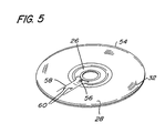
- Figure 5 is a perspective view of a second embodiment of an optical storage medium of the present invention.
- Figure 6 is a partially cut away perspective view of a third embodiment of an optical storage medium of the present invention.
- Figure 7 is a view of a cross-section of the optical storage medium shown in Figure 6.
- Figure 8 is an enlarged cross sectional view of the optical storage medium shown in Figure 6, taken along line 8-8.
- Figure 9 is an isometric view of a fourth embodiment of an optical storage medium of the present invention in an unopened vacuum sealed case.
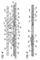
- Figure 10 is a partial sectional view, on an enlarged scale, of a portion of the edge of the case illustrated in Figure 9.
- Figure 11 is an exploded view of the optical storage medium stored in the unopened vacuum sealed case shown in Figure 9.
- Figure 12 is an enlarged cross sectional view of the optical storage medium stored in the unopened vacuum sealed case shown in Figure 9, taken along the line 12-12 in Figure 9.
- Figure 13 is an enlarged cross sectional view of a portion of the optical storage medium as shown in Figure 12, the case having been unsealed and subjected to atmospheric pressure prior to opening.
- optical storage medium 10 is a storage device in which data or other types of information may be stored and read, such as an audio and/or video compact disc (CD), a digital versatile disc (DVD), and the like.
- the optical storage medium 10 described herein is preferably a CD or DVD.
- Figure 1 shows the optical storage medium 10 in an environment presently known in the art, namely, removably stored within a case or storage container 12.
- the case 12 indudes a base 16 having a storage housing 18 that is shaped and dimensioned to receive the optical storage medium 10.
- a recess 20 in communication with the storage housing 18 provides a finger or thumb receiving portion of the base 16 so that the optical storage medium 10 may be grasped for easy removal.
- the base 16 is pivotably joined to a lid 14 by a living hinge.
- the lid 14 rotates about the hinge to enclose the optical storage medium 10 within the case 12.
- the case 12 shown in Figure 1 is merely exemplary of the type of CD or DVD cases presently known in the art and is not critical to the invention. Therefore, it is contemplated that the optical storage medium 10 of the present invention may be utilized and sold independent of the case 12.
- the optical storage medium 10 is shown in isolation, after having been removed from the case 12, for example.
- the optical storage medium 10 is circular, having an edge 22 that defines an outer periphery.
- the optical storage medium 10 includes a rigid substrate 26, as shown in Figures 2 and 3.
- the substrate 26 includes a central aperture or opening 24 and is made of transparent material, such as glass or plastic.
- the substrate 26 is made of transparent polycarbonate plastic having a first or top surface 25 and a second or bottom surface 27.
- the top and bottom surfaces 25 and 27 are spaced apart from each other by the thickness of the substrate 26, as best seen in Figure 3.
- the substrate 26 includes a data storage portion associated therewith on one surface, usually the bottom.
- the data storage portion includes readable data or information represented by pits or bumps formed within one or more radial tracks of the substrate 26 that are scanned by a laser to read the data.
- the data storage portion has a leading edge that is radially outward of the aperture 24, but inward of the edge 22.
- the data storage portion has been described as being formed within the substrate 26. However, other embodiments are contemplated. For example, it is contemplated that the data storage portion may be a separate layer of recordable and/or readable material that is supported by the substrate 26. In this way, the substrate 26 will provide support for the recording layer that provides the primary source of the readable data stored on the optical storage medium 10. Other suitable structures may be used.
- a relatively thin reflective layer 28 overlies the substrate 26.
- the reflective layer 28 provides a necessary reflective surface for the output of a laser so that the data stored on the optical storage medium 10 may be read.
- the reflective layer 28 is disposed on the top 25 surface of the substrate 26, having an inner edge 30 positioned radially outward of the aperture 24 and an outer edge 31 that is radially inward of edge 22.
- the reflective layer 28 is a thin sheet of reflective metallic material, such as aluminum.
- a reservoir or cavity 34 is associated with the substrate 26, as shown in Figure 2.
- the reservoir 34 is provided to releasably retain a preselected chemical agent that will render the optical storage medium 10 unreadable after a preselected period of time, as discussed in more detail below.
- the reservoir 34 is in communication with the reflective layer 28 or data storage portion of the substrate 26 and as shown in Figure 2, is located intermediate aperture 24 and edge 30.
- the reservoir 34 may be formed by a recess or well formed within the substrate 26.
- the reservoir 34 is a capsule that sits within the recess or on the top surface 25 of the substrate 26.
- the capsule has a relatively thin shell and releasably retains the preselected chemical agent. It should be understood that the location of the reservoir 34 shown in Figure 2 is merely exemplary, and may be located anywhere on or within the optical storage medium 10 to releasably retain the chemical agent.
- the chemical agent interacts with the optical storage medium 10 to render it unreadable after a preselected period of time by disrupting the ability of the laser to read the data stored in substrate 26.
- the chemical agent reacts with or dissolves the metallic material of reflective layer 28 so that the laser cannot read select portions of the data.
- aluminum has relatively low reactivity in that, due to its characteristics, it is instantly protected by a cover of oxide at any time. Despite this low reactivity, aluminum is known to react to certain chemicals under certain conditions and circumstances when the aluminum oxide is dissolved by a chemical agent that can, because of the dissolution of the oxide, react with the aluminum.
- aluminum is sensitive to bases such as NaOH or KOH, acids such as HCl, H 2 SO 4 , NHO 3 , and several metallic salts, such as CuSO 4 , as a few examples.
- the properties of these chemical agents may be advantageously used to facilitate and control the rate of dissolution or corrosion of the aluminum.
- the corrosion of an aluminum reflective layer 28 may be steady and uniform with certain agents, such as NaOH or HCl, or may become pitted upon exposure to agents such as CuSO 4 .
- a solution of NaOH with a concentration of 0.06 g/l and a pH of 11 generates a rate of dissolution of the aluminum reflective layer 28 ranging anywhere between approximately 0.3 micron per hour and approximately 1.0 micron per hour.
- Inhibitors like soda silicate can reduce or delay the action of NaOH, thereby reducing the rate of dissolution of the aluminum of the reflective layer 28, but extending the period over which the data will become unreadable.
- a solution of HCl with a concentration of 5.0% produces a rate of dissolution of the aluminum of the reflective layer 28 ranging anywhere between approximately 1.0 microns per 24 hours and approximately 3.0 microns per 24 hours.
- Inhibitors can reduce or delay the effects of the HCl even further, thereby reducing the rate of dissolution, but extending the period over which the data will be readable.
- a solution of CuSO 4 with a concentration of 1.0 % produces a rate of dissolution of the aluminum of the reflective layer 28 ranging anywhere between approximately 1.0 microns per 24 hours to approximately 2.0 microns per 24 hours.
- the dissolution of the aluminum, and the period after which the optical storage medium10 will become unreadable will depend on many factors. Those factors include the thickness of the aluminum and the characteristics of the chemical agent. For example, the relative thickness of the aluminum may be selectably adjusted to control the time needed by the chemical agent to at least partially dissolve the aluminum sufficiently to reach the polycarbonate layer or substrate 26 so as to destroy the availability of the data. The chemical properties of the chemical agent may also be selectably adjusted to control the period over which the data of a particular optical storage medium 10 will become unreadable. Another factor is the type of metallic material used for the reflective layer 28. Although aluminum is presently preferred, other types of metallic material having properties similar to aluminum may be used with the optical storage medium 10. Therefore, the type of metallic material used for the reflective layer 28 should be taken into account to determine the type, concentration, and amount of the chemical agent needed.
- a supply path 36 is provided on one side of the reflective layer 28 to control the distribution or flow of the chemical agent.
- the supply path 36 is in fluid communication with the reservoir 34 and is defined by borders or guides 38 that extends around the reservoir 34 and have an end that terminates radially inward of the edge 31 of the reflective layer 28.
- the borders 38 direct the flow of the chemical agent to the select portions of the reflective layer 28 when the chemical agent is released.
- each border 38 is a thin bead of material, such as glue, on the top surface of the reflective layer 28 so that they will not interfere with the reading of the data.
- a protective layer of material 32 is provided to prevent the spread of the chemical agent external to the optical storage medium 10 when released.
- the protective layer 32 is disposed over the reflective layer 28, and has an outer edge secured to the edge 22 of the substrate 26.
- the protective layer 32 may be made of plastic or other suitable material, such as an acrylic.
- the protective layer 32 is vacuum sealed to the substrate 26 to encapsulate the reservoir 34 and chemical agent in an airtight and liquid tight environment. In this way, the protective layer 32 enables the optical storage medium 10 to have the capacity to store in airtight conditions gases such as hydrogen that are generated by the chemical reaction between the chemical agent and the reflective layer 28. Once the protective layer 32 is sealed to the substrate 26, the chemical agent in the reservoir 34 will be stable until released.
- the protective layer 32 described above may be transparent or opaque. It is also contemplated that the exposed surface of the protective layer 32 may have applied thereon graphic or alphanumeric indica, advertising material, labels, and the like.
- the storage medium is held in place in case 12 by a retainer which also functions as a chemical reaction starting device 40 to selectably control the release of the chemical agent when the retainer is removed to permit removal of the storage medium.
- the starting device 40 is removably joined or secured to the optical storage medium 10 to prevent the optical storage medium 10 from being used until it is removed and the chemical agent released.
- the starting device includes a pair of rigid members or arms, a first 42 and a second 44, that extend radially outward from a central portion or bridge 45. Each rigid member 42 or 44 forms a handle so that the user may operate or remove the starting device 40, as discussed below.
- the starting device 40 is joined to the case by a screw 46.
- the screw 46 has an outer surface that is threaded and a hollow center.
- the center of the screw 46 includes an annular flange 49 that extends radially inwardly of the outer surface.
- the flange 49 has an inner edge that defines a hole that provides access to the hollow center of the screw 46.
- the flange 49 is provided to engage a locking collar 47 that extends downwardly from the bridge 45.
- the locking collar 47 includes a cylindrical body having an outer diameter that is slightly smaller than the hole formed by the flange 49.
- An annular flange or detent mechanism 51 extends radially outwardly from the distal end of the body of the collar 47, and is provided to snap-fit into the hollow portion of the screw 46.
- the bottom edge of the flange 51 is beveled to facilitate insertion of the locking collar 47 into the screw 46.
- the screw 46 terminates in a frangible portion 52 that is releasably joined to a hub 53.
- the hub 53 projects upwardly from the base 16 and is preferably cylindrical, having an outer surface with a diameter that is the same or slightly shorter than the central aperture 24 of the optical storage medium 10.
- the upper portion of the hub 53 is joined to the bottom portion of the screw 46 at a portion of reduced wall thickness to define the frangible portion 52.
- the frangible portion 52 is provided so that the starting device 40 and screw 46 may be removed from the optical storage medium 10.
- the bridge 45 supports a heel or projection member 50.
- the heel 50 projects downwardly from the rigid members 42 and 44 and includes a lower surface that sits over or lightly contacts the portion of the protective layer 32 that is positioned over the reservoir 34.
- the heel 50 extends radially and continuously around the screw 46 so that the lower portion will be in constant contact with the reservoir 34 no matter how the optical storage medium 10 is placed in the case 10.
- the heel 50 includes a drive 57 and a finger 59.
- the drive 57 extends around the inner portion of the heel 50 and engages the threads of the screw 46.
- the finger 59 extends downwardly at an angle relative to the rigid members 42 and 44, terminating at an end that lightly contacts the surface of the protective layer 32.
- the finger 59 conceals the screw 46 and prevents objects from getting underneath the heel 50.
- the optical storage medium 10 is seated within the housing 18 of the case 12, such that the screw 46 projects though the central aperture 24.
- the starting device 40 is joined.
- the starting device 40 is joined by inserting the locking collar 47 into the hole of the screw 46.
- the annular flange 51 of the locking collar 47 will engage the flange of 49 the screw 46 until its snaps in place such that the upper surface of the flange 51 of the locking collar 47 engages the lower surface of the flange 49 of the screw 46, as illustrated in Figure 4.
- the starting device 46 cannot be easily removed from the screw 46 by simply pulling it upwardly.
- the starting device 40 prevents the optical storage medium 10 from being used until the starting device 40 is removed. Once the starting device 40 is in place, a portion of the heel 50 will be positioned over the reservoir 34, as shown.
- the starting device 40 In operation, to use the optical storage medium 10, the starting device 40 must be removed. To remove the starting device 40, the rigid members 42 are rotated about the screw 46. As the rigid members 42 and 44 are rotated, the drive 57 will follow the grooves of the thread, moving generally downwardly toward the base 16. As the drive 57 moves downwardly, the heel 50 will exert a downwardly directed force or pressure on the reservoir 34 or capsule. The pressure exerted on the reservoir 34 facilitates or causes the release of the chemical agent, which then flows onto the preselected portion of the reflective layer 28 through the supply path 36, thereby starting the interaction between the chemical agent and optical storage medium 10. After a preselected period of time, the chemical agent will dissolve the reflective layer 28 to render the optical storage medium 10 unreadable, after which it has to be discarded. The dissolution of the reflective layer 28 can be observed by the consumer, indicating that the optical storage medium is unreadable.
- the rigid members 42 and 44 may be joined by screw 46 disposed within a hole or channel formed within the hub 53 of the case 12.
- screw 46 When the screw 46 is tightened to a preselected level of tension, the screw 46 will break apart so that the rigid members 42 and 44 may be removed from the case 12. Tightening screw 46 will also cause the head of the screw 46 to move downwardly toward the base 18, taking with it the drive 57 of the heel 50. As the drive 57 moves downwardly toward the base 18, the heel 50 will exert sufficient pressure on the reservoir 34 or capsule to release the chemical agent.
- the starting device 40 as shown in Figures 1 and 4.
- other devices may be used.
- the starting device 40 may be replaced by other types of mechanical devices or mechanisms, such as pressure release couplings, push-button devices, and other mechanical means.
- FIG. 5 shows an alternative embodiment of an optical storage medium 54.
- the optical storage medium 54 shown in Figure 5 is similar to the optical storage medium 10, described with reference to Figures 1-4 above.
- the optical storage medium 54 includes a substrate 26, a reflective layer 28, and a protective layer 32.
- a reservoir or capsule 56 is formed within the substrate 26, as described above, and is in communication with a supply path 58.
- the reservoir 56 is provided to releasably retain a preselected chemical agent in much the same way reservoir 34 releasably retains the chemical agent described with reference to the optical storage medium 10 of Figures 1-4.
- the chemical agent is provided to render the optical storage medium 54 unreadable after a preselected period of time.
- the reflective layer 28 includes small segments or pieces of a metal or metallic material 60 (two shown), such as copper, iron or any suitable alloy.
- the metal segments 60 are added to the surface of the reflective layer 28 that faces the protective layer 32.
- the segments 60 have an electrochemical potential different from the metallic material of the reflective layer 28.
- the chemical agent retained in the reservoir 56 to interact with the optical storage medium 54 is a solution having preselected electric conductivity with a pre-set level of concentration, such as NaCl. When the chemical agent is released, the chemical agent will flow onto select areas of the reflective layer 28 through supply path 58 toward the segments 60.
- the chemical agent facilitates an electrochemical reaction which dissolves selected portions of the reflective layer 28.
- the dissolution of the reflective layer 28 will form pits in the area of contact with the segments 60, which, in turn, disrupts the ability of the laser to read the data of the substrate 26 after a preselected period of time.
- the optical storage medium 54 or the data stored in the data storage portion 30 will become unreadable, after which it must be discarded.
- the dissolution of the reflective layer 28 should be observable to the user.
- the type and thickness of the metal segments 60 and the type of chemical agent may be selectably adjusted to control the period over which the select portions of the reflective layer 28 will be dissolved. It is also contemplated that one or a series of segments 60 may be used, in keeping with the scope of the present invention.
- Figures 6-8 show an alternative embodiment of an optical storage medium 62, which is in the form similar to a double sided DVD.
- the optical storage medium 62 includes a first substrate 64 and a second substrate 68. Both the first substrate 64 and second substrate 68 have a central hole or opening 66 and are made of transparent material, such as polycarbonate plastic, glass, ceramic, or the like.
- Each substrate 64 and 68 include a data storage portion for storing readable data (not shown) or include a separate layer of recording material to store the data.
- a reflective layer 72 is provided intermediate substrates 64 and 68.
- the reflective layer 72 provides a reflective surface so that data stored on each exposed side of substrates 64 and 68 may be read.
- the data is in the form of pits or bumps formed in radial tracks of the substrates 64 and 68 may be read by a laser.
- the laser passes through the corresponding substrate 64 or 68 and is reflected from the reflective layer 72.
- the reflective layer 72 is made of metallic material, such one or a pair of thin aluminum sheets that are bonded together, having an edge 76 that is radially inward of the hole 66, thereby creating a gap 73.
- a reservoir 78 is formed on one side of the optical storage medium 62.
- the reservoir 78 is provided to releasably retain a preselected chemical agent that is in communication with the data storage portion of the substrates 64 and 68.
- the chemical agent will render select portions of the data storage portion or reflective layer 72 unreadable after a preselected period of time when released.
- the chemical agent is in the form of a capsule similar to that described with reference to reservoir 34 of optical storage medium 10, described with reference to Figures 1-4.
- the reservoir 78 is in communication with a hole 80 that extends downwardly from the top of substrate 68.
- the hole 80 operates as a supply path and is in communication with the gap 73 that receives the chemical agent from the reservoir 78.
- the gap 73 is used as a means for directing the flow of the chemical agent onto the reflective layer 72 or data storage portion.
- a protective layer 79 will overlie the side of the optical storage medium 62 having the reservoir 78.
- the protective layer 79 is provided to encapsulate the reservoir 78 and its chemical agent in an airtight and liquid tight environment, in much the same way as the protective layer 32 described with reference to optical storage medium 10 creates an airtight and liquid tight environment, illustrated in Figures 1-4. As such, the release of the chemical agent will not flow outside of the optical storage medium 62.
- the release of the chemical agent of reservoir 78 is selectably caused or controlled by a chemical reaction starting device (not shown) that operates in much the same way as the chemical reaction starting device 40 illustrated in Figures 1 and 4, and described above in reference to optical storage medium 10.
- the starting device is removably secured to the optical storage medium 62. The starting device prevents the optical storage medium 62 from being used until it is removed and the chemical agent is released.
- the optical storage medium 62 is placed in a case, such as the type illustrated in Figures 1 and 4 described above.
- the starting device will prevent the optical storage medium 62 from being used until the starting device is removed.
- the rigid members of the starting device are rotated about the screw such that the heel will exert pressure on the reservoir 78.
- the pressure created on the reservoir 78 will cause the release of the chemical agent.
- the chemical agent from the reservoir 78 will flow through the hole and enter the gap 73.
- the chemical agent Upon entering the gap 73, the chemical agent will contact preselected areas of the reflective layer 72 which will start the interaction with the optical storage medium 62.
- the chemical agent will then dissolve the reflective layer 72 after a preselected period of time.
- the dissolution of the reflective layer 72 will disrupt the ability of the data of each substrate 64 and 68 to be read by a laser. As a result, the optical storage medium 62 will become unreadable.
- optical storage medium 62 has been described using a preselected chemical agent stored in reservoir 78.
- metal segments may be provided on select portions of the reflective layer 72, having an electrochemical potential different than the metallic material used for the reflective layer 72.
- an electrochemical reaction occurs between the two metals (i.e., the metal segment and the metallic material of the reflective layer 74) to form pits in the reflective layer 72, in much the same way as segments 60 dissolve reflective layer 28 of optical storage medium 54, described and illustrated in reference to Figure 5.
- optical storage media 10, 54 and 62 of the present invention have been described and illustrated relative to a case 12, for purposes of discussion only.
- the case 12 is not critical to the invention. Indeed, it is contemplated that the embodiments of the optical storage media of the present invention may be sold and utilized independent of or without the case 12.
- the starting device may include or be removably coupled to a support element that would support a screw or similar type of member removably joined to the hub. In this way, the starting device would still prevent the optical storage medium from being used until the chemical agent is released.
- the optical storage media (with the starting device releasably attached thereto) may be offered for sale and sold independent of the case 12.
- optical storage media This would help reduce costs associated with the sale of the optical storage media, which is particularly useful if the optical storage media are sold as one-time purchase items.
- Other embodiments of the starting device are contemplated which can be releasably secured to the optical storage media without a case.
- FIGS 9-13 show an alternative embodiment of the invention, in which the chemical agent is released not by mechanical action but by atmospheric pressure.
- FIG 9 illustrates a case or storage container 100 which holds an optical storage medium and a quantity of chemical agent in a reservoir.
- the case 100 has a lid 102 and a body 104, which is in the form of a shallow dish. Case 100 is illustrated as circular in shape, but may be square or rectangular, or any other shape, without departing from the scope of the invention.
- Both lid 102 and body 104 are made of an air-impermeable material, such as plastic.
- the lid 102 has an opening 106 in the center, shown in dashed lines in Figure 9, sealed by a frangible seal 108. Seal 108 is preferably a thin metallic foil, and is also air-impermeable.
- body 104 has a circumferential side wall 110 which extends upward from a bottom 112.
- Side wall 110 has a groove 114 around the inner surface thereof which receives a complementary tongue 116 in lid 102.
- the tongue 116 and groove 114 are sized and shaped to form an air-tight seal between lid 102 and body 104.
- case 100 contains a storage medium 118, such as for example a CD.
- CD 118 comprises a transparent substrate 120 and a thin reflective layer 122 on which are stored data to be read from the CD.
- the reflective layer 122 is a thin sheet of reflective metallic material, such as aluminum.
- a layer 124 of barrier material is applied to the reflective layer 122, and covers the entire reflective layer 122.
- the barrier layer 124 is usually printed with indicia to identify the CD and its contents, and also serves to protect the reflective layer from exposure to external elements.
- a CD to be rendered unreadable after a preselected time is provided with a barrier layer 124 over only about half of the reflective layer 122, leaving the remaining portion of reflective layer 122 exposed.
- a thin carrier layer 126 which carries a reservoir 128 of chemical agent, is placed over and adhered to the barrier layer 124 and reflective layer 122.
- the carrier layer is orientated so that the reservoir 128 lies over about the center of the barrier layer.
- body 104 of case 100 is provided with a recess 130 to receive reservoir 128 without subjecting reservoir 128 to mechanical pressure or deformation.
- At least one, and preferably two, beads 132 of adhesive are applied to the carrier layer 126 to attach it to CD 118.
- the beads 132 of adhesive also serve to define a channel 134 between them through which chemical agent released from reservoir 128 can flow onto reflective layer 122.
- the various parts are fabricated and assembled in a vacuum, such as inside a vacuum chamber. That is, the reservoir 128 is filled with chemical agent and the carrier layer 126 glued to CD 118 within the vacuum chamber. Then, CD 118, along with carrier layer 126 and reservoir 128, are placed into body 104 of case 100. Finally, lid 102 is snapped into place so that tongue 116 on lid 102 enters groove 114 on side wall 110 of body 104 to form an airtight seal. Since the CD 118 and attached carrier layer 126 are placed into case 100 in a vacuum environment, and since lid 102 is attached to body 104 in the same environment, the interior of case 100 will be under vacuum. The difference in pressure between the outside of case 100 (atmospheric pressure) and the inside of case 100 (vacuum) serves to hold lid firmly in place and prevent case 100 from being inadvertently opened.
- a vacuum such as inside a vacuum chamber. That is, the reservoir 128 is filled with chemical agent and the carrier layer 126 glued to CD 118 within
- Figure 12 is a cross-sectional view of an assembled case 100 containing a CD 118 and attached carrier layer 126 and reservoir 128, showing the interrelationship of the parts.
- the reservoir 128 is stable, and chemical agent can be retained in the reservoir indefinitely.
- the case 100 containing CD 118 can be shipped, stacked on shelves for storage, and otherwise handled without deleterious effect.
- case 100 must be opened to remove the CD.
- frangible seal 108 is broken, as indicated by the arrow in Figure 13.
- seal 108 is broken, air at atmospheric pressure is admitted to the interior of case 100. This subjects reservoir 128 to atmospheric pressure, rupturing it and forcing the chemical agent contained in reservoir 128 to flow out of the reservoir and onto the surface of CD 118.
- Channel 134 defined by beads 132 of adhesive, constrains the chemical agent to flow circumferentially and thus onto the portion of reflective layer 122 unprotected by barrier layer 124. Once the chemical agent reaches the unprotected portion of reflective layer 122, it begins to interact with the reflective layer, as in the previously described embodiments, eventually rendering the reflective layer unreadable.
- Breaking seal 108 and admitting air at atmospheric pressure into case 100 also makes it easy to remove lid 102 to permit removal of CD 118 from the case.
- optical storage media of the present invention provides several advantages in the content media market.
- the optical storage media of the present invention may be used as promotional material in point of sale purchases.
- the data stored in the optical storage media of the present invention may be used to offer on a trial basis software, music, movies, or other types of audio or visual data over a preselected period of time, such as a number of hours or days.
- the optical storage media will have to be discarded and the consumer will have to purchase the data on a more permanent storage medium.
- the optical storage media may be used by hotels to offer movies, either free or at a price, that must be used within a specific period of time, such as in a day or in a couple of hours, after which it must be discarded.
- the optical storage media of the present invention may be used in the movie rental industry. Often, movies in today's market are available to consumers as rental items in which the particular storage medium, such as a video cassette containing the movie, is rented for a fee. In exchange for paying the rental fee, the consumer is permitted to use the storage medium over a set period of time, such as three days, after which it has to be returned. At the end of three days, the video cassette is returned (if at all) and must be checked to ensure that it is rewound so that it may be rented again. However, by using the optical storage media of the present invention (such as an audio and/or visual DVD) as a rental item, the optical storage medium may be offered as a one-time purchase.
- the optical storage media of the present invention such as an audio and/or visual DVD
- the optical storage medium may be used for a preselected period of time, such as a couple of days, as desired. After the preselected period of time has expired, the optical storage media is discarded. In comparison to video cassettes, the content media distributor does not have to worry about the optical storage media being returned (if at all) and/or rewound. Rather, the content media distributor will simply have to maintain a supply of optical storage media to be purchased by the consumer. Thus, the costs associated with rental items such as movies may be reduced.
- the content media distributor can have more control over the extent to which copies of the data are made.
- the content media distributor may reduce the extent to which consumers will have the opportunity to make multiple copies of the data to avoid paying the cost to purchase the optical storage media.
- the risk of multiple copies there is the potential to increase in the amount of optical storage media that is purchased. As a result, the increased purchases have the potential to generate revenue to the content media distributor or the author or inventor of the work or data.
- optical storage medium such as the type shown in Figures 2, 5, and 6.
- the optical storage medium can have any shape or size, such that the cylindrical shape of the optical storage medium 10 shown in Figures 1-8 is only exemplary.
- the optical storage medium may be replaced by other types of audio, visual, or computer software data storage devices on which data or information may be selectably stored and read.
- the application of incorporating a preselected chemical agent to render the storage device unreadable over a preselected period of time may be incorporated into other types of data storage devices known in the art.
Landscapes
- Engineering & Computer Science (AREA)
- Signal Processing (AREA)
- Computer Security & Cryptography (AREA)
- Optical Record Carriers And Manufacture Thereof (AREA)
- Manufacturing Optical Record Carriers (AREA)
- Packaging For Recording Disks (AREA)
- Optical Recording Or Reproduction (AREA)
- Electrochromic Elements, Electrophoresis, Or Variable Reflection Or Absorption Elements (AREA)
- Addition Polymer Or Copolymer, Post-Treatments, Or Chemical Modifications (AREA)
- Crystals, And After-Treatments Of Crystals (AREA)
- Photovoltaic Devices (AREA)
Applications Claiming Priority (5)
| Application Number | Priority Date | Filing Date | Title |
|---|---|---|---|
| US43653899A | 1999-11-09 | 1999-11-09 | |
| US436538 | 1999-11-09 | ||
| US699903 | 2000-10-30 | ||
| US09/699,903 US6468619B1 (en) | 1999-11-09 | 2000-10-30 | Optical storage media having limited useful life |
| PCT/US2000/030678 WO2001035195A1 (en) | 1999-11-09 | 2000-11-08 | Optical storage media having limited useful life |
Publications (2)
| Publication Number | Publication Date |
|---|---|
| EP1228411A1 EP1228411A1 (en) | 2002-08-07 |
| EP1228411B1 true EP1228411B1 (en) | 2005-06-29 |
Family
ID=27031004
Family Applications (1)
| Application Number | Title | Priority Date | Filing Date |
|---|---|---|---|
| EP00977054A Expired - Lifetime EP1228411B1 (en) | 1999-11-09 | 2000-11-08 | Optical storage media having limited useful life |
Country Status (7)
| Country | Link |
|---|---|
| US (1) | US6468619B1 (enExample) |
| EP (1) | EP1228411B1 (enExample) |
| JP (1) | JP2003528414A (enExample) |
| AT (1) | ATE298901T1 (enExample) |
| AU (1) | AU1474501A (enExample) |
| DE (1) | DE60021101T2 (enExample) |
| WO (1) | WO2001035195A1 (enExample) |
Families Citing this family (30)
| Publication number | Priority date | Publication date | Assignee | Title |
|---|---|---|---|---|
| DE10261045A1 (de) * | 2002-12-24 | 2004-07-08 | Plaas-Link, Andreas, Dr.rer.nat. | Kopierschutz für Datenträger |
| US20040158871A1 (en) * | 2003-02-04 | 2004-08-12 | Bulldog Investments, Lp | Automated digital media vending apparatus |
| EP1611704A4 (en) * | 2003-03-18 | 2009-07-29 | Ensconce Data Technology | DEAD-ON-DEMAND DISK TECHNOLOGY |
| US20080219122A1 (en) * | 2003-03-18 | 2008-09-11 | Roger Detzler | Dead on demand technology |
| US7270866B2 (en) * | 2003-09-30 | 2007-09-18 | Dmitry A Noraev | Piracy-resistant data leasing system and method |
| US20050195728A1 (en) * | 2004-03-02 | 2005-09-08 | Fdd Technologies Sa/Ag/Ltd | Optical storage media having limited useful life |
| WO2006070344A2 (en) * | 2004-12-30 | 2006-07-06 | Dvtronix Ltd. | Optically readable disc |
| DE102005028520A1 (de) * | 2005-04-22 | 2006-11-02 | Markus Schedler | Datenträger, insbesondere optischer Datenträger, wie CD,DVD und dergleichen Speichermedium,. mit einer Entwertungsmöglichkeit |
| US20070020560A1 (en) * | 2005-05-27 | 2007-01-25 | Larson Lief C | Limited play optical discs |
| US20070122735A1 (en) * | 2005-11-30 | 2007-05-31 | Wisnudel Marc B | Optical storage device having limited-use content and method for making same |
| US7914870B2 (en) * | 2006-11-21 | 2011-03-29 | FDD Technologies sa/ag, Ltd. | Limited life medium |
| WO2008066702A2 (en) * | 2006-11-22 | 2008-06-05 | Fdd Technologies Sa/Ag/Ltd | Limited life medium |
| TWI352290B (en) * | 2007-05-09 | 2011-11-11 | Wei Shen | The optical storage media and the corresponding cr |
| US20090075015A1 (en) * | 2007-07-24 | 2009-03-19 | Detty Michael R | Limited Play Optical Discs |
| US8488428B2 (en) | 2008-05-14 | 2013-07-16 | Nbcuniversal Media, Llc | Enhanced security of optical article |
| US9795044B2 (en) | 2011-08-22 | 2017-10-17 | Catalyst Lifestyle Limited | Waterproof case |
| CN116170985A (zh) | 2011-08-22 | 2023-05-26 | 卡达利国际有限公司 | 防水盒 |
| US10045467B2 (en) * | 2014-06-24 | 2018-08-07 | David Lane Smith | System and method for fluid cooling of electronic devices installed in a sealed enclosure |
| US11191186B2 (en) | 2014-06-24 | 2021-11-30 | David Lane Smith | System and method for fluid cooling of electronic devices installed in an enclosure |
| US11744041B2 (en) | 2014-06-24 | 2023-08-29 | David Lane Smith | System and method for fluid cooling of electronic devices installed in an enclosure |
| USD924863S1 (en) | 2018-09-11 | 2021-07-13 | Catalyst Lifestyle Limited | Phone case |
| USD984425S1 (en) | 2018-09-11 | 2023-04-25 | Catalyst Lifestyle Limited | Mobile phone protection case |
| USD903685S1 (en) | 2019-03-29 | 2020-12-01 | Catalyst Lifestyle Limited | Electronic case |
| USD958146S1 (en) | 2019-06-20 | 2022-07-19 | Catalyst Lifestyle Limited | Case for electronic device |
| USD974330S1 (en) | 2019-06-26 | 2023-01-03 | Catalyst Lifestyle Limited | Case for electronic device |
| USD933075S1 (en) | 2019-06-26 | 2021-10-12 | Catalyst Lifestyle Limited | Case for a mobile communication device |
| US11076028B2 (en) | 2019-08-30 | 2021-07-27 | Catalyst Lifestyle Limited | Switch assembly for engaging a switch of an electronic device |
| USD931845S1 (en) | 2020-02-11 | 2021-09-28 | Catalyst Lifestyle Limited | Case for electronic communications device |
| USD932479S1 (en) | 2020-02-11 | 2021-10-05 | Catalyst Lifestyle Limited | Case for electronic communications device |
| USD984449S1 (en) | 2020-02-28 | 2023-04-25 | Catalyst Lifestyle Limited | Case for electronic device |
Family Cites Families (14)
| Publication number | Priority date | Publication date | Assignee | Title |
|---|---|---|---|---|
| US3688708A (en) | 1971-05-10 | 1972-09-05 | Gen Signal Corp | Transporter case |
| FR2475270A1 (fr) | 1980-02-01 | 1981-08-07 | Thomson Csf | Structure de memoire reversible, a inscription thermo-optique et lecture optique, et procede d'inscription et d'effacement de cette structure |
| US4635245A (en) | 1983-05-31 | 1987-01-06 | Ltv Aerospace And Defense Company | Frasable optical read/write data storage disc |
| US4637008A (en) | 1984-04-12 | 1987-01-13 | Ltv Aerospace And Defense | Optical erasable disk memory system utilizing duration modulated laser switching |
| JPS61129720A (ja) | 1984-11-27 | 1986-06-17 | Nagaoka:Kk | ヘツドクリ−ニング器 |
| EP0766239B1 (en) | 1985-07-08 | 2000-12-27 | Energy Conversion Devices, Inc. | A data storage device |
| US4737934A (en) | 1985-10-18 | 1988-04-12 | Energy Conversion Devices, Inc. | Data storage device and system having an optically non transmissive chalcogenide layer |
| US4818666A (en) | 1986-03-28 | 1989-04-04 | U.S. Philips Corporation | Erasable optical recording element and method of optically recording and erasing information |
| US4931770A (en) | 1987-10-02 | 1990-06-05 | Southern Integrity, Inc. | Protection system |
| US5056081A (en) | 1990-01-02 | 1991-10-08 | Tandy Corporation | System and method for erasing light-responsive optical disks |
| KR100364506B1 (ko) | 1994-03-25 | 2003-02-19 | 도레이 가부시끼가이샤 | 광기록매체및그제조법 |
| US5625524A (en) | 1994-07-28 | 1997-04-29 | Ricoh Company, Ltd. | Reversible thermosensitive recording medium and method of producing the same |
| US6011772A (en) | 1996-09-16 | 2000-01-04 | Spectradisc Corporation | Machine-readable optical disc with reading-inhibit agent |
| DE19857772A1 (de) | 1998-12-07 | 2000-06-08 | Reinhard Heerdegen | Zugriffsschutz für Software bestehend aus mit Hardware innerhalb eines Druckgefäßes verbundenen, gas- oder flüssigkeitsdruckempfindlichen Schaltern und die gesamte Anordnung ganz oder teilweise ummantelnden Kondensatorplatten |
-
2000
- 2000-10-30 US US09/699,903 patent/US6468619B1/en not_active Expired - Fee Related
- 2000-11-08 AU AU14745/01A patent/AU1474501A/en not_active Abandoned
- 2000-11-08 DE DE60021101T patent/DE60021101T2/de not_active Expired - Lifetime
- 2000-11-08 AT AT00977054T patent/ATE298901T1/de not_active IP Right Cessation
- 2000-11-08 WO PCT/US2000/030678 patent/WO2001035195A1/en not_active Ceased
- 2000-11-08 JP JP2001536663A patent/JP2003528414A/ja active Pending
- 2000-11-08 EP EP00977054A patent/EP1228411B1/en not_active Expired - Lifetime
Also Published As
| Publication number | Publication date |
|---|---|
| US6468619B1 (en) | 2002-10-22 |
| JP2003528414A (ja) | 2003-09-24 |
| AU1474501A (en) | 2001-06-06 |
| ATE298901T1 (de) | 2005-07-15 |
| WO2001035195B1 (en) | 2001-09-13 |
| WO2001035195A8 (en) | 2001-11-15 |
| DE60021101T2 (de) | 2006-05-24 |
| DE60021101D1 (de) | 2005-08-04 |
| EP1228411A1 (en) | 2002-08-07 |
| WO2001035195A1 (en) | 2001-05-17 |
Similar Documents
| Publication | Publication Date | Title |
|---|---|---|
| EP1228411B1 (en) | Optical storage media having limited useful life | |
| US20050195728A1 (en) | Optical storage media having limited useful life | |
| US6192025B1 (en) | Structure for protecting reading area of compact disc and device for applying same | |
| Byers | Care and Handling of CDs and DVDs—A Guide for Librarians and Archivists | |
| US6011772A (en) | Machine-readable optical disc with reading-inhibit agent | |
| JP4885397B2 (ja) | 読み取り可能なディスク | |
| GB2331981A (en) | Enclosure for holding a data carrier | |
| US4899330A (en) | Adaptor for mini CD | |
| JP2006518309A (ja) | 販売促進用コンパクトディスクキャリアシステム | |
| EP0989561B1 (en) | A device to install a compact disk media write protect device | |
| CN1211794A (zh) | 光盘用写保护环所用的连结系统 | |
| JPS5924479A (ja) | 磁気デイスクカ−トリツジ | |
| ES2287007T3 (es) | Inhibidor de lectura pseudoreflector para soportes de almacenamiento optico. | |
| JPH01211285A (ja) | 追記型光デイスク用廃棄処理材 | |
| JP2003524853A5 (enExample) | ||
| JP3728852B2 (ja) | 情報記録媒体収納ケース | |
| JP2003104479A (ja) | 記憶媒体の保護カバー | |
| JP2001266540A (ja) | 情報記録ディスク及び情報記録ディスク用ラベル | |
| US20080120634A1 (en) | Limited life medium | |
| KR200213661Y1 (ko) | 디지털 비디오 디스크 케이스 | |
| JP2005317094A (ja) | レンズクリーナーおよびその製造方法 | |
| JPH03203076A (ja) | 光記録ディスク用カートリッジおよび光記録ディスク | |
| KR20080033320A (ko) | 분실된 데이터에 대한 하이 레벨의 중복성 및 허용오차를갖는 카트리지 없는 소형 광 디스크 | |
| JPS63166036A (ja) | 情報記録媒体 | |
| JP2005108311A (ja) | 光磁気ディスク媒体 |
Legal Events
| Date | Code | Title | Description |
|---|---|---|---|
| PUAI | Public reference made under article 153(3) epc to a published international application that has entered the european phase |
Free format text: ORIGINAL CODE: 0009012 |
|
| 17P | Request for examination filed |
Effective date: 20020506 |
|
| AK | Designated contracting states |
Kind code of ref document: A1 Designated state(s): AT BE CH CY DE DK ES FI FR GB GR IE IT LI LU MC NL PT SE TR |
|
| AX | Request for extension of the european patent |
Free format text: AL;LT;LV;MK;RO;SI |
|
| 17Q | First examination report despatched |
Effective date: 20021029 |
|
| GRAP | Despatch of communication of intention to grant a patent |
Free format text: ORIGINAL CODE: EPIDOSNIGR1 |
|
| GRAS | Grant fee paid |
Free format text: ORIGINAL CODE: EPIDOSNIGR3 |
|
| GRAA | (expected) grant |
Free format text: ORIGINAL CODE: 0009210 |
|
| AK | Designated contracting states |
Kind code of ref document: B1 Designated state(s): AT BE CH CY DE DK ES FI FR GB GR IE IT LI LU MC NL PT SE TR |
|
| PG25 | Lapsed in a contracting state [announced via postgrant information from national office to epo] |
Ref country code: IT Free format text: LAPSE BECAUSE OF FAILURE TO SUBMIT A TRANSLATION OF THE DESCRIPTION OR TO PAY THE FEE WITHIN THE PRESCRIBED TIME-LIMIT;WARNING: LAPSES OF ITALIAN PATENTS WITH EFFECTIVE DATE BEFORE 2007 MAY HAVE OCCURRED AT ANY TIME BEFORE 2007. THE CORRECT EFFECTIVE DATE MAY BE DIFFERENT FROM THE ONE RECORDED. Effective date: 20050629 Ref country code: FI Free format text: LAPSE BECAUSE OF FAILURE TO SUBMIT A TRANSLATION OF THE DESCRIPTION OR TO PAY THE FEE WITHIN THE PRESCRIBED TIME-LIMIT Effective date: 20050629 Ref country code: NL Free format text: LAPSE BECAUSE OF FAILURE TO SUBMIT A TRANSLATION OF THE DESCRIPTION OR TO PAY THE FEE WITHIN THE PRESCRIBED TIME-LIMIT Effective date: 20050629 Ref country code: CH Free format text: LAPSE BECAUSE OF FAILURE TO SUBMIT A TRANSLATION OF THE DESCRIPTION OR TO PAY THE FEE WITHIN THE PRESCRIBED TIME-LIMIT Effective date: 20050629 Ref country code: BE Free format text: LAPSE BECAUSE OF FAILURE TO SUBMIT A TRANSLATION OF THE DESCRIPTION OR TO PAY THE FEE WITHIN THE PRESCRIBED TIME-LIMIT Effective date: 20050629 Ref country code: AT Free format text: LAPSE BECAUSE OF FAILURE TO SUBMIT A TRANSLATION OF THE DESCRIPTION OR TO PAY THE FEE WITHIN THE PRESCRIBED TIME-LIMIT Effective date: 20050629 Ref country code: LI Free format text: LAPSE BECAUSE OF FAILURE TO SUBMIT A TRANSLATION OF THE DESCRIPTION OR TO PAY THE FEE WITHIN THE PRESCRIBED TIME-LIMIT Effective date: 20050629 Ref country code: TR Free format text: LAPSE BECAUSE OF FAILURE TO SUBMIT A TRANSLATION OF THE DESCRIPTION OR TO PAY THE FEE WITHIN THE PRESCRIBED TIME-LIMIT Effective date: 20050629 |
|
| REG | Reference to a national code |
Ref country code: GB Ref legal event code: FG4D |
|
| REG | Reference to a national code |
Ref country code: CH Ref legal event code: EP |
|
| REF | Corresponds to: |
Ref document number: 60021101 Country of ref document: DE Date of ref document: 20050804 Kind code of ref document: P |
|
| REG | Reference to a national code |
Ref country code: IE Ref legal event code: FG4D |
|
| PG25 | Lapsed in a contracting state [announced via postgrant information from national office to epo] |
Ref country code: GR Free format text: LAPSE BECAUSE OF FAILURE TO SUBMIT A TRANSLATION OF THE DESCRIPTION OR TO PAY THE FEE WITHIN THE PRESCRIBED TIME-LIMIT Effective date: 20050929 Ref country code: SE Free format text: LAPSE BECAUSE OF FAILURE TO SUBMIT A TRANSLATION OF THE DESCRIPTION OR TO PAY THE FEE WITHIN THE PRESCRIBED TIME-LIMIT Effective date: 20050929 Ref country code: DK Free format text: LAPSE BECAUSE OF FAILURE TO SUBMIT A TRANSLATION OF THE DESCRIPTION OR TO PAY THE FEE WITHIN THE PRESCRIBED TIME-LIMIT Effective date: 20050929 |
|
| PG25 | Lapsed in a contracting state [announced via postgrant information from national office to epo] |
Ref country code: ES Free format text: LAPSE BECAUSE OF FAILURE TO SUBMIT A TRANSLATION OF THE DESCRIPTION OR TO PAY THE FEE WITHIN THE PRESCRIBED TIME-LIMIT Effective date: 20051010 |
|
| PG25 | Lapsed in a contracting state [announced via postgrant information from national office to epo] |
Ref country code: CY Free format text: LAPSE BECAUSE OF FAILURE TO SUBMIT A TRANSLATION OF THE DESCRIPTION OR TO PAY THE FEE WITHIN THE PRESCRIBED TIME-LIMIT Effective date: 20051108 Ref country code: IE Free format text: LAPSE BECAUSE OF NON-PAYMENT OF DUE FEES Effective date: 20051108 |
|
| PG25 | Lapsed in a contracting state [announced via postgrant information from national office to epo] |
Ref country code: LU Free format text: LAPSE BECAUSE OF NON-PAYMENT OF DUE FEES Effective date: 20051130 Ref country code: MC Free format text: LAPSE BECAUSE OF NON-PAYMENT OF DUE FEES Effective date: 20051130 |
|
| NLV1 | Nl: lapsed or annulled due to failure to fulfill the requirements of art. 29p and 29m of the patents act | ||
| PG25 | Lapsed in a contracting state [announced via postgrant information from national office to epo] |
Ref country code: PT Free format text: LAPSE BECAUSE OF FAILURE TO SUBMIT A TRANSLATION OF THE DESCRIPTION OR TO PAY THE FEE WITHIN THE PRESCRIBED TIME-LIMIT Effective date: 20051207 |
|
| REG | Reference to a national code |
Ref country code: CH Ref legal event code: PL |
|
| ET | Fr: translation filed | ||
| PLBE | No opposition filed within time limit |
Free format text: ORIGINAL CODE: 0009261 |
|
| STAA | Information on the status of an ep patent application or granted ep patent |
Free format text: STATUS: NO OPPOSITION FILED WITHIN TIME LIMIT |
|
| 26N | No opposition filed |
Effective date: 20060330 |
|
| REG | Reference to a national code |
Ref country code: IE Ref legal event code: MM4A |
|
| PGFP | Annual fee paid to national office [announced via postgrant information from national office to epo] |
Ref country code: GB Payment date: 20121227 Year of fee payment: 13 |
|
| PGFP | Annual fee paid to national office [announced via postgrant information from national office to epo] |
Ref country code: FR Payment date: 20130110 Year of fee payment: 13 |
|
| PGFP | Annual fee paid to national office [announced via postgrant information from national office to epo] |
Ref country code: DE Payment date: 20121231 Year of fee payment: 13 |
|
| GBPC | Gb: european patent ceased through non-payment of renewal fee |
Effective date: 20131108 |
|
| REG | Reference to a national code |
Ref country code: FR Ref legal event code: ST Effective date: 20140731 |
|
| PG25 | Lapsed in a contracting state [announced via postgrant information from national office to epo] |
Ref country code: DE Free format text: LAPSE BECAUSE OF NON-PAYMENT OF DUE FEES Effective date: 20140603 |
|
| REG | Reference to a national code |
Ref country code: DE Ref legal event code: R119 Ref document number: 60021101 Country of ref document: DE Effective date: 20140603 |
|
| PG25 | Lapsed in a contracting state [announced via postgrant information from national office to epo] |
Ref country code: GB Free format text: LAPSE BECAUSE OF NON-PAYMENT OF DUE FEES Effective date: 20131108 Ref country code: FR Free format text: LAPSE BECAUSE OF NON-PAYMENT OF DUE FEES Effective date: 20131202 |