EP1228328B1 - Vorrichtung zum umschalten eines mechanischen schaltmittels zwischen einem ersten schaltzustand und wenigstens einem zweiten schaltzustand - Google Patents
Vorrichtung zum umschalten eines mechanischen schaltmittels zwischen einem ersten schaltzustand und wenigstens einem zweiten schaltzustand Download PDFInfo
- Publication number
- EP1228328B1 EP1228328B1 EP01974002A EP01974002A EP1228328B1 EP 1228328 B1 EP1228328 B1 EP 1228328B1 EP 01974002 A EP01974002 A EP 01974002A EP 01974002 A EP01974002 A EP 01974002A EP 1228328 B1 EP1228328 B1 EP 1228328B1
- Authority
- EP
- European Patent Office
- Prior art keywords
- actuator
- state
- coupled
- shifting
- control element
- Prior art date
- Legal status (The legal status is an assumption and is not a legal conclusion. Google has not performed a legal analysis and makes no representation as to the accuracy of the status listed.)
- Expired - Lifetime
Links
Images


Classifications
-
- F—MECHANICAL ENGINEERING; LIGHTING; HEATING; WEAPONS; BLASTING
- F16—ENGINEERING ELEMENTS AND UNITS; GENERAL MEASURES FOR PRODUCING AND MAINTAINING EFFECTIVE FUNCTIONING OF MACHINES OR INSTALLATIONS; THERMAL INSULATION IN GENERAL
- F16H—GEARING
- F16H63/00—Control outputs from the control unit to change-speed- or reversing-gearings for conveying rotary motion or to other devices than the final output mechanism
- F16H63/02—Final output mechanisms therefor; Actuating means for the final output mechanisms
- F16H63/30—Constructional features of the final output mechanisms
- F16H63/34—Locking or disabling mechanisms
- F16H63/3416—Parking lock mechanisms or brakes in the transmission
- F16H63/3458—Parking lock mechanisms or brakes in the transmission with electric actuating means, e.g. shift by wire
-
- F—MECHANICAL ENGINEERING; LIGHTING; HEATING; WEAPONS; BLASTING
- F16—ENGINEERING ELEMENTS AND UNITS; GENERAL MEASURES FOR PRODUCING AND MAINTAINING EFFECTIVE FUNCTIONING OF MACHINES OR INSTALLATIONS; THERMAL INSULATION IN GENERAL
- F16H—GEARING
- F16H63/00—Control outputs from the control unit to change-speed- or reversing-gearings for conveying rotary motion or to other devices than the final output mechanism
- F16H63/02—Final output mechanisms therefor; Actuating means for the final output mechanisms
- F16H63/30—Constructional features of the final output mechanisms
- F16H63/304—Constructional features of the final output mechanisms the final output mechanisms comprising elements moved by electrical or magnetic force
-
- F—MECHANICAL ENGINEERING; LIGHTING; HEATING; WEAPONS; BLASTING
- F16—ENGINEERING ELEMENTS AND UNITS; GENERAL MEASURES FOR PRODUCING AND MAINTAINING EFFECTIVE FUNCTIONING OF MACHINES OR INSTALLATIONS; THERMAL INSULATION IN GENERAL
- F16H—GEARING
- F16H61/00—Control functions within control units of change-speed- or reversing-gearings for conveying rotary motion ; Control of exclusively fluid gearing, friction gearing, gearings with endless flexible members or other particular types of gearing
- F16H61/12—Detecting malfunction or potential malfunction, e.g. fail safe; Circumventing or fixing failures
- F16H2061/1256—Detecting malfunction or potential malfunction, e.g. fail safe; Circumventing or fixing failures characterised by the parts or units where malfunctioning was assumed or detected
- F16H2061/1292—Detecting malfunction or potential malfunction, e.g. fail safe; Circumventing or fixing failures characterised by the parts or units where malfunctioning was assumed or detected the failing part is the power supply, e.g. the electric power supply
-
- F—MECHANICAL ENGINEERING; LIGHTING; HEATING; WEAPONS; BLASTING
- F16—ENGINEERING ELEMENTS AND UNITS; GENERAL MEASURES FOR PRODUCING AND MAINTAINING EFFECTIVE FUNCTIONING OF MACHINES OR INSTALLATIONS; THERMAL INSULATION IN GENERAL
- F16H—GEARING
- F16H63/00—Control outputs from the control unit to change-speed- or reversing-gearings for conveying rotary motion or to other devices than the final output mechanism
- F16H63/02—Final output mechanisms therefor; Actuating means for the final output mechanisms
- F16H63/30—Constructional features of the final output mechanisms
- F16H63/304—Constructional features of the final output mechanisms the final output mechanisms comprising elements moved by electrical or magnetic force
- F16H2063/3066—Constructional features of the final output mechanisms the final output mechanisms comprising elements moved by electrical or magnetic force using worm gears
-
- F—MECHANICAL ENGINEERING; LIGHTING; HEATING; WEAPONS; BLASTING
- F16—ENGINEERING ELEMENTS AND UNITS; GENERAL MEASURES FOR PRODUCING AND MAINTAINING EFFECTIVE FUNCTIONING OF MACHINES OR INSTALLATIONS; THERMAL INSULATION IN GENERAL
- F16H—GEARING
- F16H61/00—Control functions within control units of change-speed- or reversing-gearings for conveying rotary motion ; Control of exclusively fluid gearing, friction gearing, gearings with endless flexible members or other particular types of gearing
- F16H61/12—Detecting malfunction or potential malfunction, e.g. fail safe; Circumventing or fixing failures
-
- F—MECHANICAL ENGINEERING; LIGHTING; HEATING; WEAPONS; BLASTING
- F16—ENGINEERING ELEMENTS AND UNITS; GENERAL MEASURES FOR PRODUCING AND MAINTAINING EFFECTIVE FUNCTIONING OF MACHINES OR INSTALLATIONS; THERMAL INSULATION IN GENERAL
- F16H—GEARING
- F16H63/00—Control outputs from the control unit to change-speed- or reversing-gearings for conveying rotary motion or to other devices than the final output mechanism
- F16H63/02—Final output mechanisms therefor; Actuating means for the final output mechanisms
- F16H63/30—Constructional features of the final output mechanisms
- F16H63/34—Locking or disabling mechanisms
- F16H63/3416—Parking lock mechanisms or brakes in the transmission
- F16H63/3458—Parking lock mechanisms or brakes in the transmission with electric actuating means, e.g. shift by wire
- F16H63/3466—Parking lock mechanisms or brakes in the transmission with electric actuating means, e.g. shift by wire using electric motors
-
- Y—GENERAL TAGGING OF NEW TECHNOLOGICAL DEVELOPMENTS; GENERAL TAGGING OF CROSS-SECTIONAL TECHNOLOGIES SPANNING OVER SEVERAL SECTIONS OF THE IPC; TECHNICAL SUBJECTS COVERED BY FORMER USPC CROSS-REFERENCE ART COLLECTIONS [XRACs] AND DIGESTS
- Y10—TECHNICAL SUBJECTS COVERED BY FORMER USPC
- Y10T—TECHNICAL SUBJECTS COVERED BY FORMER US CLASSIFICATION
- Y10T74/00—Machine element or mechanism
- Y10T74/19—Gearing
- Y10T74/19219—Interchangeably locked
- Y10T74/19251—Control mechanism
-
- Y—GENERAL TAGGING OF NEW TECHNOLOGICAL DEVELOPMENTS; GENERAL TAGGING OF CROSS-SECTIONAL TECHNOLOGIES SPANNING OVER SEVERAL SECTIONS OF THE IPC; TECHNICAL SUBJECTS COVERED BY FORMER USPC CROSS-REFERENCE ART COLLECTIONS [XRACs] AND DIGESTS
- Y10—TECHNICAL SUBJECTS COVERED BY FORMER USPC
- Y10T—TECHNICAL SUBJECTS COVERED BY FORMER US CLASSIFICATION
- Y10T74/00—Machine element or mechanism
- Y10T74/20—Control lever and linkage systems
- Y10T74/20012—Multiple controlled elements
- Y10T74/20018—Transmission control
- Y10T74/2003—Electrical actuator
Definitions
- the invention relates to a device for switching a mechanical switching means between a first switching state and at least a second switching state, in particular for switching on and off of a parking brake for an automatic transmission.
- a conventional automatic transmission for motor vehicles is usually associated with at least four modes corresponding to the following shift positions of a shift lever, namely, "P", “R”, “N” and “D".
- P indicates the state "parking”, usually in this state, the transmission is locked by the parking brake mechanically against a transfer of movements.
- R indicates the "reverse operation”
- D the "forward operation and the shift position” N "corresponds to the" neutral operation "in which there is no mechanical coupling between the engine and the wheels.
- a common safety requirement is that the mechanical parking lock of the automatic transmission can always be inserted or is engaged when the vehicle is at a standstill.
- a mechanical transmission member such as a shift cable or a shift linkage
- this safety requirement is relatively easy to meet because of the mechanical transmission member coupling between the actual switching state of the transmission and the indicated switching state of the shift lever is forced, at least as long as the mechanical transmission member is not defective.
- the shift lever can be brought into the "P" position and the automatic transmission can be switched to the corresponding state with the parking brake engaged via the mechanical coupling.
- the generic JP 07 277156 A discloses a device for switching a mechanical switching means between a first and a second switching state.
- an actuator is coupled in the formation of a brake lever.
- a lever is pivotally articulated. This lever is coupled via an electromagnetic clutch with a drive device.
- a tension spring is arranged between the lever and an abutment, which transfers the actuator with a separate clutch into a position of the switching means defining the first switching state via the lever.
- the invention has for its object to provide a device with which the above-mentioned safety requirement for an automatic transmission can be fulfilled even when using an electromechanical transmission element.
- a device having the features of claim 1 is provided according to the invention. Preferred developments are claimed in the subclaims.
- the inventive device for switching a mechanical switching means between a first switching state and at least a second Switching state has an actuator coupled to the switching means for switching between the switching states, wherein the actuator can be coupled via a coupling device with a control member.
- Each switching state of the switching means is assigned a specific position of the actuator, so that the switching means can be switched to an arbitrary switching state of the first and at least the second switching state by the actuator is brought into the arbitrary switching state associated position.
- a change in position of the actuator can be brought about for example by a displacement, a twisting or a pivoting.
- the actuator In the coupled state, the actuator may be driven by the control member, the control member itself being actuated by a drive device.
- the actuator By driving the control member thus the actuator can be brought into the different, the switching states associated positions. For each of these positions of the actuator is in turn assigned a specific position of the control member, in which this can be brought by means of the drive means.
- the coupling device can be actuated via an electrical signal, which means that the actuator is coupled to the control member of the latter, when the electrical signal assumes a certain state. It may be an almost arbitrary state, as long as it is ensured that this differs from the signal state in the event of a failure of the electrical signal, whereby failure of the electrical signal is to be understood as a power failure, for example. In the case of failure of the electrical signal then the coupling between the actuator and the control member is released from the coupling device, so that these two members are again decoupled from each other.
- a spring means is coupled to the actuator and an abutment which is biased in each of the first switching state different switching state with respect to the actuator such that in the case of decoupling between the actuator and the control member, the actuator is switched by the spring means while reducing the voltage thereof in the first switching state associated position, whereby the switching means is switched to the first switching state. Since the spring means is coupled to the actuator and the abutment, the required for the return of the actuator in the first switching state associated position voltage of the spring means can be constructed by a relative change in position between or by a relative movement of the actuator and the abutment.
- the device according to the invention can be used wherever a particular of at least two switching states of a mechanical switching means should be safely switched on in the event of a power failure.
- the device according to the invention is preferably used for switching on or off a parking lock of an automatic transmission.
- the switching means is designed as a parking brake of the automatic transmission, wherein the first switching state corresponds to the state of the engaged parking brake and the at least second switching state the state of the disabled parking brake.
- the actuator is coupled via a shaft to the switching means, wherein the switching means is switched over a rotational movement of the shaft between the first and the at least second switching state.
- the actuator is rotatably connected to the shaft.
- the control member can transmit a translational movement in the coupled state, which on the actuator in a rotational movement for switching between can be converted to different states.
- the control member is rotatably mounted with respect to the shaft, wherein the actuator and the control member are rotatably connected to each other in the coupled state.
- the coupled state of the actuator and the control member can be realized by means of a general form or adhesion.
- the coupled state can be realized on the principle of a friction clutch, wherein the actuator, the control member and the coupling device are designed according to the structure of such a friction clutch.
- the actuator and the control member are formed such that a tooth holding brake (toothed coupling) is formed by these two members.
- both the actuator and the control member are formed as discs, whose opposing surfaces are each provided with a plurality of teeth.
- the actuator and the control member are held together by a coupling force exerted by the coupling device, wherein the teeth of the control member engage in the spaces between the teeth of the actuator and vice versa.
- the teeth of the actuator are in operative connection with the teeth of the control member, whereby a rotationally fixed connection between the control member and the actuator is formed, as long as the coupling force is maintained by the coupling device.
- the geometric configuration of the teeth is such that upon transmission of a torque from the actuator to the control member, or vice versa, a release force acts on the two members, which forces the control member and the actuator apart. Therefore, if the coupled state between the actuator and the control member is to be maintained, the amount of the coupling force must always be greater than or at least equal to the amount of the release force be. In a loss of coupling force and a simultaneous transmission of torque from the actuator to the control member or vice versa, the control member and the actuator are relatively moved apart until the teeth no longer engage in the interstices.
- the gear coupling has the advantage that the rotationally fixed connection between the actuator and the control member is automatically released when the two members are no longer held together by the coupling force.
- the toothed coupling is designed such that due to the release force, the control member is moved away from the actuator.
- the spring means may be formed by any mechanical spring, which is adapted to reset the switching means located in the at least second switching state in the decoupled state in the first switching state.
- the spring means is a coil spring, leg spring or helically wound bending spring attached to the actuator and to the abutment, wherein the return of the switching means in the first switching state via the rotationally fixed connection between the actuator and the shaft.
- the spring means in the second switching state must have a certain restoring tension. For this purpose, it may be necessary to provide a certain minimum preload already in the first switching state at the spring means.
- the spring means is coupled to the actuator and to the abutment, wherein, according to a first alternative, the abutment is provided on the automatic transmission or on a fixed relative to the automatic transmission. If the actuator for switching on the second switching state, for example, brought by a rotational movement in the second switching state associated position, so at the same time the spring means is tensioned to the reset voltage.
- the arrangement of the abutment according to the first alternative has the consequence that when switching from the first to the second switching state each time the work for tensioning the spring means must be applied. Further, the work to be done for switching becomes larger as the actuator continues to move. This effect may be undesirable in some applications for the device according to the invention.
- the abutment is provided on the control member.
- the control member is biased against the actuator to the reset voltage in the decoupled state. Only then the actuator and the control member are coupled together via the coupling device. In the coupled state, therefore, when switching over from the first switching state to the at least second switching state, no more work has to be done to tension the spring means, since there is no relative movement between the actuator and the control member or the abutment.
- the voltage of the spring means is set constant in the coupled state to the reset voltage, so that the voltage of the spring means according to the second alternative in each switching state is constant.
- the actuator in the uncoupled state, can be reset in the first switching state associated position of the spring means, the control member must be set during the return operation relative to the actuator, so that relax the spring means only on the return of the actuator or reduce its voltage can.
- This determination of the control member can for example be effected in that the control member is driven by the drive means via a transmission with self-locking, such as a worm gear.
- the coupling device has the task of coupling the control member and the actuator together.
- the coupling member may move the control member to form a mechanical contact with the actuator, or vice versa, with the control of the Coupling device, a coupling force is exerted over which the actuator and the control member are juxtaposed and held together.
- the coupling between the actuator and the control member under certain conditions. This can be realized, for example, in that the coupling device in the uncoupled state no longer exerts coupling force on the control member or on the actuator.
- the coupling device may be designed such that from this to take the uncoupled state, the control member is moved away from the actuator or vice versa.
- the coupling device can be designed, for example, pneumatically, hydraulically or electrostatically.
- the coupling device is designed to be magnetic, wherein the coupling device has a magnetizable region both on the actuator and on the control member and at least one of the magnetizable regions is formed by an electromagnet which can be activated by the electrical signal.
- this preferred magnetic coupling device is provided on the actuator of the electromagnet and the control member of the magnetizable region of ferromagnetic material.
- the electromagnet When the electromagnet is passed through by an electrical current forming the electrical signal, the magnetic field generated by the electromagnet interacts with the ferromagnetic region on the control member in such a way that the control member is attracted by the electromagnet.
- the force of attraction caused by the activated electromagnet in cooperation with the ferromagnetic contact area causes, as a coupling force, the control member and the actuator to be juxtaposed and held together. If the electrical current fails for any reason, then the magnetic field of the electromagnet breaks down, and there is no coupling force exerted to hold the actuator and the control member together.
- the electromagnet on the control member and the ferromagnetic region on the actuator.
- the ferromagnetic region can also be replaced by a second magnet, in particular a second electromagnet.
- the device according to the invention is integrated into a larger, multi-component system with a system control, a failure of individual components of the system is possible without the electrical signal fails. Nevertheless, it may be important for safety reasons that the switching means is switched to the first switching state in such situations. For this reason, in the event of a failure of the electrical signal, the signal state can also be brought about under the control of the system control, by bringing the electrical signal from it into the state which it assumes when it fails.
- FIGS. 1 to 3 show a first embodiment of the device according to the invention for switching over a mechanical switching means, which is denoted overall by the reference numeral 1.
- the device 1 for switching a mechanical switching means is provided on an automatic transmission 2 and serves at least for switching between the four modes "P", “R”, “N” and “D”. Between the different operating modes of the automatic transmission can be switched over the rotation of a shaft 3, wherein one of the operating mode "P” associated angular position of the shaft 3, this can be rotated in a positive direction defined rotation to the other modes “R", Turn on “N” and “D". In this case, the operating modes "R", “N” and “D” correspond in this order to an increasing rotation of the shaft 3 in the positive direction of rotation.
- An actuator 4 designed as a first toothed disk of a toothed clutch is arranged concentrically with and against rotation on the shaft 3.
- a designed as a second toothed wheel of the toothed clutch control member 5 is also concentric with but mounted with a clearance on the shaft 3, wherein on the facing surfaces of the two toothed disks each one concentric to the shaft gear rim 6, 7 is provided.
- the teeth of the toothed ring 6 arranged on the actuator 4 are from the actuator 4 in the direction of the control member 5 from. Further, the teeth of the arranged on the control member 5 sprocket 7 from the control member 5 in the direction of the actuator 4 from.
- the sprockets 6 and 7 have the same diameter and are formed such that the teeth of the arranged on the actuator 4 ring gear 6 can engage in the spaces between the teeth of the arranged on the control member 5 sprocket 7 and vice versa, when the control member 5 with the Actuator 4 is brought into contact.
- the geometrical configuration of the individual teeth of the two sprockets 6, 7 is such that a release force is caused by the transmission of torque from the control member 5 to the actuator 4 or vice versa, which acts on the control member 5 and pushes it away from the actuator 4. If the release force is not opposed by a coupling force which the control member 5 presses on the actuator 4, the control member 5 is moved away from the actuator 4 to a position at a sufficiently high release force, in which the teeth of the two sprockets 6, 7 no longer intermesh , Without coupling force so no rotationally fixed connection between the actuator 4 and the control member 5 is present, whereby the uncoupled state is identified. This is true even if the coupling force is present, but the amount is smaller than the dissolving force.
- the actuator 4 and the control member 5 are in contact with each other.
- the two sprockets 6, 7 engage with each other and form a rotationally fixed connection between the actuator 4 and the control member 5, whereby the coupled state is characterized.
- the control member 5 has at its periphery a row of teeth 8 with radially aligned teeth, which forms part of a circular arc.
- a gear 9 in which engages a driven by a motor 10 cylindrical screw 11.
- the cylindrical screw 11 and the Gear 9 form a worm gear with self-locking, via which the control member 5 can be driven by the motor 10 and rotated.
- the motor 10, the cylindrical worm 11 and the gear 9 form, in cooperation with the row of teeth 8, the driving device for driving the control member 5.
- an electromagnet 12 is provided, and the control member 5 is made of ferromagnetic material.
- the two toothed rings 6, 7 engage with one another, whereby the rotationally fixed connection between the actuator 4 and the control member 5 is formed.
- the actuator 4 and the control member 5 are thus in the coupled state, in which the coupling force caused by the current-carrying magnet in cooperation with the ferromagnetic material is always greater than the release force of the toothed coupling.
- the shaft 3 can be rotated by the motor 10, so that it can be switched by means of the motor 10 between the different modes of the automatic transmission 2.
- the engine 10 is driven by an electronic circuit, not shown, such that the switched-in automatic transmission 2 mode corresponds to the switching position of the shift lever in the passenger cabin of the motor vehicle.
- the shaft 3 can be rotated by the motor 10 either in the positive or in the negative direction of rotation.
- a leg spring 13 is fixed with one end, the other end is attached to a provided on the automatic transmission 2 abutment 14.
- the leg spring 13 is fixed between the actuator 4 and the abutment 14 so that it has its lowest voltage in the mode "P”, which is hereinafter referred to as bias.
- the shaft 3 is rotated via the actuator 4 in the positive direction of rotation, wherein the leg spring 13 is additionally tensioned beyond the bias.
- the work for additional tensioning of the leg spring is applied by the motor 10 in the coupled state.
- the actuator 4 can be turned back from the leg spring 13, a certain minimum voltage of the leg spring 13 is required, which is referred to as reset voltage.
- the leg spring 13 has in each of "P" different mode at least this reset voltage in order to ensure safe switching on the parking brake of the automatic transmission 2 in case of power failure. For this reason, it may be necessary, the leg spring 13 already in the operating mode "P" associated angular position of the Actuator 4 to apply a certain minimum bias.
- the minimum bias voltage is not reduced when the toothed clutch is in the decoupled state, for example, a stop on the automatic transmission 2 and a pin on the actuator 4 is provided, which abuts in the operating mode "P" associated angular position of the actuator 4 to the stop.
- the pin and the stop act in such a way that the actuator 4 can not be rotated in the "P" associated with the angular position in the negative direction of rotation. This is a reduction of the minimum bias safely prevented.
- FIGs. 4 to 6 there is shown a second embodiment of the mechanical switching means switching device according to the present invention, wherein the reference numerals used for the features of the second embodiment are the same as those of the first embodiment used for the same or similar features.
- the second embodiment is identical except for the arrangement of the leg spring 13 and the abutment 14 structurally with the first embodiment.
- the stopper on the automatic transmission 2 and the pin on the actuator 4 can be omitted.
- the leg spring 13 is arranged between the actuator 4 and the control member 5.
- the abutment 14 is provided on the control member 5, so that the leg spring 13 is attached at its one end to the actuator 4 and at its other end to the provided on the control member 5 abutment 14.
- the leg spring 13 is secured between the actuator 4 and the abutment 14 so that it has its lowest voltage in the uncoupled state.
- the coupled state must be made between the actuator 4 and the control member 5, which is preferably done in the switching position "P" of the automatic transmission 2.
- the steering wheel 5 is rotated by the motor 10 in the positive direction of rotation until the tension of the leg spring 13 corresponds to the restoring tension, the restoring tension in this case being understood to mean the tension required to drive the automatic transmission 2 out of any of " P "different mode out in the operating mode” P "back. Only when the voltage of the leg spring 13 has reached the reset voltage, the actuator 4 and the control member 5 are coupled together via the electromagnet 12.
- the actuator 4 may be secured during the clamping operation via a mechanism against rotation, from which the actuator 4 is released again after the clamping operation.
- the shaft 3 is then rotated by the motor 10 via the coupled gear coupling in the positive direction of rotation, the voltage of the leg spring 13 for all modes of Automatic transmission 2 is set constant to the reset voltage as long as the coupled state is maintained.
- the power supply for the electromagnet 12 also breaks down, and no additional coupling force acts on the control member 5.
- the torque transmitted to the actuator 4 by the leg spring 13 stretched to the reset voltage causes the control member 5 to be moved away from the actuator due to the release force.
- the actuator 4 of the leg spring 13 due to your Turned back tension in the angular position assigned to the mode "P", whereby at the same time the automatic transmission 2 via the shaft 3 in the mode "P" is switched back, in which the parking brake is turned on.
- the actuator 4 can also be rotated back by the leg spring 13, a determination of the control member 5 in terms of rotational movement relative to the actuator 4 is required in the uncoupled state. This is not required in the first embodiment determination is made by the worm gear formed by the cylindrical screw 11 and the gear 9, which has a sufficiently high self-locking to prevent twisting of the control member 5 due to the spring tension of the leg spring 13.
Landscapes
- Engineering & Computer Science (AREA)
- General Engineering & Computer Science (AREA)
- Mechanical Engineering (AREA)
- Gear-Shifting Mechanisms (AREA)
- Control Of Transmission Device (AREA)
Description
- Die Erfindung betrifft eine Vorrichtung zum Umschalten eines mechanischen Schaltmittels zwischen einem ersten Schaltzustand und wenigstens einem zweiten Schaltzustand, insbesondere zum Ein- und Ausschalten einer Parksperre für ein Automatikgetriebe.
- Aus dem Stand der Technik sind Automatikgetriebe mit einer mechanischen Parksperre bekannt. Einem herkömmlichen Automatikgetriebe für Kraftfahrzeuge sind in der Regel wenigstens vier Betriebsarten zugeordnet, die zu folgenden Schaltstellungen eines Schalthebels korrespondieren, nämlich "P", "R", "N" und "D". Bei den einzelnen Schaltstellungen kennzeichnet "P" den Zustand "Parken", wobei üblicherweise in diesem Zustand das Getriebe durch die Parksperre mechanisch gegen ein Übertragen von Bewegungen gesperrt ist. "R" kennzeichnet den "Rückwärtsfahrbetrieb", "D" den "Vorwärtsfahrbetrieb und die Schaltstellung "N" entspricht dem "Neutralbetrieb", in dem keine mechanische Koppelung zwischen dem Motor und den Rädern vorhanden ist.
- Eine übliche Sicherheitsanforderung ist, dass die mechanische Parksperre des Automatikgetriebes im Stillstand des Fahrzeuges stets eingelegt werden kann bzw. eingelegt ist.
Mit einer Automatikschaltung, bei der ein mechanisches Übertragungsglied, wie zum Beispiel ein Schaltzug oder ein Schaltgestänge, zwischen dem Schalthebel und dem Automatikgetriebe vorgesehen ist, ist diese Sicherheitsanforderung relativ einfach zu erfüllen, da wegen des mechanischen Übertragungsgliedes eine Koppelung zwischen dem tatsächlichen Schaltzustand des Getriebes und dem angezeigten Schaltzustand des Schalthebels erzwungen wird, jedenfalls solange das mechanische Übertragungsglied nicht defekt ist. Selbst bei einem Stromausfall im Fahrzeug kann der Schalthebel in die Schaltstellung "P" gebracht und über die mechanische Koppelung das Automatikgetriebe in den entsprechenden Zustand mit eingeschalteter Parksperre geschaltet werden. - In jüngster Zeit sind allerdings elektromechanische Übertragungsglieder für die Automatikschaltung entwickelt worden, wobei eine mechanische Koppelung zwischen dem Automatikgetriebe und dem Schalthebel nicht mehr vorgesehen ist. In diesem Fall werden die Schaltzustände des Schalthebels elektronisch erfasst und in Form von diesen zugeordneten elektrischen Signalen einer Vorrichtung (Getriebeaktuatorik) zugeführt, welche an Stelle des mechanischen Übertragungsgliedes das Automatikgetriebe in die der Schaltstellung des Schalthebels entsprechende Betriebsart stellt. Ein solcher elektromechanischer Schaltvorgang wird auch mit dem englischen Ausdruck "shift-by-wire" bezeichnet.
- Bei der elektromechanischen Koppelung zwischen dem Schalthebel und dem Automatikgetriebe ist es allerdings möglich, dass bei einem Stromausfall im Fahrzeug für das Getriebe eine andere Betriebsart eingestellt ist, als vom Schalthebel angezeigt wird, da der Schalthebel mechanisch unabhängig von der Getriebeaktuatorik betätigt werden kann. Somit ist aber die oben angesprochene Sicherheitsanforderung nicht mehr in jedem Fall erfüllbar.
- Die gattungsbildende JP 07 277156 A offenbart eine Vorrichtung zum Umschalten eines mechanischen Schaltmittels zwischen einem ersten und einem zweiten Schaltzustand. Mit dem als Trommelbremse ausgebildeten Schaltmittel, wobei der anliegende Bremsbelag einen ersten Schaltzustand und der gelöste Bremsbelag einen zweiten Schaltzustand definiert, ist ein Stellglied in der Ausbildung eines Bremshebels gekoppelt. An dem Stellglied ist einenends ein Hebel schwenkbar angelenkt. Dieser Hebel ist über eine elektromagnetische Kupplung mit einer Antriebseinrichtung gekoppelt. Anderenends ist zwischen dem Hebel und einem Widerlager eine Zugfeder angeordnet, welche über dem Hebel das Stellglied bei getrennter Kupplung in eine den ersten Schaltzustand definierende Stellung des Schaltmittels überführt. Bei eingerasteter Kupplung hingegen wird das Schaltmittel mittels der Antriebseinrichtung und den daran über eine oszillierende Scheibe gekoppelten Hebel sowie das Stellglied in den zweiten Schaltzustand versetzt.
- Da zwischen dem Stellglied und dem Hebel stets eine mechanische, nicht entkuppelbare Verbindung besteht und sich der Hebel in einer Totpunktstellung befinden kann, ist nicht sichergestellt, dass die Zugfeder das Schaltmittel stets in den ersten Schaltzustand überführt, bei dem eine Bewegung des an das Schaltmittel angebunden Getriebes verhindert wird. Zudem baut die Vorrichtung sehr groß auf und besteht aus vielen Bauteilen, womit die Vorrichtung auch kostenintensiv wird.
- Der Erfindung liegt die Aufgabe zugrunde, eine Vorrichtung zu schaffen, mit der die oben angesprochene Sicherheitsanforderung für ein Automatikgetriebe auch bei Verwendung eines elektromechanischen Übertragungsgliedes erfüllbar ist. Zur Lösung dieser Aufgabe wird erfindungsgemäß eine Vorrichtung mit den Merkmalen nach dem Patentanspruch 1 geschaffen. Bevorzugte Weiterbildungen sind in den Unteransprüchen beansprucht.
- Die erfindungsgemäße Vorrichtung zum Umschalten eines mechanischen Schaltmittels zwischen einem ersten Schaltzustand und wenigstens einem zweiten Schaltzustand weist ein mit dem Schaltmittel gekoppeltes Stellglied zum Umschalten zwischen den Schaltzuständen auf, wobei das Stellglied über eine Kuppelvorrichtung mit einem Steuerglied gekuppelt werden kann.
- Jedem Schaltzustand des Schaltmittels ist eine bestimmte Position des Stellgliedes zugeordnet, so dass das Schaltmittel in einen beliebigen Schaltzustand von dem ersten und dem wenigstens zweiten Schaltzustand geschaltet werden kann, indem das Stellglied in die dem beliebigen Schaltzustand zugeordnete Position gebracht wird. Eine Positionsänderung des Stellgliedes kann zum Beispiel durch ein Verschieben, ein Verdrehen oder ein Verschwenken herbeigeführt werden.
- Im gekuppelten Zustand kann das Stellglied von dem Steuerglied angetrieben bzw. betätigt werden, wobei das Steuerglied selbst von einer Antriebsvorrichtung betätigt bzw. angetrieben wird. Durch das Antreiben des Steuergliedes kann somit das Stellglied in die unterschiedlichen, den Schaltzuständen zugeordneten Positionen gebracht werden. Dafür ist jeder dieser Positionen des Stellgliedes wiederum eine bestimmte Position des Steuergliedes zugeordnet, in welche dieses mittels der Antriebseinrichtung gebracht werden kann.
- Die Kuppelvorrichtung kann über ein elektrisches Signal betätigt werden, was heißt, dass das Stellglied mit dem Steuerglied von dieser gekuppelt wird, wenn das elektrische Signal einen bestimmten Zustand annimmt. Es kann sich dabei um einen nahezu beliebigen Zustand handeln, sofern sichergestellt ist, dass sich dieser von dem Signalzustand bei einem Ausfall des elektrischen Signals unterscheidet, wobei unter Ausfall des elektrischen Signals zum Beispiel ein Stromausfall zu verstehen ist. Im Falle des Ausfalls des elektrischen Signals wird dann die Kuppelung zwischen dem Stellglied und dem Steuerglied von der Kuppelvorrichtung freigegeben, so dass diese beiden Glieder wieder voneinander entkuppelt sind.
- Für eine sichere Rückstellung des Schaltmittels in den ersten Schaltzustand bei Ausfall des elektrischen Signals ist mit dem Stellglied und einem Widerlager ein Federmittel gekoppelt, welches in jedem von dem ersten Schaltzustand verschiedenen Schaltzustand hinsichtlich des Stellgliedes derart gespannt ist, dass im Falle einer Entkuppelung zwischen dem Stellglied und dem Steuerglied, das Stellglied von dem Federmittel unter Verringerung der Spannung desselben in die dem ersten Schaltzustand zugeordnete Position geschaltet wird, wodurch auch das Schaltmittel in den ersten Schaltzustand geschaltet wird. Da das Federmittel mit dem Stellglied und dem Widerlager gekoppelt ist, kann die für die Rückstellung des Stellgliedes in die dem ersten Schaltzustand zugeordnete Position erforderliche Spannung des Federmittels durch eine relative Positionsänderung zwischen bzw. durch eine Relativbewegung von dem Stellglied und dem Widerlager aufgebaut werden.
- Die erfindungsgemäße Vorrichtung kann überall dort eingesetzt werden, wo bei einem Stromausfall ein bestimmter von wenigstens zwei Schaltzuständen eines mechanischen Schaltmittels sicher eingeschaltet werden soll. Bevorzugt wird die erfindungsgemäße Vorrichtung allerdings für das Ein- bzw. Ausschalten einer Parksperre eines Automatikgetriebes verwendet. Dabei ist das Schaltmittel als Parksperre des Automatikgetriebes ausgebildet, wobei der erste Schaltzustand dem Zustand der eingeschalteten Parksperre und der wenigstens zweite Schaltzustand dem Zustand der ausgeschalteten Parksperre entspricht.
- Erfindungsgemäß ist das Stellglied aber über eine Welle mit dem Schaltmittel gekoppelt, wobei das Schaltmittel über eine Drehbewegung der Welle zwischen dem ersten und dem wenigstens zweiten Schaltzustand umgeschaltet wird. Dabei ist das Stellglied drehfest mit der Welle verbunden.
- Das Steuerglied kann im gekuppelten Zustand eine translatorische Bewegung übertragen, welche am Stellglied in eine Drehbewegung zum Umschalten zwischen den unterschiedlichen Zuständen umgewandelt werden kann. Das Steuerglied ist dabei hinsichtlich der Welle drehbar gelagert, wobei das Stellglied und das Steuerglied im gekuppelten Zustand drehfest miteinander verbunden sind. Somit kann durch eine Drehbewegung des Steuergliedes im gekuppelten Zustand über das Stellglied die Welle zum Umschalten des Schaltmittels zwischen den Schaltzuständen gedreht werden.
- Der gekuppelte Zustand von dem Stellglied und dem Steuerglied kann mittels eines allgemeinen Form- oder Kraftschlusses realisiert werden. Zum Beispiel kann der gekuppelte Zustand nach dem Prinzip einer Reibkupplung verwirklicht werden, wobei das Stellglied, das Steuerglied und die Kuppelvorrichtung entsprechend dem Aufbau einer solchen Reibkupplung ausgelegt sind. Erfindungsgemäß sind jedoch das Stellglied und das Steuerglied derart ausgebildet, dass von diesen beiden Gliedern eine Zahnhaltebremse (Zahnkupplung) gebildet ist.
- Zum Bilden einer Zahnkupplung sind sowohl das Stellglied als auch das Steuerglied als Scheiben ausgebildet, deren einander gegenüberliegende Flächen jeweils mit mehreren Zähnen versehen sind. Im gekuppelten Zustand werden das Stellglied und das Steuerglied über eine von der Kuppelvorrichtung ausgeübte Kuppelkraft aneinander gehalten, wobei die Zähne des Steuergliedes in die Zwischenräume zwischen den Zähnen des Stellgliedes eingreifen und umgekehrt. Dabei stehen die Zähne der Stellglieds in Wirkverbindung mit den Zähnen des Steuerglieds, wodurch eine drehfeste Verbindung zwischen dem Steuerglied und dem Stellglied ausgebildet wird, so lange die Kuppelkraft von der Kuppelvorrichtung aufrecht erhalten wird. Ferner ist die geometrische Ausgestaltung der Zähne derart beschaffen, dass bei Übertragung eines Drehmomentes von dem Stellglied auf das Steuerglied oder umgekehrt eine Lösekraft auf die beiden Glieder wirkt, welche das Steuerglied und das Stellglied auseinanderdrückt. Soll der gekuppelte Zustand zwischen dem Stellglied und dem Steuerglied aufrechterhalten werden, muss daher der Betrag der Kuppelkraft immer größer als der oder wenigstens gleich dem Betrag der Löskraft sein. Bei einem Wegfall der Kuppelkraft und einer gleichzeitigen Übertragung eines Drehmomentes von dem Stellglied auf das Steuerglied oder umgekehrt werden das Steuerglied und das Stellglied relativ auseinanderbewegt, bis die Zähne nicht mehr in die Zwischenräume eingreifen. Somit hat die Zahnkupplung den Vorteil, dass die drehfeste Verbindung zwischen dem Stellglied und dem Steuerglied automatisch freigegeben wird, wenn die beiden Glieder nicht mehr über die Kuppelkraft aneinander gehalten werden. Bevorzugt ist die Zahnkupplung derart ausgelegt, dass aufgrund der Lösekraft das Steuerglied von dem Stellglied wegbewegt wird.
- Das Federmittel kann von einer beliebigen mechanischen Feder gebildet sein, die geeignet ist, das in dem wenigstens zweiten Schaltzustand befindliche Schaltmittel im entkuppelten Zustand in den ersten Schaltzustand zurückzustellen. Bevorzugt handelt es sich bei dem Federmittel aber um eine an dem Stellglied und an dem Widerlager befestigte Spiralfeder, Schenkelfeder oder schraubenförmig gewundene Biegefeder, wobei die Rückstellung des Schaltmittels in den ersten Schaltzustand über die drehfeste Verbindung zwischen dem Stellglied und der Welle erfolgt.
- Um eine sichere Rückstellung des Schaltmittels in den ersten Schaltzustand zu gewährleisten, muss das Federmittel im zweiten Schaltzustand eine bestimmte Rückstellspannung aufweisen. Dazu kann es erforderlich sein, bereits im ersten Schaltzustand beim Federmittel eine bestimmte Mindestvorspannung vorzusehen.
- Das Federmittel ist mit dem Stellglied und mit dem Widerlager gekoppelt, wobei nach einer ersten Alternative das Widerlager am Automatikgetriebe oder an einem relativ zum Automatikgetriebe festen Ort vorgesehen ist. Wird das Stellglied zum Einschalten des zweiten Schaltzustandes zum Beispiel durch eine Drehbewegung in die dem zweiten Schaltzustand zugeordnete Position gebracht, so wird gleichzeitig das Federmittel bis zur Rückstellspannung gespannt.
- Die Anordnung des Widerlagers nach der ersten Alternative hat allerdings zur Folge, dass beim Umschalten von dem ersten in den zweiten Schaltzustand jedesmal die Arbeit zum Spannen des Federmittels aufgebracht werden muss. Ferner wird die für das Umschalten zu leistende Arbeit immer größer, je weiter das Stellglied dafür bewegt bzw. gedreht werden muss. Dieser Effekt kann bei einigen Anwendungsarten für die erfindungsgemäße Vorrichtung unerwünscht sein.
- Deshalb ist nach einer zweiten Alternative das Widerlager an dem Steuerglied vorgesehen. In diesem Fall wird im entkuppelten Zustand das Steuerglied gegenüber dem Stellglied bis zur Rückstellspannung vorgespannt. Erst dann werden das Stellglied und das Steuerglied über die Kuppelvorrichtung miteinander gekuppelt. Im gekuppelten Zustand muss daher beim Umschalten von dem ersten Schaltzustand in den wenigstens zweiten Schaltzustand keine Arbeit mehr zum Spannen des Federmittels geleistet werden, da es zu keiner Relativbewegung zwischen dem Stellglied und dem Steuerglied bzw. dem Widerlager kommt. Die Spannung des Federmittels ist im gekuppelten Zustand konstant auf die Rückstellspannung festgelegt, so dass die Spannung des Federmittels nach der zweiten Alternative in jedem Schaltzustand konstant ist. Damit im entkuppelten Zustand das Stellglied in die dem ersten Schaltzustand zugeordnete Position von dem Federmittel zurückgestellt werden kann, muss das Steuerglied während des Rückstellvorganges relativ zu dem Stellglied festgelegt sein, so dass sich das Federmittel nur über das Rückstellen des Stellgliedes entspannen bzw. seine Spannung verringern kann. Diese Festlegung des Steuergliedes kann zum Beispiel dadurch erfolgen, dass das Steuerglied von dem Antriebsmittel über ein Getriebe mit Selbsthemmung, wie ein Schneckengetriebe, angetrieben wird.
- Die Kuppelvorrichtung hat die Aufgabe, das Steuerglied und das Stellglied miteinander zu kuppeln. Um diese Aufgabe zu erfüllen, kann zum Beispiel von der Kuppelvorrichtung das Steuerglied zum Ausbilden eines mechanischen Kontaktes auf das Stellglied zubewegt werden oder umgekehrt, wobei von der Kuppelvorrichtung eine Kuppelkraft ausgeübt wird, über welche das Stellglied und das Steuerglied aneinandergestellt und zusammengehalten werden. Ferner soll von der Kuppelvorrichtung die Kupplung zwischen dem Stellglied und dem Steuerglied unter bestimmten Voraussetzungen wieder freigegeben werden. Dies kann zum Beispiel dadurch realisiert werden, dass die Kuppelvorrichtung im entkuppelten Zustand keine Kuppelkraft mehr auf das Steuerglied bzw. auf das Stellglied ausübt. Die Kuppelvorrichtung kann derart ausgelegt sein, dass von dieser zum Einnehmen des entkuppelten Zustandes das Steuerglied von dem Stellglied wegbewegt wird oder umgekehrt.
- Die Kuppelvorrichtung kann zum Beispiel pneumatisch, hydraulisch oder elektrostatisch ausgelegt sein. Bevorzugt ist die Kuppelvorrichtung aber magnetisch ausgelegt, wobei die Kuppelvorrichtung sowohl am Stellglied als auch am Steuerglied jeweils einen magnetisierbaren Bereich aufweist und wenigstens einer der magnetisierbaren Bereiche von einem durch das elektrische Signal aktivierbaren Elektromagnet gebildet ist.
- Gemäß einer einfachen Ausgestaltung dieser bevorzugten magnetischen Kuppelvorrichtung ist am Stellglied der Elektromagnet und am Steuerglied der magnetisierbare Bereich aus ferromagnetischem Material vorgesehen. Wenn der Elektromagnet von einem das elektrische Signal bildenden elektrischen Strom durchflossen wird, wirkt das von dem Elektromagneten erzeugte magnetische Feld derart mit dem ferromagnetischen Bereich am Steuerglied zusammen, dass das Steuerglied von dem Elektromagneten angezogen wird. Die durch den aktivierten Elektromagneten im Zusammenwirken mit dem ferromagnteischen Bereich hervorgerufene Anziehungskraft bewirkt als Kuppelkraft, dass das Steuerglied und das Stellglied aneinander gestellt und fest zusammen gehalten werden. Fällt der elektrische Strom aus irgendwelchen Gründen aus, so bricht auch das magnetische Feld des Elektromagneten zusammen, und es wird keine Kuppelkraft mehr ausgeübt, um das Stellglied und das Steuerglied zusammenzuhalten.
- Selbstverständlich ist es auch möglich, den Elektromagnet am Steuerglied und den ferromagnetichen Bereich am Stellglied vorzusehen. Ferner kann der ferromagnetische Bereich auch durch einen zweiten Magneten, insbesondere einen zweiten Elektromagneten ersetzt werden.
- Für den Fall, dass die erfindungsgemäße Vorrichtung in ein größeres, aus mehreren Komponenten bestehendes System mit einer Systemsteuerung eingebunden ist, ist ein Ausfall einzelner Komponenten des Systems möglich, ohne dass das elektrische Signal ausfällt. Dennoch kann es aus Sicherheitsgründen wichtig sein, dass das Schaltmittel in solchen Situationen in den ersten Schaltzustand geschaltet wird. Aus diesem Grund kann der Signalzustand bei einem Ausfall des elektrischen Signals auch gesteuert von der Systemsteuerung herbeigeführt werden, indem das elektrische Signal von dieser in den Zustand gebracht wird, den es bei seinem Ausfall annimmt.
- Die Erfindung wird anhand bevorzugter Ausführungsformen unter Bezugnahme auf die Zeichnung beschrieben. In der Zeichnung zeigen:
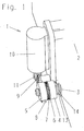
- Figur 1: Eine perspektivische Darstellung der erfindungsgemäßen Vorrichtung zum Umschalten eines mechanischen Schaltmittels nach einer ersten Ausführungsform im entkuppelten Zustand,
- Figur 2: Eine Schnittansicht der Vorrichtung zum Umschalten eines mechanischen Schaltmittels nach Figur 1,
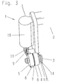
- Figur 3: Eine perspektivische Darstellung der erfindungsgemäßen Vorrichtung zum Umschalten eines mechanischen Schaltmittels nach der ersten Ausführungsform im gekuppelten Zustand,
- Figur 4: Eine perspektivische Darstellung der erfindungsgemäßen Vorrichtung zum Umschalten eines mechanischen Schaltmittels nach einer zweiten Ausführungsform im entkuppelten Zustand,
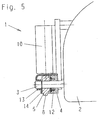
- Figur 5: Eine Schnittansicht der Vorrichtung zum Umschalten eines mechanischen Schaltmittels nach Figur 4 und
- Figur 6: Eine perspektivische Darstellung der erfindungsgemäßen Vorrichtung zum Umschalten eines mechanischen Schaltmittels nach der zweiten Ausführungsform im gekuppelten Zustand.
- Aus den Figuren 1 bis 3 ist eine erste Ausführungsform der erfindungsgemäßen Vorrichtung zum Umschalten eines mechanischen Schaltmittels ersichtlich, welche insgesamt mit dem Bezugszeichen 1 bezeichnet wird. Die Vorrichtung 1 zum Umschalten eines mechanischen Schaltmittels ist an einem Automatikgetriebe 2 vorgesehen und dient wenigstens zum Umschalten zwischen den vier Betriebsarten "P", "R", "N" und "D". Zwischen den unterschiedlichen Betriebsarten des Automatikgetriebes kann über das Verdrehen einer Welle 3 umgeschaltet werden, wobei von einer der Betriebsart "P" zugeordneten Winkelstellung der Welle 3 aus, diese in einer als positiv definierten Drehrichtung gedreht werden kann, um die anderen Betriebsarten "R", "N" und "D" einzuschalten. Dabei entsprechen die Betriebsarten "R", "N" und "D" in dieser Reihenfolge einer zunehmenden Verdrehung der Welle 3 in der positiven Drehrichtung.
- Ein als erste Zahnscheibe einer Zahnkupplung ausgebildetes Stellglied 4 ist konzentrisch zu und drehfest an der Welle 3 angeordnet. Ein als zweite Zahnscheibe der Zahnkupplung ausgebildetes Steuerglied 5 ist ebenfalls konzentrisch zu aber mit einem Spielsitz an der Welle 3 gelagert, wobei an den einander zugewandten Flächen der beiden Zahnscheiben jeweils ein zu der Welle konzentrischer Zahnkranz 6, 7 vorgesehen ist. Die Zähne des an dem Stellglied 4 angeordneten Zahnkranzes 6 stehen von dem Stellglied 4 in Richtung auf das Steuerglied 5 ab. Ferner stehen die Zähne des an dem Steuerglied 5 angeordneten Zahnkranzes 7 von dem Steuerglied 5 in Richtung auf das Stellglied 4 ab. Die Zahnkränze 6 und 7 haben den gleichen Durchmesser und sind derart ausgebildet, dass die Zähne des an dem Stellglied 4 angeordneten Zahnkranzes 6 in die Zwischenräume zwischen den Zähnen des an dem Steuerglied 5 angeordneten Zahnkranzes 7 eingreifen können und umgekehrt, wenn das Steuerglied 5 mit dem Stellglied 4 in Kontakt gebracht wird.
- Die geometrische Ausgestaltung der einzelnen Zähne der beiden Zahnkränze 6, 7 ist derart, dass durch die Übertragung eines Drehmomentes von dem Steuerglied 5 auf das Stellglied 4 oder umgekehrt eine Lösekraft hervorgerufen wird, welche an dem Steuerglied 5 angreift und dieses von dem Stellglied 4 wegdrückt. Wird der Lösekraft nicht eine Kuppelkraft entgegengesetzt, die das Steuerglied 5 auf das Stellglied 4 zudrückt, so wird bei ausreichend hoher Lösekraft das Steuerglied 5 von dem Stellglied 4 bis zu einer Position wegbewegt, in der die Zähne der beiden Zahnkränze 6, 7 nicht mehr ineinandergreifen. Ohne Kuppelkraft ist also keine drehfeste Verbindung zwischen dem Stellglied 4 und dem Steuerglied 5 vorhanden, wodurch der entkuppelte Zustand gekennzeichnet ist. Dies gilt auch, wenn zwar die Kuppelkraft vorhanden, aber vom Betrag her kleiner als die Lösekraft ist.
- Ist hingegen der Betrag der Kuppelkraft größer als der Betrag der Lösekraft, stehen das Stellglied 4 und das Steuerglied 5 miteinander in Kontakt. Die beiden Zahnkränze 6, 7 greifen ineinander und bilden eine drehfeste Verbindung zwischen dem Stellglied 4 und dem Steuerglied 5 aus, wodurch der gekuppelte Zustand gekennzeichnet ist.
- Das Steuerglied 5 weist an seinem Umfang eine Zahnreihe 8 mit radial ausgerichteten Zähnen auf, die einen Teil eines Kreisbogens bildet. In diese Zahnreihe 8 greift ein Zahnrad 9 ein, in welches eine über einen Motor 10 angetriebene Zylinderschnecke 11 eingreift. Die Zylinderschnecke 11 und das Zahnrad 9 bilden ein Schneckengetriebe mit Selbsthemmung, über welches das Steuerglied 5 von dem Motor 10 angetrieben bzw. gedreht werden kann. Der Motor 10, die Zylinderschnecke 11 und das Zahnrad 9 bilden in Zusammenwirkung mit der Zahnreihe 8 die Antriebsvorrichtung zum Antreiben des Steuergliedes 5.
- In dem Stellglied 4 ist ein Elektromagnet 12 vorgesehen, und das Steuerglied 5 ist aus ferromagnetischem Material hergestellt. Der Elektromagnet 12 und das ferromagnetische Material des Steuergliedes 5 bilden in Zusammenwirkung mit den Zahnkränzen 6, 7 eine Kuppelvorrichtung, mittels welcher das Stellglied 4 und das Steuerglied 5 miteinander gekuppelt werden können. Wird der Elektromagnet von einem elektrischen Strom durchflossen, so wird ein magnetisches Feld aufgebaut, welches das ferromagnetische Material magnetisiert und derart mit diesem zusammenwirkt, dass eine Kraft auf das ferromagnetische Material ausgeübt wird, welche als Kuppelkraft das Steuerglied 5 und das Stellglied 4 aneinanderstellt und fest zusammenhält. Wie aus Figur 3 ersichtlich, greifen dabei die beiden Zahnkränze 6, 7 ineinander, wodurch die drehfeste Verbindung zwischen dem Stellglied 4 und dem Steuerglied 5 ausgebildet wird. Das Stellglied 4 und das Steuerglied 5 befinden sich somit im gekuppelten Zustand, in welchem die von dem stromdurchflossenen Magneten in Zusammenwirkung mit dem ferromagnetischen Material hervorgerufene Kuppelkraft immer größer als die Lösekraft der Zahnkupplung ist.
- Im gekuppelten Zustand kann die Welle 3 von dem Motor 10 gedreht werden, so dass mit Hilfe des Motors 10 zwischen den unterschiedlichen Betriebsarten des Automatikgetriebes 2 umgeschaltet werden kann. Der Motor 10 wird dabei von einem nicht dargestellten elektronischen Schaltkreis derart angesteuert, dass die im Automatikgetriebe 2 eingeschaltete Betriebsart zu der Schaltstellung des Schalthebels in der Fahrgastkabine des Kraftfahrzeuges korrespondiert. Dafür kann die Welle 3 vom Motor 10 entweder in die positive oder in die negative Drehrichtung gedreht werden.
- An der dem Automatikgetriebe 2 zugewandten Fläche des Stellrades 4 ist eine Schenkelfeder 13 mit einem Ende befestigt, deren anderes Ende an einem an dem Automatikgetriebe 2 vorgesehenen Widerlager 14 befestigt ist.
- Die Schenkelfeder 13 ist derart zwischen dem Stellglied 4 und dem Widerlager 14 befestigt, dass sie in der Betriebsart "P" ihre geringste Spannung aufweist, welche nachfolgend als Vorspannung bezeichnet wird. Zum Einschalten der Betriebsarten "R", "N" und "D" wird die Welle 3 über das Stellglied 4 in positiver Drehrichtung gedreht, wobei die Schenkelfeder 13 über die Vorspannung hinaus zusätzlich gespannt wird. Die Arbeit zum zusätzlichen Spannen der Schenkelfeder wird dabei im gekuppelten Zustand vom Motor 10 aufgebracht.
- Kommt es nun in dem Fahrzeug zu einem Stromausfall, so bricht auch die Stromversorgung für den Elektromagneten 12 zusammen, und es wirkt keine Kuppelkraft mehr auf das Steuerglied 5. Ist das Automatikgetriebe 2 in einer anderen Betriebsart als der Betriebsart "P", so bewirkt das von der gespannten Schenkelfeder auf das Stellglied 4 übertragene Drehmoment, dass das Steuerglied 5 aufgrund der Lösekraft von dem Stellglied wegbewegt wird. Danach wird das Stellglied 4 von der Schenkelfeder 13 aufgrund Ihrer Spannung in die der Betriebsart "P" zugeordnete Winkelposition zurückgedreht, wodurch gleichzeitig das Automatikgetriebe 2 über die Welle 3 in die Betriebsart "P" zurückgeschaltet wird, in welcher die Parksperre eingeschaltet ist.
- Damit das Stellglied 4 von der Schenkelfeder 13 auch zurückgedreht werden kann, ist eine bestimmte Mindestspannung der Schenkelfeder 13 erforderlich, die als Rückstellspannung bezeichnet wird. Die Schenkelfeder 13 weist in jeder von "P" verschiedenen Betriebsart mindestens diese Rückstellspannung auf, um ein Einschalten der Parksperre des Automatikgetriebes 2 bei einem Stromausfall sicher gewährleisten zu können. Aus diesem Grund kann es erforderlich sein, die Schenkelfeder 13 bereits in der der Betriebsart "P" zugeordneten Winkelposition des Stellgliedes 4 mit einer bestimmten Mindestvorspannung zu beaufschlagen. Damit die Mindestvorspannung nicht abgebaut wird, wenn sich die Zahnkupplung im entkuppelten Zustand befindet, ist zum Beispiel ein Anschlag am Automatikgetriebe 2 und ein Stift am Stellglied 4 vorgesehen, welcher in der der Betriebsart "P" zugeordneten Winkelposition des Stellgliedes 4 an dem Anschlag anliegt. Der Stift und der Anschlag wirken dabei derart zusammen, dass das Stellglied 4 in der der Betriebsart "P" zugeordneten Winkelposition nicht weiter in die negative Drehrichtung gedreht werden kann. Damit ist ein Abbau der Mindestvorspannung sicher verhindert.
- Aus den Figuren 4 bis 6 ist eine zweite Ausführungsform der erfindungsgemäßen Vorrichtung zum Umschalten eines mechanischen Schaltmittels ersichtlich, wobei die für die Merkmale nach der zweiten Ausführungsform verwendeten Bezugszeichen mit den für dieselben oder ähnliche Merkmale verwendeten Bezugszeichen nach der ersten Ausführungsform übereinstimmen.
- Im wesentlichen stimmt die zweite Ausführungsform bis auf die Anordnung der Schenkelfeder 13 und des Widerlagers 14 in baulicher Hinsicht mit der ersten Ausführungsform überein. Allerdings können nach der zweiten Ausführungsform der Anschlag am Automatikgetriebe 2 und der Stift am Stellglied 4 entfallen.
- Wie aus den Figuren 4 bis 6 ersichtlich, ist nach der zweiten Ausführungsform die Schenkelfeder 13 zwischen dem Stellglied 4 und dem Steuerglied 5 angeordnet. Dabei ist das Widerlager 14 an dem Steuerglied 5 vorgesehen, so dass die Schenkelfeder 13 mit ihrem einen Ende an dem Stellglied 4 und mit ihrem anderen Ende an dem an dem Steuerglied 5 vorgesehenen Widerlager 14 befestigt ist.
- Die Schenkelfeder 13 ist derart zwischen dem Stellglied 4 und dem Widerlager 14 befestigt, dass sie im entkuppelten Zustand ihre geringste Spannung aufweist. Zum Umschalten zwischen den Betriebsarten, muss zunächst der gekuppelte Zustand zwischen dem Stellglied 4 und dem Steuerglied 5 hergestellt werden, was bevorzugt in der Schaltstellung "P" des Automatikgetriebes 2 erfolgt. Das Steuerrad 5 wird dafür von dem Motor 10 in der positiven Drehrichtung so lange gedreht, bis die Spannung der Schenkelfeder 13 der Rückstellspannung entspricht, wobei unter Rückstellspannung in diesem Fall die Spannung zu verstehen ist, die erforderlich, um das Automatikgetriebe 2 aus jeder von "P" verschiedenen Betriebsart heraus in die Betriebsart "P" zurückschalten zu können. Erst wenn die Spannung der Schenkelfeder 13 die Rückstellspannung erreicht hat, werden das Stellglied 4 und das Steuerglied 5 über den Elektromagneten 12 miteinander gekuppelt. Um ein mögliches Verdrehen der Welle 3 beim Spannen der Schenkelfeder 13 zu vermeiden, kann das Stellglied 4 während des Spannvorganges über eine Mechanik gegen ein Verdrehen gesichert sein, von der das Stellglied 4 nach dem Spannvorgang wieder freigegeben wird. Zum Einschalten der Betriebsarten "R", "N" und "D" aus der Betriebsart "P" heraus wird die Welle 3 dann von dem Motor 10 über die gekuppelte Zahnkupplung in positiver Drehrichtung gedreht, wobei die Spannung der Schenkelfeder 13 für alle Betriebsarten des Automatikgetriebes 2 konstant auf die Rückstellspannung festgelegt ist, solange der gekuppelte Zustand aufrechterhalten bleibt.
- Nach der zweiten Ausführungsform muss also im Gegensatz zur ersten Ausführungsform im gekuppelten Zustand für das Umschalten zwischen den Betriebsarten des Automatikgetriebes 2 vom Motor 10 keine zusätzliche Arbeit zum Spannen der Schenkelfeder 13 aufgebracht werden.
- Kommt es nun in dem Fahrzeug zu einem Stromausfall, so bricht auch die Stromversorgung für den Elektromagneten 12 zusammen, und auf das Steuerglied 5 wirkt keine Kuppelkraft mehr. Das von der bis zur Rückstellspannung gespannten Schenkelfeder 13 auf das Stellglied 4 übertragene Drehmoment bewirkt, dass das Steuerglied 5 aufgrund der Lösekraft von dem Stellglied wegbewegt wird. Anschließend wird das Stellglied 4 von der Schenkelfeder 13 aufgrund Ihrer Spannung in die der Betriebsart "P" zugeordnete Winkelposition zurückgedreht, wodurch gleichzeitig das Automatikgetriebe 2 über die Welle 3 in die Betriebsart "P" zurückgeschaltet wird, in welcher die Parksperre eingeschaltet ist.
- Damit das Stellglied 4 auch von der Schenkelfeder 13 zurückgedreht werden kann, ist im entkuppelten Zustand eine Festlegung des Steuergliedes 5 hinsichtlich einer Drehbewegung relativ zu dem Stellglied 4 erforderlich. Diese bei der ersten Ausführungsform nicht erforderliche Festlegung erfolgt durch das von der Zylinderschnecke 11 und dem Zahnrad 9 gebildete Schneckengetriebe, welches eine ausreichend hohe Selbsthemmung aufweist, um ein Verdrehen des Steuergliedes 5 aufgrund der Federspannung der Schenkelfeder 13 zu verhindern.
-
- 1
- Schaltvorrichtung
- 2
- Automatikgetriebe
- 3
- Welle
- 4
- Stellglied
- 5
- Steuerglied
- 6
- Zahnkranz am Stellglied
- 7
- Zahnkranz am Steuerglied
- 8
- Zahnreihe am Steuerglied
- 9
- Zahnrad
- 10
- Motor
- 11
- Zylinderschnecke
- 12
- Elektromagnet
- 13
- Schenkelfeder
- 14
- Widerlager
Claims (8)
- Vorrichtung (1) zum Umschalten eines mechanischen Schaltmittels zwischen einem ersten Schaltzustand und wenigstens einem zweiten Schaltzustand, insbesondere zum Ein- bzw. Ausschalten einer Parksperre für ein Automatikgetriebe (2), mit- einem mit dem Schaltmittel gekoppelten Stellglied (4) zum Umschalten zwischen den Schaltzuständen,- einem mit dem Stellglied (4) kuppelbaren Steuerglied (5),- einer über ein elektrisches Signal betätigbaren Kuppelvorrichtung (5, 6, 7, 12), mittels welcher das Stellglied (4) und das Steuerglied (5) miteinander kuppelbar sind und welche derart ausgelegt ist, dass im Falle des Ausfalls des elektrischen Signals das Stellglied (4) und das Steuerglied (5) voneinander entkuppelt sind,- einer mit dem Steuerglied (5) gekoppelten Antriebseinrichtung (8, 9, 10, 11) zum Antreiben des Steuergliedes (5) und- einem zum Schalten des Schaltmittels in den ersten Schaltzustand vorgesehenen Federmittel (13), welches mit dem Stellglied (4) und einem Widerlager (14) gekoppelt und im zweiten Schaltzustand hinsichtlich des Stellgliedes (4) derart gespannt ist, dass im entkuppelten Zustand das Schaltmittel über das Stellglied (4) von dem Federmittel (13) in den ersten Schaltzustand geschaltet wird,
dadurch gekennzeichnet, dass- das Stellglied (4) und das Schaltmittel über eine Welle (3) miteinander gekoppelt sind, das Stellglied (4) drehfest mit der Welle verbunden ist und das Schaltmittel über eine Drehbewegung der Welle (3) zwischen dem ersten und dem zweiten Schaltzustand umgeschaltet wird und- das Steuerglied (5) hinsichtlich der Welle (3) drehbar gelagert ist und das Stellglied (4) und das Steuerglied (5) im gekuppelten Zustand drehfest miteinander verbunden sind wobei das Stellglied (4) und das Steuerglied (5) mit jeweils einem Zahnkranz (6, 7) an den einander zugewandten Flächen eine Zahnkupplung ausbilden. - Vorrichtung nach Anspruch 1, wobei das Schaltmittel als Parksperre eines Automatikgetriebes ausgebildet ist, der erste Schaltzustand dem Zustand der eingeschalteten Parksperre entspricht und der zweite Schaltzustand dem Zustand der ausgeschalteten Parksperre entspricht.
- Vorrichtung nach einem der Ansprüche 1 oder 2, wobei das Federmittel (13) als Spiralfeder, Schenkelfeder oder schraubenförmig gewundene Biegefeder ausgebildet und mit einem Ende an dem Stellglied (4) und mit dem anderen Ende an dem Widerlager (14) befestigt ist.
- Vorrichtung nach einem der Ansprüche 2 bis 3, wobei das Widerlager (14) am Automatikgetriebe (2) oder an einem relativ zum Automatikgetriebe (2) festen Ort vorgesehen ist.
- Vorrichtung nach einem der Ansprüche 1 bis 4, wobei das Widerlager (14) an dem Steuerglied (5) vorgesehen ist.
- Vorrichtung nach einem der Ansprüche 1 bis 5, wobei die Kuppelvorrichtung (5, 6, 7, 12) sowohl am Stellglied (4) als auch am Steuerglied (5) jeweils einen magnetisierbaren Bereich aufweist und wenigstens einer der magnetisierbaren Bereiche von einem durch das elektrische Signal aktivierbaren Elektromagnet (12) gebildet ist.
- Vorrichtung nach einem der Ansprüche 1 bis 6, wobei die Antriebseinrichtung (8, 9, 10, 11) einen Motor (10) aufweist, der über ein Schneckengetriebe (9, 11) mit dem Steuerglied (5) zum Drehen desselben gekoppelt ist.
- Vorrichtung nach einem der Ansprüche 1 bis 7, wobei das elektrische Signal zum Annehmen des dem Ausfall des elektrischen Signals zugeordneten Signalzustands von einer Steuereinheit steuerbar ist.
Applications Claiming Priority (3)
| Application Number | Priority Date | Filing Date | Title |
|---|---|---|---|
| DE10044159A DE10044159B4 (de) | 2000-09-06 | 2000-09-06 | Vorrichtung zum Umschaltung eines mechanischen Schaltmittels zwischen einem ersten Schaltzustand und wenigstens einem zweiten Schaltzustand |
| DE10044159 | 2000-09-06 | ||
| PCT/DE2001/003385 WO2002021022A1 (de) | 2000-09-06 | 2001-09-05 | Vorrichtung zum umschalten eines mechanischen schaltmittels zwischen einem ersten schaltzustand und wenigstens einem zweiten schaltzustand |
Publications (2)
| Publication Number | Publication Date |
|---|---|
| EP1228328A1 EP1228328A1 (de) | 2002-08-07 |
| EP1228328B1 true EP1228328B1 (de) | 2006-01-04 |
Family
ID=7655345
Family Applications (1)
| Application Number | Title | Priority Date | Filing Date |
|---|---|---|---|
| EP01974002A Expired - Lifetime EP1228328B1 (de) | 2000-09-06 | 2001-09-05 | Vorrichtung zum umschalten eines mechanischen schaltmittels zwischen einem ersten schaltzustand und wenigstens einem zweiten schaltzustand |
Country Status (6)
| Country | Link |
|---|---|
| US (1) | US6688448B2 (de) |
| EP (1) | EP1228328B1 (de) |
| JP (1) | JP4431309B2 (de) |
| DE (1) | DE10044159B4 (de) |
| ES (1) | ES2253427T3 (de) |
| WO (1) | WO2002021022A1 (de) |
Cited By (3)
| Publication number | Priority date | Publication date | Assignee | Title |
|---|---|---|---|---|
| US8607657B2 (en) | 2008-03-26 | 2013-12-17 | Lemforder Electronic Gmbh | Actuation device with haptic emulation |
| DE102017103317A1 (de) | 2017-02-17 | 2018-08-23 | Dr. Ing. H.C. F. Porsche Aktiengesellschaft | Parksperre für ein Automatikgetriebe sowie Verfahren zum Betreiben einer solchen Parksperre |
| DE102019134730A1 (de) * | 2019-12-17 | 2021-06-17 | Schaeffler Technologies AG & Co. KG | Parksperre für ein Kraftfahrzeug |
Families Citing this family (18)
| Publication number | Priority date | Publication date | Assignee | Title |
|---|---|---|---|---|
| DE10212038B4 (de) * | 2002-03-19 | 2011-06-16 | Zf Friedrichshafen Ag | Parksperre |
| US7104151B2 (en) * | 2003-09-23 | 2006-09-12 | Jidosha Denki Kogyo Co., Ltd. | Two-wheel drive and four-wheel drive change-over apparatus and driving actuator therefor |
| FR2865164B1 (fr) * | 2004-01-15 | 2006-04-07 | Teleflex Automotive France Sa | Dispositif de commande d'une boite de vitesses, en particulier pour vehicule automobile |
| JP4361927B2 (ja) * | 2006-08-08 | 2009-11-11 | 株式会社デンソー | シフトバイワイヤシステム |
| DE102007058922B3 (de) * | 2007-12-05 | 2009-06-18 | Zf Friedrichshafen Ag | Betätigungseinrichtung mit Kulissenwelle |
| US9239108B2 (en) * | 2009-11-27 | 2016-01-19 | Stoneridge Control Devices, Inc. | Shift-by-wire transmission range selector system and actuator for the same |
| US8671745B2 (en) | 2010-11-29 | 2014-03-18 | Ford Global Tehnologies, LLC | Shift-by-wire default-to-park functional verification |
| US10208858B2 (en) | 2016-04-25 | 2019-02-19 | Continental Automotive Systems, Inc. | Internal electronic park actuator |
| IT201600082166A1 (it) | 2016-08-04 | 2018-02-04 | Oerlikon Graziano Spa | Gruppo attuatore per controllare la posizione angolare di un organo di comando, particolarmente per trasmissione di veicolo. |
| DE102016223554A1 (de) * | 2016-11-28 | 2018-05-30 | Zf Friedrichshafen Ag | Elektromechanische Aktorik |
| US10591055B2 (en) | 2017-01-09 | 2020-03-17 | Robert Bosch Llc | Actuator with auxiliary motor |
| US10605360B2 (en) | 2017-02-23 | 2020-03-31 | Robert Bosch Gmbh | Actuator with release and return mechanisms |
| JP6571221B2 (ja) * | 2018-01-30 | 2019-09-04 | 本田技研工業株式会社 | 車両のパーキング機構 |
| DE102018120116B3 (de) * | 2018-08-17 | 2019-12-12 | Knorr-Bremse Gesellschaft Mit Beschränkter Haftung | Zahnhaltebremse für eine Tür für ein Fahrzeug und Verfahren zum Betreiben einer Zahnhaltebremse |
| DE102019100300A1 (de) | 2019-01-08 | 2020-07-09 | Küster Holding GmbH | Parksperraktuator |
| DE102019001189B4 (de) | 2019-02-19 | 2020-10-01 | Daimler Ag | Parksperrensystem für ein Kraftfahrzeug |
| DE102019128563A1 (de) * | 2019-10-22 | 2021-04-22 | Fte Automotive Gmbh | Elektromechanischer Parksperrenaktuator |
| DE102019135309A1 (de) * | 2019-12-19 | 2021-06-24 | Valeo Siemens Eautomotive Germany Gmbh | Parksperrenaktuator, Parksperre, elektrische Antriebseinrichtung und Fahrzeug |
Family Cites Families (22)
| Publication number | Priority date | Publication date | Assignee | Title |
|---|---|---|---|---|
| GB837200A (en) * | 1955-07-08 | 1960-06-09 | Zahnradfabrik Friedrichshafen | Improvements in and relating to clutches |
| US3400797A (en) * | 1966-07-05 | 1968-09-10 | Bendix Corp | Electromagnetic clutch or brake with dual coils |
| US4291586A (en) | 1980-02-19 | 1981-09-29 | General Motors Corporation | Shift control mechanism for a countershaft transmission |
| JPS61207258A (ja) * | 1985-03-12 | 1986-09-13 | Nippon Denso Co Ltd | 車両用自動ブレ−キシステム |
| US4805472A (en) * | 1986-09-30 | 1989-02-21 | Aisin Seiki Kabushiki Kaisha | Rotary torque transmission apparatus for four-wheel drive vehicles |
| US4790204A (en) * | 1987-07-16 | 1988-12-13 | Automotive Products, Plc | Electric shift apparatus |
| GB2219637B (en) * | 1988-06-08 | 1992-05-06 | Mitsubishi Electric Corp | Electromagnetic clutch in motor-powered drive device |
| US5180959A (en) | 1991-08-08 | 1993-01-19 | Eaton Corporation | Electrically controlled shift actuator |
| US5180038A (en) * | 1992-01-24 | 1993-01-19 | Orscheln Co. | Electronically controlled parking brake system |
| JP2943547B2 (ja) * | 1992-12-21 | 1999-08-30 | トヨタ自動車株式会社 | シフトバイワイヤ自動変速機の制御装置 |
| JPH07277156A (ja) * | 1994-04-08 | 1995-10-24 | Sanyo Electric Co Ltd | 自走車両の駐車ブレーキ装置 |
| GB2290840A (en) * | 1994-06-01 | 1996-01-10 | Arthur Richard | Fail-safe brake actuation system |
| US5601162A (en) * | 1994-12-13 | 1997-02-11 | Orscheln Co. | Spring applied automative parking brake system |
| US5696679A (en) * | 1995-06-09 | 1997-12-09 | Ford Global Technologies, Inc. | Integrated electronic control of pawl-gear park function of an automatic transmission |
| DE19527893C1 (de) | 1995-07-29 | 1996-10-31 | Ford Werke Ag | Elektrische Schaltvorrichtung für Wechselgetriebe von Kraftfahrzeugen |
| US5827149A (en) * | 1996-07-30 | 1998-10-27 | Hi-Lex Corporation | Electrically operated park lock for automatic transmission |
| JP3635385B2 (ja) * | 1996-11-19 | 2005-04-06 | 愛知機械工業株式会社 | 歯車式変速機の自動変速装置 |
| US6016717A (en) * | 1998-05-18 | 2000-01-25 | Teleflex Incorporated | Helical cable actuator for shift by wire system |
| DE19834156A1 (de) | 1998-07-29 | 2000-02-03 | Zahnradfabrik Friedrichshafen | Parksperre, insbesondere für automatische Getriebe von Kraftfahrzeugen |
| JP4385413B2 (ja) * | 1998-08-26 | 2009-12-16 | アイシン精機株式会社 | 2輪・4輪駆動切換装置 |
| BR9915954B1 (pt) * | 1998-12-03 | 2012-01-10 | atuador energizado, e, tranca energizada | |
| US6332257B1 (en) * | 1999-04-30 | 2001-12-25 | Chrysler Corporation | Method of converting an existing vehicle powertrain to a hybrid powertrain system |
-
2000
- 2000-09-06 DE DE10044159A patent/DE10044159B4/de not_active Expired - Fee Related
-
2001
- 2001-09-05 US US10/111,720 patent/US6688448B2/en not_active Expired - Fee Related
- 2001-09-05 WO PCT/DE2001/003385 patent/WO2002021022A1/de active IP Right Grant
- 2001-09-05 EP EP01974002A patent/EP1228328B1/de not_active Expired - Lifetime
- 2001-09-05 JP JP2002525400A patent/JP4431309B2/ja not_active Expired - Fee Related
- 2001-09-05 ES ES01974002T patent/ES2253427T3/es not_active Expired - Lifetime
Cited By (8)
| Publication number | Priority date | Publication date | Assignee | Title |
|---|---|---|---|---|
| US8607657B2 (en) | 2008-03-26 | 2013-12-17 | Lemforder Electronic Gmbh | Actuation device with haptic emulation |
| DE102017103317A1 (de) | 2017-02-17 | 2018-08-23 | Dr. Ing. H.C. F. Porsche Aktiengesellschaft | Parksperre für ein Automatikgetriebe sowie Verfahren zum Betreiben einer solchen Parksperre |
| US10626990B2 (en) | 2017-02-17 | 2020-04-21 | Dr. Ing. H.C. F. Porsche Aktiengesellschaft | Parking lock for an automatic transmission and method for operating the parking lock |
| US10995856B2 (en) | 2017-02-17 | 2021-05-04 | Dr. Ing. H.C. F. Porsche Aktiengesellschaft | Parking lock for an automatic transmission and method for operating the parking lock |
| DE102019134730A1 (de) * | 2019-12-17 | 2021-06-17 | Schaeffler Technologies AG & Co. KG | Parksperre für ein Kraftfahrzeug |
| WO2021121484A1 (de) | 2019-12-17 | 2021-06-24 | Schaeffler Technologies AG & Co. KG | Parksperre für ein kraftfahrzeug und verfahren zum betreiben einer parksperre |
| DE102019134730B4 (de) | 2019-12-17 | 2021-11-18 | Schaeffler Technologies AG & Co. KG | Parksperre für ein Kraftfahrzeug |
| US11976725B2 (en) | 2019-12-17 | 2024-05-07 | Schaeffler Technologies AG & Co. KG | Parking lock for a motor vehicle and method for operating a parking lock |
Also Published As
| Publication number | Publication date |
|---|---|
| DE10044159A1 (de) | 2002-03-21 |
| ES2253427T3 (es) | 2006-06-01 |
| DE10044159B4 (de) | 2009-12-31 |
| EP1228328A1 (de) | 2002-08-07 |
| JP4431309B2 (ja) | 2010-03-10 |
| US6688448B2 (en) | 2004-02-10 |
| US20020148318A1 (en) | 2002-10-17 |
| WO2002021022A1 (de) | 2002-03-14 |
| JP2004508517A (ja) | 2004-03-18 |
Similar Documents
| Publication | Publication Date | Title |
|---|---|---|
| EP1228328B1 (de) | Vorrichtung zum umschalten eines mechanischen schaltmittels zwischen einem ersten schaltzustand und wenigstens einem zweiten schaltzustand | |
| EP1334297B1 (de) | Stellvorrichtung für ein einstellbares getriebe | |
| DE69913641T2 (de) | Schaltgabel mit eingebauten Nockenbetätigung | |
| EP1257752B1 (de) | Elektromagnetische schalteinrichtung | |
| DE19654729A1 (de) | Elektromotorische Bremsvorrichtung | |
| EP3446003B1 (de) | Aktuator und vorrichtung zum einlegen einer parksperre eines kraftfahrzeugautomatikgetriebes mit einem derartigen aktuator sowie ein damit ausgestattetes kraftfahrzeug | |
| DE19650526B4 (de) | Automatische Lenkvorrichtung | |
| DE19851670A1 (de) | Elektromechanische Radbremsvorrichtung | |
| DE102009017714A1 (de) | Lenkrad für ein Kraftfahrzeug mit Überlagerungslenkung | |
| DE3626822A1 (de) | Gangschaltungs- und kupplungsvorrichtung | |
| DE3015000A1 (de) | Kegelreibungskupplung | |
| DE10008278A1 (de) | Vorrichtung zur Leistungsübertragung/-unterbrechung | |
| EP0215790B1 (de) | Federanordnung an einer schaltkupplung | |
| DE102021124081A1 (de) | Ventilsteuervorrichtung für einen Kühlmittelkreislauf eines Kraftfahrzeugs | |
| EP1054180A2 (de) | Scheibenbremse mit Feststellbremsfunktion | |
| EP1520127B1 (de) | Getriebeschaltung | |
| WO2013182181A1 (de) | Parksperre für ein getriebe eines kraftwagens | |
| DE10115419B4 (de) | Magnetbremse für eine Getriebesperrvorrichtung und elektromechanisches Getriebesperrsystem | |
| DE102019207075B3 (de) | Parksperrensystem | |
| EP1310703B1 (de) | Linearantrieb | |
| WO2020169294A1 (de) | Parksperrensystem für ein kraftfahrzeug | |
| EP1915280A1 (de) | Getriebe für ein bremssystem und bremssystem | |
| DE102005055442B3 (de) | Elektromechanische Bremse mit Notöffnungseinrichtung | |
| DE10162561A1 (de) | Kupplung | |
| DE102021212784B3 (de) | Kombinierte Radbremse eines Fahrzeugs einschließlich Vorrichtung zur Betätigung von Betriebsbremse und Feststellbremse |
Legal Events
| Date | Code | Title | Description |
|---|---|---|---|
| PUAI | Public reference made under article 153(3) epc to a published international application that has entered the european phase |
Free format text: ORIGINAL CODE: 0009012 |
|
| 17P | Request for examination filed |
Effective date: 20020322 |
|
| AK | Designated contracting states |
Kind code of ref document: A1 Designated state(s): AT BE CH CY DE DK ES FI FR GB GR IE IT LI LU MC NL PT SE TR |
|
| RBV | Designated contracting states (corrected) |
Designated state(s): AT BE CH CY DE ES FR GB IT LI SE |
|
| 17Q | First examination report despatched |
Effective date: 20040714 |
|
| GRAP | Despatch of communication of intention to grant a patent |
Free format text: ORIGINAL CODE: EPIDOSNIGR1 |
|
| GRAS | Grant fee paid |
Free format text: ORIGINAL CODE: EPIDOSNIGR3 |
|
| RBV | Designated contracting states (corrected) |
Designated state(s): ES FR GB IT SE |
|
| REG | Reference to a national code |
Ref country code: DE Ref legal event code: 8566 |
|
| GRAA | (expected) grant |
Free format text: ORIGINAL CODE: 0009210 |
|
| AK | Designated contracting states |
Kind code of ref document: B1 Designated state(s): ES FR GB IT SE |
|
| REG | Reference to a national code |
Ref country code: GB Ref legal event code: FG4D Free format text: NOT ENGLISH |
|
| GBT | Gb: translation of ep patent filed (gb section 77(6)(a)/1977) |
Effective date: 20060206 |
|
| REG | Reference to a national code |
Ref country code: SE Ref legal event code: TRGR |
|
| REG | Reference to a national code |
Ref country code: ES Ref legal event code: FG2A Ref document number: 2253427 Country of ref document: ES Kind code of ref document: T3 |
|
| ET | Fr: translation filed | ||
| PLBE | No opposition filed within time limit |
Free format text: ORIGINAL CODE: 0009261 |
|
| STAA | Information on the status of an ep patent application or granted ep patent |
Free format text: STATUS: NO OPPOSITION FILED WITHIN TIME LIMIT |
|
| 26N | No opposition filed |
Effective date: 20061005 |
|
| PGFP | Annual fee paid to national office [announced via postgrant information from national office to epo] |
Ref country code: GB Payment date: 20090902 Year of fee payment: 9 Ref country code: SE Payment date: 20090910 Year of fee payment: 9 |
|
| PGFP | Annual fee paid to national office [announced via postgrant information from national office to epo] |
Ref country code: ES Payment date: 20091006 Year of fee payment: 9 |
|
| REG | Reference to a national code |
Ref country code: SE Ref legal event code: EUG |
|
| GBPC | Gb: european patent ceased through non-payment of renewal fee |
Effective date: 20100905 |
|
| PG25 | Lapsed in a contracting state [announced via postgrant information from national office to epo] |
Ref country code: GB Free format text: LAPSE BECAUSE OF NON-PAYMENT OF DUE FEES Effective date: 20100905 |
|
| REG | Reference to a national code |
Ref country code: ES Ref legal event code: FD2A Effective date: 20111019 |
|
| PG25 | Lapsed in a contracting state [announced via postgrant information from national office to epo] |
Ref country code: ES Free format text: LAPSE BECAUSE OF NON-PAYMENT OF DUE FEES Effective date: 20100906 |
|
| PGFP | Annual fee paid to national office [announced via postgrant information from national office to epo] |
Ref country code: FR Payment date: 20110922 Year of fee payment: 11 |
|
| PGFP | Annual fee paid to national office [announced via postgrant information from national office to epo] |
Ref country code: IT Payment date: 20110915 Year of fee payment: 11 |
|
| PG25 | Lapsed in a contracting state [announced via postgrant information from national office to epo] |
Ref country code: SE Free format text: LAPSE BECAUSE OF NON-PAYMENT OF DUE FEES Effective date: 20100906 |
|
| REG | Reference to a national code |
Ref country code: FR Ref legal event code: ST Effective date: 20130531 |
|
| PG25 | Lapsed in a contracting state [announced via postgrant information from national office to epo] |
Ref country code: IT Free format text: LAPSE BECAUSE OF NON-PAYMENT OF DUE FEES Effective date: 20120905 Ref country code: FR Free format text: LAPSE BECAUSE OF NON-PAYMENT OF DUE FEES Effective date: 20121001 |