EP1226765A2 - Method and apparatus for manufacturing multiple compartment filters - Google Patents
Method and apparatus for manufacturing multiple compartment filters Download PDFInfo
- Publication number
- EP1226765A2 EP1226765A2 EP01130104A EP01130104A EP1226765A2 EP 1226765 A2 EP1226765 A2 EP 1226765A2 EP 01130104 A EP01130104 A EP 01130104A EP 01130104 A EP01130104 A EP 01130104A EP 1226765 A2 EP1226765 A2 EP 1226765A2
- Authority
- EP
- European Patent Office
- Prior art keywords
- filter
- sleeve
- drum
- processing station
- sleeves
- Prior art date
- Legal status (The legal status is an assumption and is not a legal conclusion. Google has not performed a legal analysis and makes no representation as to the accuracy of the status listed.)
- Granted
Links
Images


Classifications
-
- A—HUMAN NECESSITIES
- A24—TOBACCO; CIGARS; CIGARETTES; SIMULATED SMOKING DEVICES; SMOKERS' REQUISITES
- A24C—MACHINES FOR MAKING CIGARS OR CIGARETTES
- A24C5/00—Making cigarettes; Making tipping materials for, or attaching filters or mouthpieces to, cigars or cigarettes
- A24C5/47—Attaching filters or mouthpieces to cigars or cigarettes, e.g. inserting filters into cigarettes or their mouthpieces
- A24C5/475—Attaching filters or mouthpieces to cigars or cigarettes, e.g. inserting filters into cigarettes or their mouthpieces adapted for composite filters
-
- A—HUMAN NECESSITIES
- A24—TOBACCO; CIGARS; CIGARETTES; SIMULATED SMOKING DEVICES; SMOKERS' REQUISITES
- A24D—CIGARS; CIGARETTES; TOBACCO SMOKE FILTERS; MOUTHPIECES FOR CIGARS OR CIGARETTES; MANUFACTURE OF TOBACCO SMOKE FILTERS OR MOUTHPIECES
- A24D3/00—Tobacco smoke filters, e.g. filter-tips, filtering inserts; Filters specially adapted for simulated smoking devices; Mouthpieces for cigars or cigarettes
- A24D3/02—Manufacture of tobacco smoke filters
- A24D3/0204—Preliminary operations before the filter rod forming process, e.g. crimping, blooming
- A24D3/0212—Applying additives to filter materials
- A24D3/0225—Applying additives to filter materials with solid additives, e.g. incorporation of a granular product
-
- A—HUMAN NECESSITIES
- A24—TOBACCO; CIGARS; CIGARETTES; SIMULATED SMOKING DEVICES; SMOKERS' REQUISITES
- A24D—CIGARS; CIGARETTES; TOBACCO SMOKE FILTERS; MOUTHPIECES FOR CIGARS OR CIGARETTES; MANUFACTURE OF TOBACCO SMOKE FILTERS OR MOUTHPIECES
- A24D3/00—Tobacco smoke filters, e.g. filter-tips, filtering inserts; Filters specially adapted for simulated smoking devices; Mouthpieces for cigars or cigarettes
- A24D3/02—Manufacture of tobacco smoke filters
- A24D3/0275—Manufacture of tobacco smoke filters for filters with special features
- A24D3/0287—Manufacture of tobacco smoke filters for filters with special features for composite filters
Definitions
- the invention relates to a method for producing Multiple filters and a device for manufacturing of multiple filters for tobacco processing products Industry, the device being a filter sleeve feed element, at least one transport element in which Filter sleeves can be inserted and by means of which Filter sleeves of at least one processing station are fed, includes.
- the invention further relates to the use of pre-assembled filter sleeves for Manufacture of multiple filters for tobacco processing products Industry, a corresponding filter sleeve for the production of multiple filters for products of tobacco processing industry and a multiple filter manufacturing system for tobacco processing products Industry that uses a filter cartridge feeder Feeding filter sleeves and a transport system to the Transporting the filter sleeves on a predeterminable Trajectory includes.
- Method and device for producing multiple filters are, for example, from DE-AS 17 82 364 of the applicant, the a device for producing filter granules containing filters with the name "Bernhard” der Applicant who is known in specialist circles describes.
- DE-AS 17 82 364 corresponds to GB 1,243,977 and US 3,603,058 multiple filters, also multi-segment filters are made up of at least two filter elements and typically up to eight filter elements, which can be in any order. In a sleeve formed into a tube will be different Filter elements or segments arranged.
- these can its soft filter elements, such as cellulose acetate, paper, Fleece or relatively hard filter elements such as granules, sintered elements, hollow cylinders or hollow chambers and Capsules and the like.
- the corresponding filter materials do not have to be 100% made of one material.
- This can for example also be mixed materials such as a Granules in a cellulose acetate.
- granular materials such as activated carbon.
- DE-AS 17 82 364 is a granule filling machine known filters containing granules and in particular Produces triple filters. Under triple filter is understood a filter that represents a filter that consists of there are three filter segments, the filling machine "Bernhard” a triple filter twice the working length manufactures, which then for cigarette production between two elongated ones wrapped in cigarette paper Articles containing tobacco are arranged to be in the Middle to be cut so that two with filters provided cigarettes arise.
- DE-AS 17 82 364 is a continuously rotating conveyor with recordings for filter sleeves disclosed, the filter sleeves transversely axially.
- filter plugs that last from a longer one Filter rod are cut off and granules in the Introduced sleeve.
- the filter plugs are transferred namely plunger, inserted into the sleeve.
- the granules fall under the influence of gravity in the sleeve.
- the inventive method it is possible Filter manufacturing speed of a filter manufacturing machine to increase significantly.
- the term “multiple filter” also includes the term “Multi-segment filter”, with at least two segments in the filter are included.
- the segments can be of different types Materials like cellulose acetate, Paper, fleece, granules, sintered elements, hollow cylinders or hollow chambers, capsules, etc.
- Invention will be at least two segments essentially formed simultaneously in the filter sleeve. It So this is the training of several Segments by transferring multiple servings of Filter material.
- the filter sleeve is in an insertion process fully filled or always in two portions or triple portions, in which preferably at the bottom a soft element, such as cellulose acetate, paper and the like. and a granulate or more another soft element is arranged above it.
- a final method step can also preferably be carried out be carried out in which only one Filter material in one portion in the filter sleeve is introduced.
- a Filter sleeve provided and / or manufactured.
- the filter sleeve is exclusively from one side filled, creating a simple design a corresponding device for the production of Multiple filters for tobacco processing products Industry is possible.
- the filling speed be further increased. This is preferred one half each with a filling step or in several filling steps in which packages, through which several segments are formed be filled up.
- the filter sleeve is preferably used to fill two Pages turned.
- the feed is Filter sleeve preferably designed such that in the A filter element is arranged in the middle. So it will preferably with a pre-assembled filter sleeve a filter element in the middle.
- the filter sleeve for filling on a Predeterminable trajectory at least partially transversely led, resulting in a quick procedure and simple constructive elements of a corresponding Have the furnishings implemented.
- the filter material is inserted with a vertical motion component.
- the filter sleeve is preferably formed in a preceding method step.
- the filter sleeve is preferably wrapping material sections or tubular wrappings formed into tubes.
- the filter material segments are or are preferably Filter material segments formed, the alternating granular material and, in particular gas-permeable, limiting pieces, such as soft elements made of cellulose acetate, paper or nonwoven or the like. exhibit.
- An n-fold multiple filter is preferably formed, where n is a natural even number that is greater than 1.
- An n-fold multiple filter means a filter n times the working length. So this is an n-fold multiple filter, where the "multiple" stands for several segments.
- a multiple filter is preferably according to one of the ones described above Process manufactured.
- the invention is further through a device for Manufacture of multiple filters for tobacco processing products
- a filter cartridge feeder and at least one transport element, in the filter sleeves can be inserted and by means of which Filter sleeves can be fed to at least one processing station are solved, which is further developed in that at least two in at least one processing station Portions of the filter materials in one processing step can be inserted into at least one filter sleeve. Preferably two portions can be inserted, if the servings in one processing station in more are insertable as a filter sleeve.
- Design of the facility for manufacturing of multiple filters is a very quick procedure possible.
- a rotating device for rotating the Filter sleeve provided as a processing station.
- the filling be done even faster because the movements, the feed or filling organs must carry out, can be kept relatively short.
- the at least one processing station on a single Arranged conveyor can be a very compact Furnishings can be realized.
- a modular structure is possible if the conveyors have at least one processing station assigned. If the sponsors maximum a processing station is assigned is a particularly modular structure of the facility.
- a plurality of conveyors are preferably provided, of which at least one at least one processing station is assigned, and of which at least one is only one Processing station is assigned.
- a filter material feed station is preferably provided, these two rotatable and eccentrically arranged Comprises disks, each having bores, the holes of one disc and the holes the other disc in one place can be aligned.
- this filter material feed station is a very accurate dosage of For example, filter granulate possible.
- At least one filter material feed station provided, these at least one sliding element, which is provided with holes, and / or at least one lever element provided with holes is included.
- this filter material feed station is a simple and quick handling of filter material possible.
- a particularly simple implementation of the invention Setup is given when a filter material loading station is provided, the at least one first transfer means, in particular at least one Tappet, which comprises at least two portions of the filter materials in one step in the filter sleeve brings.
- the filter material insertion station can preferably with a filter material feed station overlap.
- At least one second transfer means provided that from the opposite side the filter sleeve as a counter bearing to the at least one first transfer means acts.
- the transfer agent can even filter material into the filter sleeve introduce this does not necessarily have to.
- At least one filter sleeve with at least two holes can be aligned axially.
- the invention is further accomplished by a multiple filter manufacturing system for tobacco processing products Industry with a filter sleeve feeder for Feeding filter sleeves and a transport system to the Transporting the filter sleeves on a predeterminable Trajectory and at least one processing station solved, which is further developed in that in the at least one processing station in one processing step at least two servings of the filter material can be introduced into at least one filter sleeve.
- filter manufacturing system Provided portions of filter material in several filter sleeves be introduced or can be introduced preferably at least two servings of each Filter materials introduced or can be introduced.
- the filter manufacturing system further developed that as a processing station Rotating device provided for rotating the filter sleeves is.
- This preferred configuration of the filter production system can be a particularly fast procedure to be possible. If preferably that Transport system at least one continuously rotating Has conveyor, the filter sleeves axially is a particularly simple implementation of the Filter manufacturing system possible.
- the at least one processing station assigned to at least one sponsor is one modular design possible.
- a very compact filter manufacturing system is given if preferred a single conveyor is provided, at least a processing station is assigned.
- a special one A highly modular system is given when several sponsors are provided, each of which at most a processing station is assigned.
- the one manufactured and distributed by the applicant Filter manufacturing machine or device for manufacturing of multiple filters for tobacco processing products Industry provides approximately 1,200 double filters Length of use. With the device according to the invention it is possible to have 5,000 multiple filters in duplicate Manufacture working length. The advantage of the invention The solution is particularly clear.
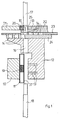
- FIG. 1 shows a cross-sectional illustration of a transfer station.
- a filter plug 20 which can consist, for example, of cellulose acetate.
- the filter plug 20 has a length of 8 mm, for example.
- the Filter plug 20 is by means of a filter plug conveyor 21, e.g. a filter plug drum, in which the Corresponding filter plugs 20 included in the recordings are fed to a plug receptacle 25.
- the filter sleeve 11 is engaged with the transfer station and is by means of vacuum bores 13, which are arranged on a conveyor drum in the specified Location held. It is also a plunger 18 from already been introduced into the filter sleeve 11 below. Furthermore, the plug 20 is through the filter plug conveyor 21 is conveyed to the transfer unit been and is by means of another vacuum drilling 13 held in the position shown in FIG. 2. Furthermore, two different granules, namely a first granulate 26 and a second granulate 27 in provided holes 14 of a slide 24 filled. The amount of granules is determined by the size of the hole given.
- the slider 24 is in the plane of the drawing from left to right to the right and vice versa.
- FIG. 3 shows a cross-sectional view of the transfer station
- the plunger 18 further up was moved vertically so that the sleeve 11 with its upper end essentially flush with the upper Edge of the conveyor drum 12 completes.
- the Stopper 20 by means of the plunger 17 in the axial direction the plunger, i.e. vertically downwards, into the pipe 15 and conveyed into a 1st bore 14 of the slide 23 Service.
- a circular knife 28, which in the guide 29th is cut exactly on the upper edge of the Slider 23 the plug 20 in two equally large plugs each with a length of 4 mm.
- a next process step which is shown in FIG is shown, the slide 23 is pushed to the left, so that the upper part of the split plug 20 with another bore 14 of the slide 23 vertically flees.
- the plug 20 by means of the plunger 17 transferred into the further hole and another Filter plug 30, which is made of a different material e.g. fleece enriched with granules, fed, cut by means of a circular knife and in the two remaining bores 14 of the slide 23 introduced.
- 5 shows exactly the state of the process shown in which the further filter plugs 30 in the remaining holes were introduced.
- the 1st Granules 26 fall into because of gravity Sleeve 11.
- the sleeve 11 will oscillate added.
- a vibration exciter 44 is provided, which causes a spring plate 43 to vibrate by mechanical contact of the spring plate 44 with the Sleeve 11 are transferred to this.
- FIG. 5 is a bore of the slide 23, in which is a filter plug 30 and a bore of the slide 24, in which granules are located, in alignment with the conveyor drum bore 16 or the sleeve 11 aligned so that in a next process step, which is shown in Fig. 6, the plunger 17th the filter material 30 and 26 in the filter sleeve 11 can introduce. It is possible instead, as in Fig. 6 was shown, the filter material 30 and 26 only up to introduce to the upper edge of the filter plug 11, so that the or the degree of movement of the plunger 17th have it minimized.
- FIG. 7 shows the process state in which after appropriate alignment, a hole, in which a filter plug 20 is arranged and a bore of the slide 24, in which the granules 27th is arranged, aligned with the sleeve 11 is so that the plunger 17 could insert the material.
- FIG. 8 shows the stage of the process in which the sleeve 11, half filled with filter material was moved down by lowering the plunger 18 was again in the effective range of the Vacuum bore 13, so that the sleeve 11 back to this Vacuum holes and corresponding to those in the conveyor drum 12 scheduled recordings is held.
- Next up Step is the half-filled sleeve of a turning drum fed to then the sleeve turned by 180 ° to undergo the same procedural steps so that a total of a five-fold filter twice the length of use can be manufactured.
- This quintuple filter includes then five different ones in this embodiment Filter materials in segments in the filter are arranged.
- first Filter material 19 for example a length of 8 mm
- Cutting the filter twice the length of use comprises a first granulate 26 with a height of approx. 8 mm, a second filter plug 30 with a height of 4 mm or a thickness of 4 mm, a second granulate 27 with a height of approx. 8 mm and a final one Filter plug 20 with a thickness of 4 mm.
- filter plugs from to use down to a thickness of 2 mm, so that even more filter materials in segments in the Filter sleeve 11 can be arranged.
- FIG. 8 shows a discharge drum 50, which conveys the half-filled sleeve 11 to a turning drum, which is not shown in Fig. 8.
- the sleeve is then turned through 180 ° in this turning drum turned and then by means of a feed drum Conveyor drum 12 is fed back to the rest of the sleeve 11 to fill.
- To produce filter material 19 can, for example Machine of the applicant, namely the Mulfi E accordingly can be set.
- PVA glue polyvinyl acetate glue
- the cooling bar that glues the seam is replaced by a Heating element replaced.
- the glue supply will also be appropriate replaced.
- the filter sleeve comes with a Glue stuck, which does not become detached by heating the glue connection leads.
- the segment bonding i.e. the gluing of the later inserted filter segments is done in such a way that a hot melt adhesive tape on the Paper is applied inside the sleeve, before the sleeve is molded.
- the entire sleeve warmed either by contact heat or with appropriate high-energy radiation, e.g. Microwave radiation, with which the hot melt adhesive for Melt is brought and the segments glued become.
- FIG. 9 shows a further embodiment according to the invention a transfer device in which at the same time transfer four different filter materials into the sleeve can be.
- the sleeve is, for example. from a paper tube 37.
- a third slide 41 and a fourth slide 42 is provided.
- a soft element 30 is inserted and a granulate 26 in the fourth slide 42.
- Number of holes in the slide 24 of the exemplary embodiments 1 to 8 to four, so that four holes are filled with the appropriate granulate and so that no further granulate filling after the It is necessary to turn or turn the filter sleeve.
- FIGS. 1 to 8 are already appropriate filter plugs 20 and 30 stocked so that after filling one side of the filter sleeve 11 none another filter plug inserted into the slider 23 Need to become. The same is of course also the case with Embodiment according to Fig. 9 possible.
- FIG. 10 is a side view in the upper region (FIG. 10b) a cross-sectional view of a granulate feed station or a granulate portioning station shown.
- a first disc 31 and a second Disc 32 shown, the first disc 31st is arranged above the second disc 32.
- 10b shows a top view of this device. Both disks, 31 and 32, have holes 14 on.
- Granules 26 are filled into the bores.
- the first disc 31 rotates counterclockwise over the disc 32, which in this embodiment is also counterclockwise rotates.
- On the second disc 32 are below this disc sleeves 11 arranged.
- a vibration exciter 44 and a Spring plate 43 is provided, by means of which the sleeve 11 when or after filling with the granules 26 in vibrations is transferred.
- the vibration exciter 44 is preferably an electromagnet with a mass with oscillates at a frequency of 50 Hz.
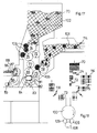
- FIG. 11 is a schematic plan view of a Filter manufacturing machine shown. It is in Fig. 11 but not the processing stations, which are shown in FIGS. 1 to 9, for example those responsible for inserting the filter elements are provided.
- a sleeve mass flow 101 carries sleeves 114 4 times the length of use to the filter manufacturing machine.
- the Filter sleeves cut 4 times the length of use in the middle and moved axially.
- a transfer cone drum 104 and a transfer drum 105 which e.g. 1 corresponds to the sleeve feed drum 10 the fed sleeves of the main drum 100, e.g. 1 corresponds to the conveyor drum 12.
- a filter element mass flow 102 carries filter elements 12 times the processing length of the filter manufacturing machine to. Some of these are not shown here cut into shorter sections.
- a Transfer cone drum 104 e.g. the filter plug conveyor 21 corresponds to FIG. 1, the filter elements or the already cut filter elements 116 fed to a transfer drum 105 on which it be further divided by means of a circular knife 106.
- a transfer drum 105 On which it be further divided by means of a circular knife 106.
- the granules are via appropriate conveying elements of a granulate transfer station 112 supplied, in the corresponding Drilling slide valves full of the desired granulate can be filled.
- the main drum 100 moves itself clockwise. Before finishing half one complete rotation of the main drum 100 is, for example. one side of a multiple filter with double working length been completely filled. This half-filled one Multiple filter is added by means of a transfer drum 109 a turning drum 108 conveyed to turn there and by means of a further transfer drum 109 to be fed to the main drum 100 again.
- the Turning drum 108 is for example in DE 199 20 760 A1 described by the applicant.
- the applicant is a device for turning rod-shaped objects described with a turning drum, the rod-shaped objects to be turned in recordings intended for this purpose.
- the turning drum has at least one turning section, the at least two rod-shaped objects to be turned turns parallel to each other.
- Heating element may be provided, which is in engagement with the appropriate sleeves can be brought to the hot-melt Glue in a previous process step attached to the inside of the paper tube was caused to stick, so that the brought Filter materials remain in their positions.
- the spring plate 43 is also shown in FIG serves to vibrate on filled with granules Transfer sleeves.
- Fig. 12 shows a schematic representation of a another embodiment of the invention.
- Filter sleeves 11 are one by means of a sleeve feed drum 10 Feed drum 12 supplied. This is at the position a) also shown schematically in FIG. 13.
- In b) move the sleeve 11 a little further up and the Ram 17 too.
- the plunger becomes wider move upwards.
- filter plugs 20 by means of a filter plug conveyor 21, which in this Embodiment is a drum supplied. This is also shown schematically in Fig. 13 at f).
- the plunger 17 moves into the Opening in which the sleeve 11 is located and brings the appropriate filter material into this sleeve.
- the plunger 17 moves out of this again Opening out.
- the lever moves back in his starting point.
- the sleeves 11 thus partially filled are removed by means of the removal drum 33.
- Filter sleeves with filter elements 34 are then located Filter sleeves with filter elements 34. It is also possible within the scope of this invention or this exemplary embodiment to fill an entire half of the sleeve 11. It is only the variant in FIGS. 12 and 13 a lever instead of a slide, be moved using the appropriate filter plug can. It is also possible to use several levers 35 in which granules are then introduced, for example can be, or a combination of levers and To use sliders.
- the core feed module thus includes a supply of sleeves from a sleeve collar 120, a take-off drum 123 and a transfer drum 124.
- the transfer drum 124 conveys the Sleeves from the take-off drum 123 to a discharge drum 125, which in turn turns the pods into a pellet drum 126 promoted. Arrived in the granule drum 126 granules are filled into the sleeves.
- the sleeves partially filled with granules are then transferred to a lever drum 127 which, for example. through a configuration according to 12 can be given can.
- this module namely in the granulate and soft element filler module 131 are slanted by a filter element 121 filter elements via a take-up drum 123 and a feed and sleeve removal drum 128 of the Lever drum 127 fed.
- the feed and sleeve removal drum 128 By means of the feed and sleeve removal drum 128 the with granules and appropriate filter elements such as Soft elements filled sleeves, one side of which is now in is fully filled from this embodiment and transferred to a transfer drum 124 which in the Wendermodul 132 is arranged.
- the transfer drum 124 passes the half-filled sleeves 11 to a turning drum 129, in which the sleeves are turned. On the way to The sleeves can be subjected to heat to activate a hot glue trail that the Filter elements fixed. After turning the pods the half-filled pods are further granulated and soft element filler module 131 and that by means of a delivery drum 125, which the sleeves one Granule drum 126 passes in the sleeves again be filled with granules.
- the Pass sleeves to a lever drum 127, in which the Sleeves are filled with another soft element.
- the soft elements are inclined by a filter element 121 via a take-off drum 123 and a feed and sleeve removal drum 128 of the lever drum 127 handed over.
- the sleeves are now fully filled then become a transfer drum via drum 128 124 passed on to a heating station 39 is arranged by means of, for example, a hot glue completely or activated in the remaining part of the sleeve can be.
- Double multiple filter 118 shown in longitudinal section, that of a first filter material 19, a granulate 26 and each composed of a filter plug 20 is.
- This double-multiple filter is used in the following Cigarette production in the middle of the first filter material 19 cut up.
- a filter manufacturing machine by means of of which a double multiple filter 118 can be manufactured can, which consists of four different filter elements twice the length of use.
- this double multiple filter 118 are two different types of granules 26 and 27 have been introduced.
- Another granulate are compared to the embodiment 14 shows two further granulate modules 133 for the filter manufacturing machine of Fig. 14 added. This lie between the sleeve feed module 130 and the Granule and soft element filler module 131 as well Wendermodul 132 and the further granulate and soft element filler module 131. Otherwise, the elements are the find use here, accordingly.
- the filter manufacturing concept is geared towards Filter plugs made of different filter materials and / or granules in changing composition in Introduce filter sleeves and to multi-segment filters or Process multiple filters.
- filter materials the term “granules”.
- Fig. 11 modified the filter sleeve is in a trough Carousels or the main drum 100 held and by Rotation of the main drum 100 from station to station forwarded.
- the stations are depending on the design of the filter, also in changing order, one Sleeve feed device, a granulate metering device with a granule feed station and a filter plug feed device, a filter turning device and again a granulate metering device with a Granule feed station and a filter plug feed device or just one granule feed station and one Filter plug device. Except when turning Sleeve always in the same place in the main drum 100 held.
- the sleeve is preferably vacuum or suction held in its position.
- the sleeve holder can For example, be provided with vibrations so that granules in the densest possible pack can.
- FIG. 16 schematically shows a further exemplary embodiment a transfer station for the transfer of filter elements in a sleeve 11 which is a first filter material includes.
- the sleeve 11 is in the state of the process 16 by means of vacuum bores 13 on the conveyor drum 12 held. To the sleeve 11 in the bore 16 of the To insert tube disk 62, this is by means of a Lower plunger 18, which is guided by a plunger guide 60 will move upwards.
- the lower plunger 18 is in Active connection with a lower control cam 68, the specifies how far up or down the lower plunger 18 is extended.
- the upper plunger 17 which in one Ram guide 61 is guided.
- the upper plunger 17 stands in operative connection with an upper cam 67, the specifies how far the upper plunger 17 down or to is extended at the top.
- 16 is the upper tappet 17 arranged in the top position.
- a first granulate 26 is already in the second slide 24 introduced in the intended recordings.
- Fig. 16 shows the state in which a second granulate 27, that of a granulate container 65 via a filler neck 66 in further shots of the second slide 24 is spent. So that the packing is as tight as possible or filling the second granulate 27 as densely as possible happens, a vibration exciter 44 is in operative connection provided with the filler neck 66.
- the vibration exciter 44 swings with one, for example Frequency of 50 Hz.
- This can be a Electromagnets with a corresponding moving Act mass so that corresponding vibrations are generated become.
- Fig. 17 shows an embodiment in which, for example a main drum 100 associated with the main drum 100 11 is somewhat varied, with filter elements or Filter material is supplied and as appropriate the main drum 100 manufactured double multiple filters 118 or double multi-segment filter 118 are discharged.
- the filter elements After cutting into two filter elements, double Usage length 72, the filter elements in one Relay drum 77 staggered, then a transfer drum / sliding drum 80 to be handed over.
- the filter elements are 2-fold Working length 72 arranged in front and the sleeves 2 times the usage length 115 arranged behind it, so that only the front filter elements 2 times the working length 72 are recognizable.
- the respective filter elements 72 and 115 then become a cone deflection drum 81 or 82 handed over, whereupon by handing over to a Transfer drum 83 and 84, the filter elements of the Main drum 100 are fed.
- the main drum 100 is not in this figure for clarity shown; however, it is schematic in FIG. 18 shown.
- Double-multiple filter 118 or multi-segment filter 118 taken over by a takeover drum 85 and one Cone deflection drum 86 supplied. Finally done a delivery to a delivery drum 87 which contains the multi-segment filter Deliver 118 to a mass flow 88. It are the multi-segment filter in this embodiment or double multiple filters 118 that have filter elements 73 at the end, then for In the middle, for example, a granulate filling having generated on the main drum 100 and in the middle the well-known filter plug or have the first filter material 19.
- FIGS. 17 and 18 There are thus three main functions in FIGS. 17 and 18, namely the supply of prefabricated sleeves 11 over a previously formed Mass flow, the supply of the filter elements, for example Soft filter elements with the help of appropriate Function groups as shown in the embodiment and the removal of the in the main drum 100 manufactured finished product via appropriate transport drums to form a new mass flow.
- the filter elements for example Soft filter elements with the help of appropriate Function groups as shown in the embodiment
Abstract
Description
Die Erfindung betrifft ein Verfahren zur Herstellung von Mehrfachfiltern sowie eine Einrichtung zur Herstellung von Mehrfachfiltern für Produkte der tabakverarbeitenden Industrie, wobei die Einrichtung ein Filterhülsenzuführelement, wenigstens ein Transportelement, in das Filterhülsen einbringbar sind und mittels dem die Filterhülsen wenigstens einer Bearbeitungsstation zuführbar sind, umfaßt. Die Erfindung betrifft ferner die Verwendung von vorkonfektionierten Filterhülsen zur Herstellung von Mehrfachfiltern für Produkte der tabakverarbeitenden Industrie, eine entsprechende Filterhülse für die Herstellung von Mehrfachfiltern für Produkte der tabakverarbeitenden Industrie und ein Mehrfachfilter-Herstellungssystem für Produkte der tabakverarbeitenden Industrie, das eine Filterhülsenzuführvorrichtung zum Zuführen von Filterhülsen und ein Transportsystem zum Transportieren der Filterhülsen auf einer vorgebbaren Bewegungsbahn umfaßt.The invention relates to a method for producing Multiple filters and a device for manufacturing of multiple filters for tobacco processing products Industry, the device being a filter sleeve feed element, at least one transport element in which Filter sleeves can be inserted and by means of which Filter sleeves of at least one processing station are fed, includes. The invention further relates to the use of pre-assembled filter sleeves for Manufacture of multiple filters for tobacco processing products Industry, a corresponding filter sleeve for the production of multiple filters for products of tobacco processing industry and a multiple filter manufacturing system for tobacco processing products Industry that uses a filter cartridge feeder Feeding filter sleeves and a transport system to the Transporting the filter sleeves on a predeterminable Trajectory includes.
Verfahren und Einrichtung zur Herstellung von Mehrfachfiltern sind bspw. aus der DE-AS 17 82 364 der Anmelderin, die eine Vorrichtung zum Herstellen von Filtergranulat enthaltenden Filtern mit dem Namen "Bernhard" der Anmelderin, die in Fachkreisen bekannt ist, beschreibt. Die DE-AS 17 82 364 entspricht der GB 1.243.977 und der US 3.603.058 Mehrfachfilter, auch Multisegment-Filter genannt werden, bestehen aus wenigstens zwei Filterelementen und typischerweise bis zu acht Filterelementen, die eine beliebige Reihenfolge aufweisen können. In einer zu einem Rohr geformten Hülse werden verschiedene Filterelemente bzw. -segmente angeordnet. Diese können sein Weichfilterelemente, wie Celluloseacetat, Papier, Vlies oder relativ harte Filterelemente wie Granulat, gesinterte Elemente, Hohlzylinder bzw. Hohlkammern und Kapseln und dgl. Die entsprechenden Filtermaterialien müssen nicht zu 100 % aus einem Material bestehen. Diese können bspw. auch Mischmaterialien sein wie bspw. ein Granulat in einem Celluloseacetat. Hierbei sei insbesondere an Granulatmaterialien wie Aktivkohle gedacht. Je nach verwendeten Materialien und der Filtersegmentreihenfolge ergeben sich die unterschiedlichsten Eigenschaften entsprechender Mehrfachfilter, die vorzugsweise endseitig an stabförmige Artikel der tabakverarbeitenden Industrie anbringbar sind.Method and device for producing multiple filters are, for example, from DE-AS 17 82 364 of the applicant, the a device for producing filter granules containing filters with the name "Bernhard" der Applicant who is known in specialist circles describes. DE-AS 17 82 364 corresponds to GB 1,243,977 and US 3,603,058 multiple filters, also multi-segment filters are made up of at least two filter elements and typically up to eight filter elements, which can be in any order. In a sleeve formed into a tube will be different Filter elements or segments arranged. these can its soft filter elements, such as cellulose acetate, paper, Fleece or relatively hard filter elements such as granules, sintered elements, hollow cylinders or hollow chambers and Capsules and the like. The corresponding filter materials do not have to be 100% made of one material. This can for example also be mixed materials such as a Granules in a cellulose acetate. Here in particular thought of granular materials such as activated carbon. Depending on the materials used and the filter segment order there are many different properties corresponding multiple filter, which preferably end of rod-shaped articles of the tobacco processing Industry are attachable.
Aus der DE-AS 17 82 364 ist eine Granulatfüllmaschine bekannt, die Granulat enthaltende Filter und insbesondere Dreifachfilter herstellt. Unter Dreifachfilter wird ein Filter verstanden, der ein Filter darstellt, der aus drei Filtersegmenten besteht, wobei die Füllmaschine "Bernhard" einen Dreifachfilter doppelter Gebrauchslänge herstellt, die dann für die Zigarettenproduktion zwischen zwei durch Zigarettenpapier umhüllte längliche Tabak enthaltende Artikel angeordnet werden, um in der Mitte durchgeschnitten zu werden, so daß zwei mit Filter versehene Zigaretten entstehen. In der DE-AS 17 82 364 ist ein kontinuierlich umlaufender Förderer mit Aufnahmen für Filterhülsen offenbart, der die Filterhülsen queraxial fördert. Während des queraxialen Förderns werden abwechselnd Filterstöpsel, die von einem längeren Filterstab abgeschnitten werden und Granulat in die Hülse eingebracht. Die Filterstöpsel werden mit Überführungsmitteln, nämlich Stößeln, in die Hülse eingebracht. Das Granulat fällt unter Schwerkrafteinwirkung in die Hülse.DE-AS 17 82 364 is a granule filling machine known filters containing granules and in particular Produces triple filters. Under triple filter is understood a filter that represents a filter that consists of there are three filter segments, the filling machine "Bernhard" a triple filter twice the working length manufactures, which then for cigarette production between two elongated ones wrapped in cigarette paper Articles containing tobacco are arranged to be in the Middle to be cut so that two with filters provided cigarettes arise. In DE-AS 17 82 364 is a continuously rotating conveyor with recordings for filter sleeves disclosed, the filter sleeves transversely axially. During cross-axial conveying are alternating filter plugs that last from a longer one Filter rod are cut off and granules in the Introduced sleeve. The filter plugs are transferred namely plunger, inserted into the sleeve. The granules fall under the influence of gravity in the sleeve.
Die relativ vielen Betätigungsschritte bei der Maschine "Bernhard", wobei insbesondere relativ weite Bewegungen ausgeführt werden müssen, führt zu einer Begrenzung der Leistungsfähigkeit der in der DE-AS 17 82 364 beschriebenen Granulat-Füllmaschine. Bei den immer höheren Leistungen von Zigarettenherstellmaschinen, ist es gewünscht, auch die Produktion von entsprechenden Filtern zu be-schleunigen. Es ist daher Aufgabe der vorliegenden Erfindung, ein Verfahren und eine Einrichtung sowie ein Mehrfachfilterherstellungssystem anzugeben, mittels dem die Produktionsmenge von Mehrfach-Filtern gesteigert wird.The relatively many operating steps on the machine "Bernhard", with relatively wide movements in particular must be carried out leads to a limitation of Performance of those described in DE-AS 17 82 364 Granule filling machine. With the ever higher performances of cigarette making machines, it is desirable also the production of appropriate filters to accelerate. It is therefore the task of the present Invention, a method and a device and a Specify multiple filter manufacturing system using the the production volume of multiple filters increased becomes.
Gelöst wird diese Aufgabe erfindungsgemäß durch ein Verfahren zur Herstellung von Mehrfachfiltern für Produkte der tabakverarbeitenden Industrie mit den folgenden Verfahrensschritten:
- Zuführen einer Filterhülse in eine vorgebbare Position und,
- Einführen von Filtermaterial in vorgebbaren Portionen, wobei wenigstens zwei Portionen der Filtermaterialien in einem Verfahrensschritt in die Filterhülse eingeführt werden.
- Feeding a filter sleeve into a predeterminable position and,
- Introducing filter material in predeterminable portions, at least two portions of the filter materials being introduced into the filter sleeve in one process step.
Durch das erfindungsgemäße Verfahren ist es möglich, die Filterherstellgeschwindigkeit einer Filterherstellmaschine deutlich zu erhöhen. Im Rahmen dieser Erfindung umfaßt der Begriff "Mehrfachfilter" auch den Begriff "Multisegmentfilter", wobei wenigstens zwei Segmente in dem Filter umfaßt sind. Die Segmente können aus verschiedenen Materialien bestehen, wie Celluloseacetat, Papier, Vlies, Granulat, gesinterte Elemente, Hohlzylinder bzw. Hohlkammern, Kapseln usw. Im Rahmen der Erfindung werden wenigstens zwei Segmente im wesentlichen gleichzeitig in der Filterhülse ausgebildet. Es handelt sich hierbei also um die Ausbildung von mehreren Segmenten durch Überführen von Mehrfach-Portionen von Filtermaterial. Vorzugsweise wird die Filterhülse in einem Einführvorgang voll befüllt oder immer in Zweierportionen bzw. Dreierportionen, bei denen vorzugsweise zuunterst ein Weichelement, wie Celluloseacetat, Papier und dgl. und darüber ein Granulat bzw. noch weiter darüber ein weiteres Weichelement angeordnet ist. Vorzugsweise kann auch ein abschließender Verfahrensschritt durchgeführt werden, bei dem nur ein einziges Filtermaterial in einer Portion in die Filterhülse eingeführt wird.The inventive method, it is possible Filter manufacturing speed of a filter manufacturing machine to increase significantly. Within the scope of this invention the term "multiple filter" also includes the term "Multi-segment filter", with at least two segments in the filter are included. The segments can be of different types Materials like cellulose acetate, Paper, fleece, granules, sintered elements, hollow cylinders or hollow chambers, capsules, etc. In the context of Invention will be at least two segments essentially formed simultaneously in the filter sleeve. It So this is the training of several Segments by transferring multiple servings of Filter material. Preferably, the filter sleeve is in an insertion process fully filled or always in two portions or triple portions, in which preferably at the bottom a soft element, such as cellulose acetate, paper and the like. and a granulate or more another soft element is arranged above it. A final method step can also preferably be carried out be carried out in which only one Filter material in one portion in the filter sleeve is introduced.
Vorzugsweise wird in einem ersten Verfahrensschritt eine Filterhülse zur Verfügung gestellt und/oder hergestellt. Vorzugsweise wird die Filterhülse ausschließlich von einer Seite befüllt, wodurch eine einfache Ausgestaltung einer entsprechenden Einrichtung zur Herstellung von Mehrfachfiltern für Produkte der tabakverarbeitenden Industrie möglich ist. Wenn vorzugsweise die Filterhülse von zwei Seiten befüllt wird, kann die Befüllungsgeschwindigkeit weiter erhöht werden. Hierbei wird vorzugsweise jeweils eine Hälfte mit einem Befüllschritt oder in mehreren Befüllschritten, bei denen Pakete, durch die mehrere Segmente ausgebildet werden, überführt werden, aufgefüllt.In a first method step, a Filter sleeve provided and / or manufactured. Preferably, the filter sleeve is exclusively from one side filled, creating a simple design a corresponding device for the production of Multiple filters for tobacco processing products Industry is possible. If preferably the filter sleeve filling from two sides, the filling speed be further increased. This is preferred one half each with a filling step or in several filling steps in which packages, through which several segments are formed be filled up.
Vorzugsweise wird die Filterhülse zum Befüllen von zwei Seiten gedreht. In diesem Fall ist die zugeführte Filterhülse vorzugsweise derart ausgestaltet, daß in der Mitte ein Filterelement angeordnet ist. Es wird somit vorzugsweise eine vorkonfektionierte Filterhülse mit einem Filterelement in der Mitte verwendet. Ferner vorzugsweise wird die Filterhülse zum Befüllen auf einer vorgebbaren Bewegungsbahn wenigstens teilweise queraxial geführt, wodurch sich eine schnelle Verfahrensführung und einfache konstruktive Elemente einer entsprechenden Einrichtung realisieren lassen. Ferner vorzugsweise geschieht das Einführen des Filtermaterials mit einer vertikalen Bewegungskomponente. Durch diese vorzugsweise Ausgestaltung der Erfindung sind kompakte Einrichtungen bzw. Filterherstellmaschinen realisierbar.The filter sleeve is preferably used to fill two Pages turned. In this case the feed is Filter sleeve preferably designed such that in the A filter element is arranged in the middle. So it will preferably with a pre-assembled filter sleeve a filter element in the middle. Further preferably the filter sleeve for filling on a Predeterminable trajectory at least partially transversely led, resulting in a quick procedure and simple constructive elements of a corresponding Have the furnishings implemented. Further preferably the filter material is inserted with a vertical motion component. By this preferably Embodiments of the invention are compact devices or filter manufacturing machines can be implemented.
Vorzugsweise wird die Filterhülse in einem vorangehenden
Verfahrensschritt ausgebildet. Bei der Filterhülse handelt
es sich vorzugsweise um zu Rohren geformte Umhüllungsmaterialabschnitte
bzw. rohrförmige Umhüllungen.
Vorzugsweise sind die Filtermaterial-Segmente bzw.
werden
Filtermaterial-Segmente ausgebildet, die abwechselnd
granulathaltiges Material und, insbesondere gasdurchlässige,
Begrenzungsstücke, wie Softelemente aus Celluloseacetat,
Papier oder Vlies o.ä. aufweisen. Vorzugsweise
wird ein n-fach-Mehrfachfilter ausgebildet, wobei n eine
natürliche gerade Zahl ist, die größer 1 ist. Mit einem
n-fach-Mehrfachfilter ist ein Filter n-facher Gebrauchslänge
gemeint. Es handelt sich hier also um ein n-fach-Mehrfachfilter,
wobei das "Mehrfach" für mehrere Segmente
steht.The filter sleeve is preferably formed in a preceding method step. The filter sleeve is preferably wrapping material sections or tubular wrappings formed into tubes. The filter material segments are or are preferably
Filter material segments formed, the alternating granular material and, in particular gas-permeable, limiting pieces, such as soft elements made of cellulose acetate, paper or nonwoven or the like. exhibit. An n-fold multiple filter is preferably formed, where n is a natural even number that is greater than 1. An n-fold multiple filter means a filter n times the working length. So this is an n-fold multiple filter, where the "multiple" stands for several segments.
Vorzugsweise ist ein Mehrfachfilter nach einem der vorbeschriebenen Verfahren hergestellt.A multiple filter is preferably according to one of the ones described above Process manufactured.
Die Erfindung wird ferner durch eine Einrichtung zur Herstellung von Mehrfachfiltern für Produkte der tabakverarbeitenden Industrie gelöst, die ein Filterhülsenzuführelement und wenigstens ein Transportelement, in das Filterhülsen einbringbar sind und mittels dem die Filterhülsen wenigstens einer Bearbeitungsstation zuführbar sind gelöst, die dadurch weitergebildet ist, daß in wenigstens einer Bearbeitungsstation wenigstens zwei Portionen der Filtermaterialien in einem Bearbeitungsschritt in wenigstens eine Filterhülse einführbar sind. Vorzugsweise sind jeweils zwei Portionen einführbar, wenn die Portionen in einer Bearbeitungsstation in mehr als eine Filterhülse einführbar sind. Durch die erfindungsgemäße Ausgestaltung der Einrichtung zur Herstellung von Mehrfachfiltern ist eine sehr schnelle Verfahrensführung möglich.The invention is further through a device for Manufacture of multiple filters for tobacco processing products Industry solved that a filter cartridge feeder and at least one transport element, in the filter sleeves can be inserted and by means of which Filter sleeves can be fed to at least one processing station are solved, which is further developed in that at least two in at least one processing station Portions of the filter materials in one processing step can be inserted into at least one filter sleeve. Preferably two portions can be inserted, if the servings in one processing station in more are insertable as a filter sleeve. By the invention Design of the facility for manufacturing of multiple filters is a very quick procedure possible.
Vorzugsweise ist eine Drehvorrichtung zum Drehen der Filterhülse als Bearbeitungsstation vorgesehen. Durch diese Ausgestaltung der Erfindung, kann die Befüllung noch schneller durchgeführt werden, da die Bewegungen, die Zuführ- bzw. Befüllungsorgane ausführen müssen, relativ kurz gehalten werden können. Preferably, a rotating device for rotating the Filter sleeve provided as a processing station. By this embodiment of the invention, the filling be done even faster because the movements, the feed or filling organs must carry out, can be kept relatively short.
Vorzugsweise ist das wenigstens eine Transportelement wenigstens ein kontinuierlich umlaufender Förderer, der die Filterhülsen queraxial fördert. Wenn vorzugsweise die wenigstens eine Bearbeitungsstation an einem einzigen Förderer angeordnet ist, kann eine sehr kompakte Einrichtung realisiert werden. Ein modularer Aufbau ist möglich, wenn den Förderern wenigstens eine Bearbeitungsstation zugeordnet ist. Sofern den Förderern maximal eine Bearbeitungsstation zugeordnet ist, ist ein besonders modularer Aufbau der Einrichtung gegeben.This is preferably at least one transport element at least one continuously circulating conveyor, the promotes the filter sleeves axially. If preferred the at least one processing station on a single Arranged conveyor can be a very compact Furnishings can be realized. A modular structure is possible if the conveyors have at least one processing station assigned. If the sponsors maximum a processing station is assigned is a particularly modular structure of the facility.
Vorzugsweise sind mehrere Förderer vorgesehen, von denen wenigstens einer wenigstens einer Bearbeitungsstation zugeordnet ist, und von denen wenigstens einer nur einer Bearbeitungsstation zugeordnet ist. Mit dieser vorzugsweisen Ausgestaltung der Erfindung ist ein guter Kompromiß zwischen einer kompakten Einrichtung und einer ausreichenden Modularität gegeben.A plurality of conveyors are preferably provided, of which at least one at least one processing station is assigned, and of which at least one is only one Processing station is assigned. With this preferential Embodiment of the invention is a good compromise between a compact facility and a sufficient one Modularity given.
Vorzugsweise ist eine Filtermaterial-Zuführstation vorgesehen, wobei diese zwei drehbare und azentrisch angeordnete Scheiben umfaßt, die jeweils Bohrungen aufweisen, wobei die Bohrungen der einen Scheibe und die Bohrungen der anderen Scheibe an einem Ort miteinander fluchtend anordbar sind. Mittels dieser Filtermaterial-Zuführstation ist eine sehr genaue Dosierung von bspw. Filtergranulat möglich.A filter material feed station is preferably provided, these two rotatable and eccentrically arranged Comprises disks, each having bores, the holes of one disc and the holes the other disc in one place can be aligned. By means of this filter material feed station is a very accurate dosage of For example, filter granulate possible.
Vorzugsweise ist wenigstens eine Filtermaterial-Zuführstation vorgesehen, wobei diese wenigstens ein Schiebeelement, das mit Bohrungen versehen ist, und / oder wenigstens ein Hebelelement, das mit Bohrungen versehen ist, umfaßt. Mittels dieser Filtermaterial-Zuführstation ist eine einfache und schnelle Handhabung von Filtermaterial möglich. Vorzugsweise sind die vorgenannten beiden Filtermaterial-Zuführstationen zu einer Filtermaterial-Zuführstation zusammengefügt, bei der dann verschiedene Zuführmethoden Verwendung finden können.Preferably there is at least one filter material feed station provided, these at least one sliding element, which is provided with holes, and / or at least one lever element provided with holes is included. By means of this filter material feed station is a simple and quick handling of filter material possible. Preferably the above are two filter material feed stations to a filter material feed station put together at the then different feeding methods can be used.
Eine besonders einfache Realisierung der erfindungsgemäßen Einrichtung ist dann gegeben, wenn eine Filtermaterial-Einbringstation vorgesehen ist, die wenigstens ein erstes Überführungsmittel, insbesondere wenigstens einen Stößel, umfaßt, das wenigstens zwei Portionen der Filtermaterialien in einem Verfahrensschritt in die Filterhülse einbringt. Die Filtermaterial-Einbringstation kann hierbei vorzugsweise mit einer Filtermaterial-Zuführstation überlappen.A particularly simple implementation of the invention Setup is given when a filter material loading station is provided, the at least one first transfer means, in particular at least one Tappet, which comprises at least two portions of the filter materials in one step in the filter sleeve brings. The filter material insertion station can preferably with a filter material feed station overlap.
Vorzugsweise ist wenigstens ein zweites Überführungsmittel vorgesehen, das von der entgegengesetzten Seite der Filterhülse als Gegenlager zu dem wenigstens einen ersten Überführungsmittel fungiert. Das Überführungsmittel kann auch selbst Filtermaterial in die Filterhülse einführen, muß dieses allerdings nicht notwendigerweise.Preferably at least one second transfer means provided that from the opposite side the filter sleeve as a counter bearing to the at least one first transfer means acts. The transfer agent can even filter material into the filter sleeve introduce this does not necessarily have to.
Vorzugsweise ist wenigstens eine Filterhülse mit wenigstens zwei Bohrungen axial fluchtend anordbar.Preferably at least one filter sleeve with at least two holes can be aligned axially.
Die Erfindung wird ferner durch ein Mehrfachfilterherstellungssystem für Produkte der tabakverarbeitenden Industrie mit einer Filterhülsen-Zuführvorrichtung zum Zuführen von Filterhülsen und einem Transportsystem zum Transportieren der Filterhülsen auf einer vorgebbaren Bewegungsbahn und wenigstens einer Bearbeitungsstation gelöst, die dadurch weitergebildet ist, daß in der wenigstens einen Bearbeitungsstation in einem Bearbeitungsschritt wenigstens zwei Portionen des Filtermaterials in wenigstens eine Filterhülse einbringbar sind. The invention is further accomplished by a multiple filter manufacturing system for tobacco processing products Industry with a filter sleeve feeder for Feeding filter sleeves and a transport system to the Transporting the filter sleeves on a predeterminable Trajectory and at least one processing station solved, which is further developed in that in the at least one processing station in one processing step at least two servings of the filter material can be introduced into at least one filter sleeve.
Sofern Portionen von Filtermaterial in mehrere Filterhülsen eingebracht werden bzw. einbringbar sind, werden vorzugsweise jeweils wenigstens zwei Portionen der Filtermaterialien eingebracht bzw. sind diese einbringbar. Vorzugsweise ist das Filterherstellungssystem dadurch weitergebildet, daß als Bearbeitungsstation eine Drehvorrichtung zum Drehen der Filterhülsen vorgesehen ist. Durch diese vorzugsweise Ausgestaltung des Filterherstellungssystems, kann eine besonders schnelle Verfahrensführung möglich sein. Wenn vorzugsweise das Transportsystem wenigstens einen kontinuierlich umlaufenden Förderer aufweist, der die Filterhülsen queraxial fördert, ist eine besonders einfache Realisierung des Filterherstellungssystems möglich.Provided portions of filter material in several filter sleeves be introduced or can be introduced preferably at least two servings of each Filter materials introduced or can be introduced. Preferably, the filter manufacturing system further developed that as a processing station Rotating device provided for rotating the filter sleeves is. This preferred configuration of the filter production system can be a particularly fast procedure to be possible. If preferably that Transport system at least one continuously rotating Has conveyor, the filter sleeves axially is a particularly simple implementation of the Filter manufacturing system possible.
Wenn vorzugsweise die wenigstens eine Bearbeitungsstation wenigstens einem Förderer zugeordnet ist, ist eine modulare Bauweise möglich. Ein sehr kompaktes Filterherstellungssystem ist dann gegeben, wenn vorzugsweise ein einziger Förderer vorgesehen ist, dem wenigstens eine Bearbeitungsstation zugeordnet ist. Ein besonders hochgradig modulares System ist dann gegeben, wenn mehrere Förderer vorgesehen sind, denen jeweils höchstens eine Bearbeitungsstation zugeordnet ist.If preferably the at least one processing station assigned to at least one sponsor is one modular design possible. A very compact filter manufacturing system is given if preferred a single conveyor is provided, at least a processing station is assigned. A special one A highly modular system is given when several sponsors are provided, each of which at most a processing station is assigned.
Die von der Anmelderin hergestellte und vertriebene Filterherstellmaschine bzw. Einrichtung zur Herstellung von Mehrfachfiltern für Produkte der tabakverarbeitenden Industrie stellt ca. 1.200 Mehrfachfilter doppelter Gebrauchslänge her. Mit der erfindungsgemäßen Einrichtung ist es möglich, 5.000 Mehrfachfilter in doppelter Gebrauchslänge herzustellen. Der Vorteil der erfindungsgemäßen Lösung ist damit besonders klar. The one manufactured and distributed by the applicant Filter manufacturing machine or device for manufacturing of multiple filters for tobacco processing products Industry provides approximately 1,200 double filters Length of use. With the device according to the invention it is possible to have 5,000 multiple filters in duplicate Manufacture working length. The advantage of the invention The solution is particularly clear.
Die Erfindung wird nachstehend ohne Beschränkung des allgemeinen Erfindungsgedankens anhand von Ausführungsbeispielen beschrieben, auf die bezüglich aller im Text nicht näher erläuterten erfindungsgemäßen Einzelheiten ausdrücklich verwiesen wird. Es zeigen:
- Fig. 1
- eine Schnittdarstellung einer Übergabestation in einem ersten Verfahrensstadium,
- Fig. 2
- die Übergabestation aus Fig. 1 in einem weiteren Verfahrensstadium,
- Fig. 3 bis Fig. 8
- die Übergabestation aus Fig. 1 und 2 in fortlaufenden Verfahrensstadien,
- Fig. 9
- eine weitere erfindungsgemäße Ausführungsform einer Übergabestation,
- Fig. 10
- ein Granulat-Zuführelement in Seitenansicht (Fig. 10a) und in Aufsicht (Fig. 10b),
- Fig. 11
- eine schematische Darstellung einer Filterherstellmaschine in Aufsicht,
- Fig. 12
- eine schematische Aufsicht auf Elemente einer weiteren Filterherstellmaschine,
- Fig. 13
- schematisch die jeweilige Anordnung bzw. Lage von einer Filterhülse und einem Filterelement sowie einem entsprechenden Stößel in fortlaufender Bearbeitung,
- Fig. 14
- linke Seite: ein Dreifachfilter doppelter
Gebrauchslänge,
rechte Seite: eine schematische Darstellung einer modular aufgebauten Filterherstellmaschine, mit der der links dargestellte Filter herstellbar ist, - Fig. 15
- links: ein Vierfachfilter doppelter Gebrauchslänge, und rechts: eine schematische Darstellung einer Filterherstellmaschine, mit der der links dargestellte Filter herstellbar ist.
- Fig. 16
- eine Schnittdarstellung einer weiteren Ausführungsform einer Übergabestation mit im Vergleich zu dem Ausführungsbeispiel der Figuren 1 - 8 weiteren Merkmalen,
- Fig. 17
- eine schematische Seitenansicht von Funktionselementen zur Zufuhr von Filtermaterial und zur Entnahme von Multisegmentfiltern bzw. Mehrfachfiltern in einem Ausführungsbeispiel, und
- Fig. 18
- eine schematische Darstellung der Filterelemente im Verlauf der Bearbeitung gemäß der Fig. 17.
- Fig. 1
- 3 shows a sectional illustration of a transfer station in a first process stage,
- Fig. 2
- 1 in a further process stage,
- 3 to 8
- 1 and 2 in continuous process stages,
- Fig. 9
- another embodiment of a transfer station according to the invention,
- Fig. 10
- a granulate feed element in side view (Fig. 10a) and in plan view (Fig. 10b),
- Fig. 11
- 1 shows a schematic illustration of a filter manufacturing machine in supervision,
- Fig. 12
- 1 shows a schematic top view of elements of a further filter manufacturing machine,
- Fig. 13
- schematically the respective arrangement or location of a filter sleeve and a filter element and a corresponding plunger in continuous processing,
- Fig. 14
- left side: a triple filter twice the working length,
right side: a schematic representation of a modular filter manufacturing machine with which the filter shown on the left can be produced, - Fig. 15
- left: a quadruple filter twice the working length, and right: a schematic representation of a filter manufacturing machine with which the filter shown on the left can be produced.
- Fig. 16
- 3 shows a sectional illustration of a further embodiment of a transfer station with further features in comparison to the exemplary embodiment in FIGS. 1-8,
- Fig. 17
- is a schematic side view of functional elements for the supply of filter material and for the removal of multi-segment filters or multiple filters in one embodiment, and
- Fig. 18
- a schematic representation of the filter elements in the course of processing according to FIG. 17.
In den folgenden Figuren sind die gleichen Bezugszeichen für gleiche bzw. entsprechende Merkmale verwendet worden, so daß von einer erneuten Vorstellung jeweils abgesehen wird.The same reference numerals are used in the following figures have been used for the same or corresponding characteristics, so that apart from a renewed presentation becomes.
Fig. 1 zeigt eine Querschnittsdarstellung einer Übergabestation.
Eine in einer Mulde einer Hülsenzuführtrommel
10 angeordnete Hülse 11, die ein erstes Filtermaterial
19 mittig aufweist, wird in den Bereich einer Übergabestation
gebracht. Entsprechendes gilt für einen Filterstöpsel
20, der bspw. aus Celluloseacetat bestehen kann.
Der Filterstöpsel 20 hat bspw. eine Länge von 8 mm. Der
Filterstöpsel 20 wird mittels eines Filterstöpsel-Förderers
21, z.B. einer Filterstöpseltrommel, bei der die
entsprechenden Filterstöpsel 20 in Aufnahmen aufgenommen
sind, einer Stöpselaufnahme 25 zugeführt.1 shows a cross-sectional illustration of a transfer station.
One in a trough of a
In einem fortlaufenden Verfahrensschritt, der in Fig. 2
dargestellt ist, ist die Filterhülse 11 in Eingriff mit
der Übergabestation und wird mittels Vakuumbohrungen 13,
die an einer Fördertrommel angeordnet sind, in der angegebenen
Lage gehalten. Es ist ferner ein Stößel 18 von
unten schon in die Filterhülse 11 eingebracht worden.
Ferner ist der Stöpsel 20, der durch den Filterstöpselförderer
21 befördert wird, in die Übergabeeinheit übergeben
worden und wird mittels einer weiteren Vakuumbohrung
13 in der angezeigten Position in der Fig. 2 gehalten.
Ferner werden zwei verschiedene Granulate, nämlich
ein erstes Granulat 26 und ein zweites Granulat 27 in
dafür vorgesehene Bohrungen 14 eines Schiebers 24 gefüllt.
Die Menge des Granulats ist durch die Bohrungsgröße
gegeben.In a continuous process step, which is shown in FIG
is shown, the
Der Schieber 24 ist in der Zeichenebene von links nach
rechts und umgekehrt verschiebbar ausgestaltet.The
Fig. 3 zeigt eine Querschnittsdarstellung der Überführungsstation,
wobei der Stößel 18 weiter nach oben
vertikal bewegt wurde, so daß die Hülse 11 mit dessen
oberem Ende im wesentlichen fluchtend mit der oberen
Kante der Fördertrommel 12 abschließt. Ferner ist der
Stöpsel 20 mittels des Stößels 17 in axialer Richtung
des Stößels, also vertikal nach unten, in das Rohr 15
und in eine 1. Bohrung 14 des Schiebers 23 befördert
worden. Ein Kreismesser 28, das in der Führung 29
geführt ist, zerschneidet genau an der oberen Kante des
Schiebers 23 den Stöpsel 20 in zwei gleich große Stöpsel
mit jeweils 4 mm Länge. Zum Befördern des Stöpsels 20 in
das Rohr 15 und der Hülse 11 in die Fördertrommelbohrung
16 wird das Vakuum bzw. die Saugluft in den Vakuumbohrungen
13 abgestellt.3 shows a cross-sectional view of the transfer station,
the
In einem nächsten Verfahrensschritt, der in Fig. 4
dargestellt ist, wird der Schieber 23 nach links geschoben,
so daß der obere Teil des geteilten Stöpsels 20
mit einer weiteren Bohrung 14 des Schiebers 23 vertikal
fluchtet. In einem weiteren Verfahrensschritt, der nicht
dargestellt ist, wird der Stöpsel 20 mittels des Stößels
17 in die weitere Bohrung überführt und ein weiterer
Filterstöpsel 30, der aus einem anderen Material wie
bspw. Vlies, das mit einem Granulat angereichert ist,
zugeführt, mittels eines Kreismessers geschnitten und in
die beiden verbleibenden Bohrungen 14 des Schiebers 23
eingeführt. In Fig. 5 ist genau der Verfahrenszustand
dargestellt, in dem die weiteren Filterstöpsel 30 in die
verbleibenden Bohrungen eingeführt wurden. Das 1.
Granulat 26 fällt schon aufgrund der Schwerkraft in die
Hülse 11. Um eine möglichst dichte Befüllung zu erreichen,
wird die Hülse 11 in Schwingungen bzw. Vibrationen
versetzt. Hierzu ist ein Schwingungserreger 44 vorgesehen,
der ein Federblech 43 in Schwingungen versetzt, die
durch mechanischen Kontakt des Federblechs 44 mit der
Hülse 11 auf diese übertragen werden.In a next process step, which is shown in FIG
is shown, the
In Fig. 5 ist ferner eine Bohrung des Schiebers 23, in
dem sich ein Filterstöpsel 30 befindet und eine Bohrung
des Schiebers 24, in dem sich Granulat befindet, fluchtend
mit der Fördertrommelbohrung 16 bzw. der Hülse 11
ausgerichtet, so daß in einem nächsten Verfahrensschritt,
der in Fig. 6 dargestellt ist, der Stößel 17
das Filtermaterial 30 und 26 in die Filterhülse 11
einführen kann. Es ist möglich, anstelle, wie in Fig. 6
dargestellt wurde, das Filtermaterial 30 und 26 nur bis
zur oberen Kante des Filterstöpsels 11 einzuführen, so
daß sich die bzw. der Grad der Bewegung des Stößels 17
noch minimieren lassen.5 is a bore of the
In Fig. 7 ist der Verfahrenszustand dargestellt, in dem
nach entsprechender fluchtender Ausrichtung eine Bohrung,
in der ein Filterstöpsel 20 angeordnet ist und
eine Bohrung des Schiebers 24, in dem das Granulat 27
angeordnet ist, fluchtend mit der Hülse 11 ausgerichtet
ist, so daß der Stößel 17 das Material einführen konnte.7 shows the process state in which
after appropriate alignment, a hole,
in which a
In Fig. 8 ist das Verfahrensstadium dargestellt, in dem
die Hülse 11, die zur Hälfte mit Filtermaterial befüllt
wurde, durch Absenken des Stößels 18 nach unten befördert
wurde und zwar wieder in den Wirkbereich der
Vakuumbohrung 13, so daß die Hülse 11 wieder an diesen
Vakuumbohrungen und entsprechend den in der Fördertrommel
12 vorgesehenen Aufnahmen gehalten wird. Als nächster
Schritt wird die halbgefüllte Hülse einer Wendetrommel
zugeführt, um dann die um 180° gewendete Hülse
den gleichen Verfahrensschritten zu unterziehen, so daß
insgesamt ein Fünffach-Filter doppelter Gebrauchslänge
hergestellt werden kann. Dieser Fünffach-Filter umfaßt
dann in diesem Ausführungsbeispiel fünf verschiedene
Filtermaterialien, die in Segmenten in dem Filter
angeordnet sind. Es handelt sich hierbei um ein erstes
Filtermaterial 19, das bspw. eine Länge von 8 mm nach
Durchschneiden des Filters doppelter Gebrauchslänge
aufweist, ein erstes Granulat 26 mit einer Höhe von ca.
8 mm, einen zweiten Filterstöpsel 30 mit einer Höhe von
4 mm bzw. einer Dicke von 4 mm, ein zweites Granulat 27
mit einer Höhe von ca. 8 mm und einen abschließenden
Filterstöpsel 20 mit einer Dicke von 4 mm. Im Rahmen
dieser Erfindung ist es auch möglich, Filterstöpsel von
bis hinunter zu einer Dicke von 2 mm zu verwenden, so
daß auch noch mehr Filtermaterialien in Segmenten in der
Filterhülse 11 angeordnet werden können.8 shows the stage of the process in which
the
In Fig. 8 ist noch eine Abführtrommel 50 dargestellt,
die die halbbefüllte Hülse 11 abfördert und zwar zu
einer Wendetrommel, die in Fig. 8 nicht dargestellt ist.
In dieser Wendetrommel wird die Hülse dann um 180°
gewendet und dann mittels einer Zuführtrommel der
Fördertrommel 12 wieder zugeführt, um den Rest der Hülse
11 zu befüllen.8 shows a
Im Rahmen dieser Erfindung ist es auch möglich, die
Hülsen mehrfach zu wenden, um an mehreren Stationen
verschiedene Filtermaterialien einzubringen. Es muß also
nicht notwendigerweise jede Hälfte der Hülse 11 in einer
Übergabestation voll befüllt werden, bevor diese gedreht
wird.In the context of this invention, it is also possible
Sleeves to be turned several times to reach several stations
different filter materials. So it has to
not necessarily every half of the
Um die Hülsen 11 mit einem mittig angeordneten ersten
Filtermaterial 19 herzustellen, kann beispielsweise eine
Maschine der Anmelderin, nämlich die Mulfi E entsprechend
eingestellt werden. Um die später eingeführten
Filterstöpsel nachträglich verkleben zu können, wird die
Nahtverklebung der Hülse 11 von einem Heißschmelz-Kleber
auf PVA-Leim (Polyvinylacetat-Leim) umgestellt. Hierzu
wird der Kühlsteg, der die Naht verklebt, durch einen
Heizsteg ersetzt. Die Leimversorgung wird auch entsprechend
ausgetauscht. Die Filterhülse wird also mit einem
Leim verklebt, der nicht durch Erhitzung zu einem Lösen
der Leimverbindung führt. Around the
Die Segmentverklebung, d.h. die Verklebung der nachträglich eingefügten Filtersegmente geschieht dergestalt, daß ein heißschmelzender Klebestreifen auf das Papier aufgetragen wird und zwar innerhalb der Hülse, bevor die Hülse geformt wird. Nach dem Einfügen der Filtersegmente in die Hülse, die eine erkaltete Heißschmelzkleberspur aufweist, wird die gesamte Hülse erwärmt und zwar entweder durch Kontaktwärme oder mit entsprechender energiereicher Strahlung, wie z.B. Mikrowellenstrahlung, womit der Heizschmelzkleber zum Schmelzen gebracht wird und die Segmente verklebt werden.The segment bonding, i.e. the gluing of the later inserted filter segments is done in such a way that a hot melt adhesive tape on the Paper is applied inside the sleeve, before the sleeve is molded. After inserting the Filter segments in the sleeve that have a cooled hot melt adhesive track has, the entire sleeve warmed either by contact heat or with appropriate high-energy radiation, e.g. Microwave radiation, with which the hot melt adhesive for Melt is brought and the segments glued become.
Fig. 9 zeigt eine weitere erfindungsgemäße Ausführungsform
einer Übergabevorrichtung, bei der gleichzeitig
vier verschiedene Filtermaterialien in die Hülse übergeben
werden können. Die Hülse besteht im übrigen bspw.
aus einer Papierhülse 37. Um vier verschiedene Materialien
zu übergeben, sind außer dem ersten Schieber 23 und
dem zweiten Schieber 24 noch ein dritter Schieber 41 und
ein vierter Schieber 42 vorgesehen. In den dritten
Schieber 41 wird bspw. ein Softelement 30 eingeführt und
in den vierten Schieber 42 ein Granulat 26.9 shows a further embodiment according to the invention
a transfer device in which at the same time
transfer four different filter materials into the sleeve
can be. The sleeve is, for example.
from a
Es ist im Rahmen dieser Erfindung auch möglich, die
Anzahl der Bohrungen des Schiebers 24 der Ausführungsbeispiele
der Fig. 1 bis 8 auf vier zu erhöhen, so daß
vier Bohrungen mit entsprechendem Granulat befüllt sind
und so daß keine weitere Granulatbefüllung nach dem
Wenden bzw. Umdrehen der Filterhülse nötig ist. In den
Ausführungsbeispielen der Fig. 1 bis 8 sind schon
entsprechende Filterstöpsel 20 und 30 bevorratet, so daß
nach dem Befüllen einer Seite der Filterhülse 11 keine
weiteren Filterstöpsel in den Schieber 23 eingeführt
werden müssen. Entsprechendes ist natürlich auch bei der
Ausführungsform gem. Fig. 9 möglich.It is also possible within the scope of this invention that
Number of holes in the
In Fig. 10 ist im oberen Bereich (Fig. 10b) eine Seitenansicht
einer Querschnittsdarstellung einer Granulat-Zuführstation
bzw. einer Granulat-Portionierstation
dargestellt. Es sind zwei azentrisch angeordnete Scheiben,
nämlich eine erste Scheibe 31 und eine zweite
Scheibe 32 dargestellt, wobei die erste Scheibe 31
oberhalb von der zweiten Scheibe 32 angeordnet ist. In
Fig. 10b ist eine Aufsicht auf diese Vorrichtung dargestellt.
Beide Scheiben, 31 und 32, weisen Bohrungen 14
auf. Es wird Granulat 26 in die Bohrungen eingefüllt.
Hierzu wird mittels einer Granulatbefülleinrichtung 51
Granulat 26 zugeführt. Die erste Scheibe 31 dreht sich
entgegen dem Uhrzeigersinn über der Scheibe 32, die in
diesem Ausführungsbeispiel sich auch gegen den Uhrzeigersinn
dreht. An der zweiten Scheibe 32 sind unterhalb
dieser Scheibe Hülsen 11 angeordnet. Diese werden
mittels üblicher Halteorgane an den entsprechenden
Stellen gehalten. Das durch die Größe der Bohrungen
vorgegebene portionierte Granulat wandert gegen den
Uhrzeigersinn in Richtung einer Einbringzone 38a - 38b.
Genauso bewegen sich die unterhalb der zweiten Scheibe
32 angeordneten Filterhülsen 11. In der Einbringposition
38 fluchten die Bohrungen der beiden Scheiben. Aufgrund
der Schwerkraft wird Granulat in die Hülsen eingebracht,
wie in Fig. 10b angedeutet ist. Durch die erfindungsgemäße
und bevorzugte Granulatzuführstation bzw. Portionierstation
ist eine besonders einfache Realisierung des
Portionierens von Granulat und des Einführens von
Granulat in Filterhülsen gegeben. Durch die große
Einbringzone 38a - 38b können die Scheiben 32 und 31 mit
hoher Geschwindigkeit drehen und die Produktionsgeschwindigkeit
ist entsprechend hoch. Um eine möglichst
dichte Granulatbefüllung zu erzielen, ist auch in diesem
Ausführungsbeispiel ein Schwingungserreger 44 und ein
Federblech 43 vorgesehen, mittels der die Hülse 11 beim
oder nach dem Befüllen mit dem Granulat 26 in Vibrationen
versetzt wird. Der Schwingungserreger 44 ist
vorzugsweise ein Elektromagnet mit einer Masse, die mit
einer Frequenz von 50 Hz hin und her schwingt.10 is a side view in the upper region (FIG. 10b)
a cross-sectional view of a granulate feed station
or a granulate portioning station
shown. There are two eccentrically arranged disks,
namely a
In Fig. 11 ist eine schematische Aufsicht auf eine Filterherstellmaschine dargestellt. Es sind in Fig. 11 allerdings nicht die Bearbeitungsstationen dargestellt, die bspw. in den Fig. 1 bis 9 dargestellt sind, also diejenigen, die für das Einbringen der Filterelemente vorgesehen sind.11 is a schematic plan view of a Filter manufacturing machine shown. It is in Fig. 11 but not the processing stations, which are shown in FIGS. 1 to 9, for example those responsible for inserting the filter elements are provided.
An einer einzigen Haupttrommel 100 werden die verschiedenen
Bearbeitungsschritte durchgeführt. Ein Hülsenmassenstrom
101 führt Hülsen 114 4-facher Gebrauchslänge
zur Filter-Herstellmaschine. Im Bereich einer Übergabetrommel
103 werden, was nicht dargestellt ist, die
Filterhülsen 4-facher Gebrauchslänge mittig durchgeschnitten
und axial bewegt. Mittels einer Übergabekegeltrommel
104 und einer Übergabetrommel 105, die z.B.
der Hülsenzuführtrommel 10 aus Fig. 1 entspricht, werden
die zugeführten Hülsen der Haupttrommel 100, die z.B.
der Fördertrommel 12 aus Fig. 1 entspricht, zugeführt.On a single
Ein Filterelementmassenstrom 102 führt Filterelemente
12-facher Verarbeitungslänge der Filter-Herstellmaschine
zu. Diese werden an teilweise nicht dargestellter Stelle
in kürzere Abschnitte zerschnitten. Mittels einer
Übergabekegeltrommel 104, die z.B. dem Filterstöpselförderer
21 aus Fig. 1 entspricht, werden die Filterelemente
bzw. die schon zerschnittenen Filterelemente
116 einer Übergabetrommel 105 zugeführt, an der sie
mittels eines Kreismessers 106 weiter zerteilt werden.
In der Filter-Herstellmaschine sind drei entsprechende
Organe dargestellt, mittels denen Filterelemente entsprechender
Länge, die jeweils verschiedene Eigenschaften
aufweisen können, zugeführt werden können. Es
sind bei den beiden unten angeordneten Filterelementzuführstationen
noch Übergabekegeltrommeln 107 zur Übergabe
der Filterelemente dargestellt.A filter
Es ist ein erster Vorratsbehälter und ein zweiter
Vorratsbehälter für ein erstes Granulat 110 und ein
zweites Granulat 111 vorgesehen. Die Granulate werden
über entsprechende Förderelemente einer Granulatübergabestation
112 zugeführt, in der bspw. entsprechende
Bohrungen von Schiebern voll mit dem gewünschten Granulat
gefüllt werden können. Die Haupttrommel 100 bewegt
sich im Uhrzeigersinn. Vor Beendigung der Hälfte einer
vollständigen Umdrehung der Haupttrommel 100 ist bspw.
eine Seite eines Mehrfachfilters doppelter Gebrauchslänge
vollständig befüllt worden. Dieser halbgefüllte
Mehrfachfilter wird mittels einer Übergabetrommel 109 zu
einer Wendetrommel 108 befördert, um dort gewendet zu
werden und mittels einer weiteren Übergabetrommel 109
der Haupttrommel 100 wieder zugeführt zu werden. Die
Wendetrommel 108 ist beispielsweise in der DE 199 20 760
A1 der Anmelderin beschrieben. In der Patentanmeldung
der Anmelderin ist eine Vorrichtung zum Wenden von
stabförmigen Gegenständen mit einer Wendetrommel beschrieben,
die die zu wendenden stabförmigen Gegenstände
in dafür vorgesehene Aufnahmen aufnimmt. Hierbei weist
die Wendetrommel mindestens einen Wendeabschnitt auf,
der mindestens zwei zu wendende stabförmige Gegenstände
parallel zueinander wendet. It is a first reservoir and a second
Storage container for a
Im verbleibenden Umlauf der Haupttrommel 100 werden dann
die weiteren Befüllungen vorgenommen. Die weiteren
Befüllungsorgane sind allerdings in Fig. 11 auch nicht
dargestellt. Kurz vor Ablauf einer vollen Umdrehung der
Haupttrommel 100 werden die voll befüllten oder teilweise
befüllten Mehrfach-Hülsen bzw. Mehrfachfilter
doppelter Gebrauchslänge mittels einer Übergabetrommel
109 und entsprechender Übergabekegeltrommeln 104 sowie
einer Übergabetrommel 103 einem Doppel-Mehrfachfilter-Massenstrom
117, also einem Mehrfachfilter-Massenstrom,
wobei die Mehrfachfilter eine doppelte Gebrauchslänge
aufweisen, überführt. Mit 118 ist ein Doppel-Mehrfachfilter
dargestellt. Ferner ist durch die Bezugsziffer
113 ein Schaltschrank dargestellt, der die Filter-Herstellmaschine
steuert. Bei dieser Ausführungsform der
Erfindung ist eine einzige Haupttrommel 100 dargestellt,
in der sämtliche Bearbeitungsschritte zur Befüllung von
Filterhülsen 11 durchgeführt werden können. Kurz vor
Abnahme der fertig befüllten Hülse kann vorzugsweise ein
Heizelement vorgesehen sein, das in Eingriff mit den
entsprechenden Hülsen gebracht werden kann, um so heißschmelzenden
Kleber, der in einem vorherigen Verfahrensschritt
auf die Innenseite der Papierhülse angebracht
wurde, zum Kleben zu veranlassen, so daß die eingebrachten
Filtermaterialien in deren Positionen verbleiben.
Auch in Fig. 11 ist das Federblech 43 dargestellt, das
dazu dient, Vibrationen auf mit Granulat befüllten
Hülsen zu übertragen.In the remaining circulation of the
Fig. 12 zeigt eine schematische Darstellung einer
weiteren Ausführungsform der Erfindung. Filterhülsen 11
werden mittels einer Hülsenzuführtrommel 10 einer
Fördertrommel 12 zugeführt. Dieses ist an der Position
a) auch schematisch in Fig. 13 dargestellt. In b) wird
die Hülse 11 etwas weiter nach oben verfahren und der
Stößel 17 auch. Im Verlauf bis e) wird der Stößel weiter
nach oben verfahren. Bei f) werden Filterstöpsel 20
mittels eines Filterstöpselförderers 21, der in diesem
Ausführungsbeispiel eine Trommel ist, zugeführt. Dieses
ist schematisch in Fig. 13 auch bei f) dargestellt.Fig. 12 shows a schematic representation of a
another embodiment of the invention.
Bei der schematischen Darstellung der Fig. 13 werden von
f) bis m) benachbarte Hülsen und Stößel dargestellt. Es
müssen also in der schematischen Darstellung der Fig. 13
f) und g) zusammen betrachtet werden. In einem nächsten
Verfahrensschritt h) und i) werden die Stößel 17 nach
unten verfahren, wodurch der Filterstöpsel 20, der sich
bei h) befindet, auch nach unten verfahren wird. Bei j)
und k) wird der Filterstöpsel 20 durch ein Kreismesser
28 in zwei Teile zerteilt. Der obere Teil des Stöpsels
20 befindet sich in einer Aufnahme bzw. einer Bohrung
eines Hebels 35. Bei l) und m) wird der Hebel 35 verschwenkt,
so daß dessen Bohrung fluchtend mit der
darunter liegenden Bohrung der Haupttrommel bzw. Fördertrommel
12 ist, in der sich die Hülse 11 befindet. Von
nun an werden die Verfahrensschritte wieder einzeln
dargestellt. Bei n) bis q) fährt der Stößel 17 in die
Öffnung, in der sich die Hülse 11 befindet, hinein und
bringt das entsprechende Filtermaterial in diese Hülse.
Bei r) und t) fährt der Stößel 17 wieder aus dieser
Öffnung heraus. Bei s) verfährt der Hebel wieder in
seine Ausgangslage. Die so teilweise gefüllten Hülsen 11
werden mittels der Entnahmetrommel 33 entnommen. In den
Aufnahmen dieser Entnahmetrommel 33 befinden sich dann
Filterhülsen mit Filterelementen 34. Es ist auch möglich
im Rahmen dieser Erfindung bzw. dieses Ausführungsbeispiels
eine gesamte Hälfte der Hülse 11 zu befüllen. Es
ist allerdings in den Fig. 12 und 13 nur die Variante
eines Hebels anstelle eines Schiebers dargestellt,
mittels dem entsprechende Filterstöpsel bewegt werden
können. Es ist auch möglich, mehrere Hebel 35 zu verwenden,
in denen dann bspw. auch Granulat eingeführt
werden kann, oder eine Kombination aus Hebeln und
Schiebern zu verwenden.In the schematic representation of FIG. 13,
f) to m) adjacent sleeves and plungers. It
13 in the schematic representation of FIG
f) and g) are considered together. In a next one
Method steps h) and i) are the
In Fig. 14 ist eine modulare Bauweise einer Filter-Herstellmaschine
dargestellt. Es sind die Module Hülsenzuführmodul
130, Granulat- und Softelementfüllermodul
131 (2x) und Wendermodul 132 dargestellt. In diesem
Ausführungsbeispiel werden Hülsen mittels eines Hülsenschragen
120 und Filterelemente mittels zweier Filterelementschragen
121 zugeführt. Das Hülsenzuführmodul
umfaßt somit eine Zufuhr von Hülsen von einem Hülsenschragen
120, eine Abnahmetrommel 123 und eine Übergabetrommel
124. Die Übergabetrommel 124 befördert die
Hülsen von der Abnahmetrommel 123 zu einer Abgabetrommel
125, die wiederum die Hülsen zu einer Granulattrommel
126 befördert. In der Granulattrommel 126 angekommen,
wird Granulat in die Hülsen eingefüllt. Hierbei kann
bspw. eine Vorrichtung gem. der Fig. 10 Verwendung
finden. Die teilweise mit Granulat befüllten Hülsen
werden dann einer Hebeltrommel 127 übergeben, die bspw.
durch eine Ausgestaltung gem. der Fig. 12 gegeben sein
kann. In diesem Modul, nämlich im Granulat- und Softelementfüllermodul
131 werden von einem Filterelementschragen
121 Filterelemente über eine Abnahmetrommel 123
und eine Zuführ- und Hülsenabnahmetrommel 128 der
Hebeltrommel 127 zugeführt.14 is a modular construction of a filter manufacturing machine
shown. They are the
Mittels der Zuführ- und Hülsenabnahmetrommel 128 werden
die mit Granulat und entsprechenden Filterelementen wie
Softelementen befüllten Hülsen, deren eine Seite nun in
diesem Ausführungsbeispiel voll befüllt ist, entnommen
und einer Übergabetrommel 124 übergeben, die in dem
Wendermodul 132 angeordnet ist. Die Übergabetrommel 124
übergibt die halb gefüllten Hülsen 11 einer Wendetrommel
129, in der die Hülsen gewendet werden. Auf dem Weg zur
Wendetrommel können die Hülsen mit Wärme beaufschlagt
werden, um eine Heißkleberspur zu aktivieren, die die
Filterelemente fixiert. Nach dem Wenden der Hülsen
werden die halb gefüllten Hülsen einem weiteren Granulat-
und Softelementfüllermodul 131 übergeben und zwar
mittels einer Abgabetrommel 125, die die Hülsen einer
Granulattrommel 126 übergibt, in der die Hülsen wieder
mit Granulat befüllt werden. Als nächstes werden die
Hülsen einer Hebeltrommel 127 übergeben, in der die
Hülsen mit einem weiteren Softelement gefüllt werden.
Die Softelemente werden in diesem Fall von einem Filterelementschragen
121 über eine Abnahmetrommel 123 und
eine Zuführ- und Hülsenabnahmetrommel 128 der Hebeltrommel
127 übergeben. Die nunmehr voll befüllten Hülsen
werden dann über die Trommel 128 zu einer Übergabetrommel
124 weitergegeben, an der eine Heizstation 39
angeordnet ist, mittels der bspw. ein Heißkleber vollständig
oder im verbleibenden Teil der Hülse aktiviert
werden kann.By means of the feed and
In der linken Seite der Fig. 14 ist ein fertig befüllter
Doppel-Mehrfachfilter 118 im Längsschnitt dargestellt,
der aus einem ersten Filtermaterial 19, einem Granulat
26 und jeweils einem Filterstöpsel 20 zusammengesetzt
ist. Dieser Doppel-Mehrfach-Filter wird in der folgenden
Zigarettenherstellung in der Mitte des ersten Filtermaterials
19 zerschnitten.In the left side of Fig. 14 is a completely filled
Double
In Fig. 15 ist eine weitere beispielhafte Ausführungsform
einer Filter-Herstellmaschine dargestellt, mittels
der ein Doppel-Mehrfachfilter 118 hergestellt werden
kann, der aus jeweils vier verschiedenen Filterelementen
doppelter Gebrauchslänge besteht. In diesem Doppel-Mehrfachfilter
118 sind zwei verschiedene Granulatsorten
26 und 27 eingebracht worden. Um ein weiteres Granulat
einzufügen, werden im Vergleich zu der Ausführungsform
der Fig. 14 zwei weitere Granulatmodule 133 zur Filter-Herstellmaschine
der Fig. 14 hinzugefügt. Diese
liegen zwischen dem Hülsenzuführmodul 130 und dem
Granulat- und Softelementfüllermodul 131 als auch dem
Wendermodul 132 und dem weiteren Granulat- und Softelementfüllermodul
131. Ansonsten sind die Elemente, die
hier Verwendung finden, entsprechend.15 is another exemplary embodiment
represented a filter manufacturing machine, by means of
of which a double
Mit der erfindungsgemäßen Filter-Herstellmaschine ist es möglich, modular nach den Wünschen der entsprechenden Kunden Filter herzustellen. Hierzu müssen lediglich die entsprechenden Module gegeneinander ausgetauscht, hinzugefügt oder entfernt werden.It is with the filter manufacturing machine according to the invention possible, modular according to the wishes of the corresponding To manufacture customer filters. To do this, only the corresponding modules exchanged with each other, be added or removed.
Obwohl im Rahmen der Figurenbeschreibung im wesentlichen
Herstellungsvarianten dargestellt wurden, in denen eine
vertikale Ausrichtung von Filterhülsen 11 Verwendung
gefunden hat, ist es auch möglich, diese horizontal
auszurichten. Ferner ist die Erfindung nicht auf die
Verwendung von entsprechenden Trommeln beschränkt,
sondern es ist auch denkbar, Muldenbänder zum Transport
und Bearbeiten der Filter zu verwenden, wie bspw. durch
die DE 197 08 836 A1 bzw. US 6,079,545 der Anmelderin,
der DE 39 25 073 A1 bzw. US 5,209,249 der Fa. G.D
Societa' per Azioni, Italien, oder der EP 1 048 229 A2
der Fa. Focke offenbart.Although essentially within the scope of the description of the figures
Manufacturing variants were shown in which one
vertical alignment of
Das Filter-Herstellungskonzept ist darauf ausgerichtet, Filterstöpsel aus unterschiedlichen Filtermaterialien und/oder Granulaten in wechselnder Zusammensetzung in Filterhülsen einzuführen und zu Multisegmentfiltern bzw. Mehrfachfiltern zu verarbeiten. Im Rahmen dieser Erfindung umfaßt der Begriff "Filtermaterialien" auch den Begriff "Granulate".The filter manufacturing concept is geared towards Filter plugs made of different filter materials and / or granules in changing composition in Introduce filter sleeves and to multi-segment filters or Process multiple filters. As part of this Invention also includes the term "filter materials" the term "granules".
Verwendung finden vorzugsweise wenigstens doppelt lange,
vorgefertigte Filterhülsen mit einem losen oder festgeklebten
Filterelement in der Mitte. Es werden üblicherweise
8 mm-Stöpsel transportiert, die dann in 4 mm lange
Stöpsel zerteilt werden. Bei einem etwas modifizierten
Konzept, das zu der Ausführungsform gem. Fig. 11 modifiziert
ist, wird die Filterhülse in einer Mulde eines
Karussells bzw. der Haupttrommel 100 gehalten und durch
Drehung der Haupttrommel 100 von Station zu Station
weitergeleitet. Die Stationen sind je nach Ausgestaltung
des Filters, auch in wechselnder Reihenfolge, eine
Hülsenzuführeinrichtung, eine Granulatdosiereinrichtung
mit einer Granulatzuführstation und einer Filterstöpselzuführeinrichtung,
eine Filterwendeeinrichtung und
wiederum eine Granulatdosiereinrichtung mit einer
Granulatzuführstation und einer Filterstöpselzuführeinrichtung
oder nur eine Granulatzuführstation und eine
Filterstöpseleinrichtung. Außer beim Wenden wird die
Hülse immer am gleichen Ort in der Haupttrommel 100
gehalten. Bei dem Zuführen von Filtermaterial in die
Hülse bzw. beim Einbringen dieses Materials in die Hülse
wird die Hülse vorzugsweise durch Vakuum oder Saugluft
in dessen Position gehalten. Die Hülsenhalterung kann
bspw. mit Vibrationen versehen werden, so daß Granulat
in der möglichst dichtesten Packung eingebracht werden
kann.They are preferably used at least twice as long,
prefabricated filter sleeves with a loose or glued
Filter element in the middle. It is usually
8 mm plugs transported, which then in 4 mm long
Plugs are broken up. With a slightly modified
Concept that according to the embodiment. Fig. 11 modified
the filter sleeve is in a trough
Carousels or the
Fig. 16 zeigt schematisch ein weiteres Ausführungsbeispiel
einer Übergabestation zur Übergabe von Filterelementen
in einer Hülse 11, die ein erstes Filtermaterial
beinhaltet. Die Hülse 11 ist in den Verfahrensstand der
Fig. 16 mittels Vakuumbohrungen 13 an der Fördertrommel
12 gehalten. Um die Hülse 11 in die Bohrung 16 der
Tubenscheibe 62 einzuführen, wird diese mittels eines
Unterstößels 18, der durch eine Stößelführung 60 geführt
wird, nach oben verfahren. Der Unterstößel 18 ist in
Wirkverbindung mit einer unteren Steuerkurve 68, die
vorgibt, wie weit nach oben bzw. nach unten der Unterstößel
18 ausgefahren wird.16 schematically shows a further exemplary embodiment
a transfer station for the transfer of filter elements
in a
In dem ersten Schieber 23 sind schon zwei 2. Filterstöpsel
64 eingebracht. Es werden nach einem Durchschneiden
eines 1. Doppelfilterstöpsels 63 durch ein
Kreismesser 28 auch die weiteren Aufnahmen des ersten
Schiebers 23 jeweils mit einem 1. Filterstöpsel versehen.
Hierzu dient u.a. der Oberstößel 17, der in einer
Stößelführung 61 geführt wird. Der Oberstößel 17 steht
in Wirkverbindung mit einer oberen Steuerkurve 67, die
vorgibt, wie weit der Oberstößel 17 nach unten bzw. nach
oben ausgefahren ist. In der Fig. 16 ist der Oberstößel
17 in der obersten Position angeordnet.There are already two second filter plugs in the
Ein 1. Granulat 26 ist schon in dem zweiten Schieber 24
in den dazu vorgesehenen Aufnahmen eingebracht. In Fig.
16 ist der Zustand dargestellt, in der ein 2. Granulat
27, das von einem Granulatbehälter 65 über einen Befüllstutzen
66 in weiterer Aufnahmen des zweiten Schiebers
24 verbracht wird. Damit eine möglichst dichte Packung
bzw. eine möglichst dichte Befüllung des 2. Granulats 27
geschieht, ist ein Schwingungserreger 44 in Wirkverbindung
mit dem Befüllstutzen 66 vorgesehen. Der Schwingungserreger
44 schwingt beispielsweise mit einer
Frequenz von 50 Hz. Hierbei kann es sich um einen
Elektromagneten mit einer entsprechenden sich bewegenden
Masse handeln, so daß entsprechende Schwingungen erzeugt
werden. A
Fig. 17 zeigt eine Ausführungsform, bei der beispielsweise
eine Haupttrommel 100, die zu der Haupttrommel 100
der Fig. 11 etwas variiert ist, mit Filterelementen bzw.
Filtermaterial versorgt wird und wie entsprechend auf
der Haupttrommel 100 hergestellte Doppelmehrfachfilter
118 bzw. Doppelmultisegmentfilter 118 abgeführt werden.Fig. 17 shows an embodiment in which, for example
a
Es werden mit einem Hülsenmassenstrom 101 4-fach-Hülsen
114 einer Aufnahmetrommel 78 zugeführt. Mittels der
Aufnahmetrommel 78 werden jeweils in entsprechenden
Aufnahmemulden der Aufnahmetrommel 78 die 4-fach-Hülsen
114 aus dem Hülsenvorrat entnommen. Daraufhin werden
diese mittels eines Kreismessers 106 in zwei 2-fach-Hülsen
115 zerteilt. Die entsprechenden 2-fach-Hülsen
115 werden dann in einer Staffeltrommel 79 gestaffelt,
um daraufhin in eine Schiebetrommel 80 übergeben zu
werden, wo sie ausgerichtet werden. Die Schiebetrommel
80 ist hinter der Übergabetrommel 80 angeordnet, die für
weitere Filterelemente vorgesehen ist, die von oben zu
der Übergabetrommel 80 zugeführt werden.There are 101 quadruple sleeves with a
In Fig. 18 ist schematisch dargestellt, wie die jeweiligen Lagen der Filterelemente gemäß der Fig. 17 jeweils sind.18 schematically shows how the respective Positions of the filter elements according to FIG. 17 each are.
Aus einem Filterelementmassenstrom 102 bzw. einem
entsprechenden Filterelementvorrat werden Filterelemente
12-facher Gebrauchslänge 70 auf eine Aufnahmetrommel 74
mit Aufnahmenmulden übergeben. Diese werden dann durch 2
Kreismesser 106 in drei Teile zerschnitten, so daß sich
drei Filterelemente 4-facher Gebrauchslänge 71 ergeben.
Diese werden in einer Staffeltrommel 75 gestaffelt, um
dann in einer Schiebetrommel 76 queraxial fluchtend
angeordnet zu werden und dann erneut durch ein
Kreismesser 106 in zwei Filterelemente 2-facher Gebrauchslänge
72 geschnitten zu werden.From a filter
Nach Zerschneiden in zwei Filterelemente 2-facher
Gebrauchslänge 72 werden die Filterelemente in einer
Staffeltrommel 77 gestaffelt, um dann einer Übergabetrommel/Schiebetrommel
80 übergeben zu werden. In diesem
Ausführungsbeispiel sind die Filterelemente 2-facher
Gebrauchslänge 72 vorne angeordnet und die Hülsen
2-facher Gebrauchslänge 115 dahinter angeordnet, so daß
nur die vorderen Filterelemente 2-facher Gebrauchslänge
72 erkennbar sind. Die jeweiligen Filterelemente 72 und
115 werden dann einer Kegelumlenktrommel 81 bzw. 82
übergeben, woraufhin dann durch Übergabe auf eine
Übergabetrommel 83 bzw. 84 die Filterelemente der
Haupttrommel 100 zugeführt werden. Die Haupttrommel 100
ist der Übersichtlichkeit wegen in dieser Figur nicht
dargestellt; sie ist allerdings in Fig. 18 schematisch
dargestellt. Nach Befüllen der Hülsen 115 werden die
Doppel-Mehrfach-Filter 118 bzw. Multisegmentfilter 118
von einer Übernahmetrommel 85 übernommen und einer
Kegelumlenktrommel 86 zugeführt. Schließlich erfolgt
eine Übergabe an eine Abgabetrommel 87, die die Multisegmentfilter
118 an einen Massenstrom 88 abgeben. Es
werden so in diesem Ausführungsbeispiel die Multisegmentfilter
bzw. Doppel-Mehrfach-Filter 118 erzeugt, die
am Ende jeweils Filterelemente 73 aufweisen, dann zur
Mitte gehend jeweils beispielsweise eine Granulatbefüllung
aufweisen, die auf der Haupttrommel 100 erzeugt
wurden und in der Mitte den bekannten Filterstöpsel bzw.
das erste Filtermaterial 19 aufweisen.After cutting into two filter elements,
Es werden also drei Hauptfunktionen in der Fig. 17 und
der Fig. 18 dargestellt, nämlich die Zuführung von
vorgefertigten Hülsen 11 über einen vorher gebildeten
Massenstrom, die Zuführung der Filterelemente beispielsweise
Softfilterelemente mit Hilfe entsprechender
Funktionsgruppen wie in dem Ausführungsbeispiel dargestellt
und den Abtransport des in der Haupttrommel 100
hergestellten Fertigproduktes über entsprechende Transporttrommeln
zur Bildung eines erneuten Massenstromes. There are thus three main functions in FIGS. 17 and
18, namely the supply of
- 1010
- HülsenzuführtrommelSleeve feed drum
- 1111
- Hülseshell
- 1212
- Fördertrommelconveyor drum
- 1313
- Vakuumbohrungvacuum bore
- 1414
- Bohrungdrilling
- 1515
- Rohrpipe
- 1616
- FördertrommelbohrungConveyor drum bore
- 1717
- Oberstößelupper ram
- 1818
- Unterstößelunder ram
- 1919
- erstes Filtermaterialfirst filter material
- 2020
- Filterstöpselfilter plugs
- 2121
- FilterstöpselfördererFilter plugs conveyor
- 2222
- FilterstöpseltrommelFilter plugs drum
- 2323
- erster Schieberfirst slider
- 2424
- zweiter Schiebersecond slide
- 2525
- Stöpselaufnahmeplug housing
- 2626
- 1. Granulat1. Granules
- 2727
- 2. Granulat2. Granules
- 2828
- Kreismessercircular blade
- 2929
- Messerführungknife guide
- 3030
- Filterstöpselfilter plugs
- 3131
- 1. Scheibe1st disc
- 3232
- 2. Scheibe2nd disc
- 3333
- Entnahmetrommelremoval drum
- 3434
- Filterhülse mit FilterelementenFilter sleeve with filter elements
- 3535
- Hebellever
- 3636
- Hebelführunglever guide
- 3737
- Papierhülsepaper sleeve
- 3838
- Einbringpositionintroducing position
- 38a38a
- Einbringzoneapplication zone
- 38b38b
- Einbringzoneapplication zone
- 3939
- Heizstationheating station
- 4141
- 3. Schieber 3. Slider
- 4242
- 4. Schieber4. Slider
- 4343
- Federblechspring plate
- 4444
- Schwingungserregervibration exciter
- 5050
- AbgabetrommelDispenser
- 5151
- GranulatbefülleinrichtungGranulatbefülleinrichtung
- 6060
- Stößelführungtappet guide
- 6161
- Stößelführungtappet guide
- 6262
- Tubenscheibetubes disc
- 6363
- 1. Doppelfilterstöpsel1. Double filter plug
- 6464
- 2. Filterstöpsel2. Filter plug
- 6565
- Granulatbehältergranule units
- 6666
- Befüllstutzenfilling union
- 6767
- obere Steuerkurveupper control curve
- 6868
- untere Steuerkurvelower control curve
- 7070
-
Filterelement 12-facher Gebrauchslänge
Filter element 12 times the working length - 7171
- Filterelement 4-facher GebrauchslängeFilter element 4 times the working length
- 7272
- Filterelement 2-facher GebrauchslängeFilter element 2 times the working length
- 7373
- Filterelementfilter element
- 7474
- Aufnahmetrommelreceiving drum
- 7575
- Staffeltrommelstaggering drum
- 7676
- Schiebetrommelpushing drum
- 7777
- Staffeltrommelstaggering drum
- 7878
- Aufnahmetrommelreceiving drum
- 7979
- Staffeltrommelstaggering drum
- 8080
- Übergabetrommel / SchiebetrommelTransfer drum / sliding drum
- 8181
- KegelumlenktrommelKegelumlenktrommel
- 8282
- KegelumlenktrommelKegelumlenktrommel
- 8383
- ÜbergabetrommelTransfer drum
- 8484
- ÜbergabetrommelTransfer drum
- 8585
- Übernahmetrommeltransfer drum
- 8686
- KegelumlenktrommelKegelumlenktrommel
- 8787
- AbgabetrommelDispenser
- 8888
- Massenstrommass flow
- 100100
- Haupttrommelmain drum
- 101101
- Hülsenmassenstrom Sleeve mass flow
- 102102
- FilterelementmassenstromFilter element mass flow
- 103103
- ÜbergabetrommelTransfer drum
- 104104
- ÜbergabekegeltrommelTransfer cone drum
- 105105
- ÜbergabetrommelTransfer drum
- 106106
- Kreismessercircular blade
- 107107
- ÜbergabekegeltrommelTransfer cone drum
- 108108
- Wendetrommelbeater
- 109109
- ÜbergabetrommelTransfer drum
- 110110
- 1. Granulat1. Granules
- 111111
- 2. Granulat2. Granules
- 112112
- Granulat-ÜbergabestationGranule-transfer station
- 113113
- Schaltschrankswitch cabinet
- 114114
- 4-fach-Hülse4-fold sleeve
- 115115
- 2-fach-Hülse2-fold sleeve
- 116116
- Filterelement (12-fache Verarbeitungslänge)Filter element (12 times processing length)
- 117117
- Doppel-Mehrfachfilter-MassenstromDouble-multiple filter mass flow
- 118118
- Doppel-Mehrfach-FilterDouble-multiple filters
- 120120
- Hülsenschragensleeve tray
- 121121
- FilterelementschragenFilter element Schragen
- 123123
- Abnahmetrommeloff drum
- 124124
- ÜbergabetrommelTransfer drum
- 125125
- AbgabetrommelDispenser
- 126126
- Granulattrommelgranules drum
- 127127
- Hebeltrommellever drum
- 128128
- Zuführ- und HülsenabnahmetrommelFeed and sleeve removal drum
- 129129
- Wendetrommelbeater
- 130130
- HülsenzuführmodulHülsenzuführmodul
- 131131
- Granulat- und SoftelementfüllermodulGranule and soft element filler module
- 132132
- Wendermoduluser module
- 133133
- Granulatmodulgranules module
- a) bis t)a) to t)
- Positionsangabenposition information
Claims (29)
Applications Claiming Priority (2)
| Application Number | Priority Date | Filing Date | Title |
|---|---|---|---|
| DE10105011 | 2001-01-29 | ||
| DE10105011A DE10105011A1 (en) | 2001-01-29 | 2001-01-29 | Method and device for producing multiple filters |
Publications (3)
| Publication Number | Publication Date |
|---|---|
| EP1226765A2 true EP1226765A2 (en) | 2002-07-31 |
| EP1226765A3 EP1226765A3 (en) | 2003-12-17 |
| EP1226765B1 EP1226765B1 (en) | 2006-04-12 |
Family
ID=7672817
Family Applications (1)
| Application Number | Title | Priority Date | Filing Date |
|---|---|---|---|
| EP01130104A Expired - Lifetime EP1226765B1 (en) | 2001-01-29 | 2001-12-18 | Method and apparatus for manufacturing multiple compartment filters |
Country Status (5)
| Country | Link |
|---|---|
| EP (1) | EP1226765B1 (en) |
| JP (1) | JP4068851B2 (en) |
| AT (1) | ATE322841T1 (en) |
| DE (2) | DE10105011A1 (en) |
| PL (1) | PL203866B1 (en) |
Cited By (14)
| Publication number | Priority date | Publication date | Assignee | Title |
|---|---|---|---|---|
| EP1397967A1 (en) * | 2002-09-11 | 2004-03-17 | Hauni Maschinenbau AG | Production of non-cuttable filter elements |
| WO2008075032A1 (en) * | 2006-12-19 | 2008-06-26 | Filtrona International Limited | Tobacco smoke filter |
| US7479099B2 (en) | 2004-11-05 | 2009-01-20 | Philip Morris Usa Inc. | Vertical filter filling machine and process |
| WO2009037568A3 (en) * | 2007-09-18 | 2009-06-18 | Philip Morris Prod | Cigarette filter |
| EP2113177A1 (en) * | 2008-04-30 | 2009-11-04 | Philip Morris Products S.A. | Apparatus and method for manufacturing smoking articles |
| US8402976B2 (en) | 2008-04-17 | 2013-03-26 | Philip Morris Usa Inc. | Electrically heated smoking system |
| US8464726B2 (en) | 2009-08-24 | 2013-06-18 | R.J. Reynolds Tobacco Company | Segmented smoking article with insulation mat |
| US8839799B2 (en) | 2010-05-06 | 2014-09-23 | R.J. Reynolds Tobacco Company | Segmented smoking article with stitch-bonded substrate |
| US9149072B2 (en) | 2010-05-06 | 2015-10-06 | R.J. Reynolds Tobacco Company | Segmented smoking article with substrate cavity |
| US9301546B2 (en) | 2010-08-19 | 2016-04-05 | R.J. Reynolds Tobacco Company | Segmented smoking article with shaped insulator |
| WO2016088064A1 (en) * | 2014-12-02 | 2016-06-09 | G.D Societa' Per Azioni | Machine and method for producing substantially cylindrical articles of the tobacco processing industry |
| US10548344B2 (en) | 2011-06-03 | 2020-02-04 | Tobacco Research And Development Institute (Proprietary) Limited | Smoking article assembly |
| US10772351B2 (en) | 2012-12-06 | 2020-09-15 | British American Tobacco (Investments) Limited | Relating to smoking article assembly |
| WO2020233733A1 (en) * | 2019-05-21 | 2020-11-26 | Roberto Hunger | Method and device for producing a filter for tobacco products |
Families Citing this family (2)
| Publication number | Priority date | Publication date | Assignee | Title |
|---|---|---|---|---|
| DE10146019A1 (en) † | 2001-09-18 | 2003-04-03 | Hauni Maschinenbau Ag | Production machine for multi-segmented filters, has various operating units, conveyor elements as drums |
| US8047208B2 (en) * | 2006-05-31 | 2011-11-01 | Philip Morris Usa Inc. | Double action filter assembly wheel with flipping wheel |
Citations (4)
| Publication number | Priority date | Publication date | Assignee | Title |
|---|---|---|---|---|
| GB741416A (en) * | 1951-12-21 | 1955-12-07 | Hedwig Gamble | Improvements in or relating to filters for mouthpiece cigarettes and other smoking purposes |
| US3370514A (en) * | 1964-05-29 | 1968-02-27 | Brown & Williamson Tobacco | Manufacture of cigarette filters |
| GB1212963A (en) * | 1968-02-14 | 1970-11-18 | Reynolds Tobacco Co R | Apparatus for producing filter tips |
| FR2147657A5 (en) * | 1971-07-26 | 1973-03-09 | Hauni Werke Koerber & Co Kg |
Family Cites Families (4)
| Publication number | Priority date | Publication date | Assignee | Title |
|---|---|---|---|---|
| DE2804991A1 (en) * | 1978-02-06 | 1979-08-16 | Hauni Werke Koerber & Co Kg | FILTER CIGARETTE WITH A MOUTH PIECE COMPOSING AT LEAST TWO FILTER COMPONENTS, METHOD FOR MANUFACTURING A FILTER CIGARETTE AND DEVICE FOR EXECUTING THE METHOD |
| CH645251A5 (en) * | 1980-04-08 | 1984-09-28 | Baumgartner Papiers Sa | METHOD FOR PRODUCING A CIGARETTE FILTER UNIT AND DEVICE FOR IMPLEMENTING THE METHOD. |
| JPH01132368A (en) * | 1987-11-19 | 1989-05-24 | Japan Tobacco Inc | Apparatus for manufacturing dual filter for cigarette and its method |
| JPH0670739A (en) * | 1992-08-24 | 1994-03-15 | Japan Tobacco Inc | Machine for producing filter rod |
-
2001
- 2001-01-29 DE DE10105011A patent/DE10105011A1/en not_active Withdrawn
- 2001-12-18 EP EP01130104A patent/EP1226765B1/en not_active Expired - Lifetime
- 2001-12-18 DE DE50109495T patent/DE50109495D1/en not_active Expired - Lifetime
- 2001-12-18 AT AT01130104T patent/ATE322841T1/en not_active IP Right Cessation
-
2002
- 2002-01-24 PL PL351852A patent/PL203866B1/en not_active IP Right Cessation
- 2002-01-28 JP JP2002019058A patent/JP4068851B2/en not_active Expired - Fee Related
Patent Citations (4)
| Publication number | Priority date | Publication date | Assignee | Title |
|---|---|---|---|---|
| GB741416A (en) * | 1951-12-21 | 1955-12-07 | Hedwig Gamble | Improvements in or relating to filters for mouthpiece cigarettes and other smoking purposes |
| US3370514A (en) * | 1964-05-29 | 1968-02-27 | Brown & Williamson Tobacco | Manufacture of cigarette filters |
| GB1212963A (en) * | 1968-02-14 | 1970-11-18 | Reynolds Tobacco Co R | Apparatus for producing filter tips |
| FR2147657A5 (en) * | 1971-07-26 | 1973-03-09 | Hauni Werke Koerber & Co Kg |
Cited By (28)
| Publication number | Priority date | Publication date | Assignee | Title |
|---|---|---|---|---|
| US6918867B2 (en) | 2002-09-11 | 2005-07-19 | Hauni Maschinenbau Ag | Production of filter elements not suitable for cutting |
| EP1397967A1 (en) * | 2002-09-11 | 2004-03-17 | Hauni Maschinenbau AG | Production of non-cuttable filter elements |
| US7713184B2 (en) | 2004-11-05 | 2010-05-11 | Philip Morris Usa Inc. | Vertical filter filling machine and process |
| US7479099B2 (en) | 2004-11-05 | 2009-01-20 | Philip Morris Usa Inc. | Vertical filter filling machine and process |
| US8114002B2 (en) | 2004-11-05 | 2012-02-14 | Philip Morris Usa Inc. | Vertical filter filling machine and process |
| WO2008075032A1 (en) * | 2006-12-19 | 2008-06-26 | Filtrona International Limited | Tobacco smoke filter |
| US9204668B2 (en) | 2007-09-18 | 2015-12-08 | Philip Morris Usa Inc. | Cigarette filter |
| WO2009037568A3 (en) * | 2007-09-18 | 2009-06-18 | Philip Morris Prod | Cigarette filter |
| US8402976B2 (en) | 2008-04-17 | 2013-03-26 | Philip Morris Usa Inc. | Electrically heated smoking system |
| US10966459B2 (en) | 2008-04-17 | 2021-04-06 | Altria Client Services Llc | Electrically heated smoking system |
| US8851081B2 (en) | 2008-04-17 | 2014-10-07 | Philip Morris Usa Inc. | Electrically heated smoking system |
| WO2009132828A1 (en) * | 2008-04-30 | 2009-11-05 | Philip Morris Products S.A. | Apparatus and method for manufacturing smoking articles |
| EP2113177A1 (en) * | 2008-04-30 | 2009-11-04 | Philip Morris Products S.A. | Apparatus and method for manufacturing smoking articles |
| US8464726B2 (en) | 2009-08-24 | 2013-06-18 | R.J. Reynolds Tobacco Company | Segmented smoking article with insulation mat |
| US9486013B2 (en) | 2009-08-24 | 2016-11-08 | R.J. Reynolds Tobacco Company | Segmented smoking article with foamed insulation material |
| US9439453B2 (en) | 2010-05-06 | 2016-09-13 | R.J. Reynolds Tobacco Company | Segmented smoking article with substrate cavity |
| US9149072B2 (en) | 2010-05-06 | 2015-10-06 | R.J. Reynolds Tobacco Company | Segmented smoking article with substrate cavity |
| US8839799B2 (en) | 2010-05-06 | 2014-09-23 | R.J. Reynolds Tobacco Company | Segmented smoking article with stitch-bonded substrate |
| US9301546B2 (en) | 2010-08-19 | 2016-04-05 | R.J. Reynolds Tobacco Company | Segmented smoking article with shaped insulator |
| US10548344B2 (en) | 2011-06-03 | 2020-02-04 | Tobacco Research And Development Institute (Proprietary) Limited | Smoking article assembly |
| US11185106B2 (en) | 2011-06-03 | 2021-11-30 | Tobacco Research And Development Institute (Proprietary) Limited | Smoking article assembly |
| US11937628B2 (en) | 2011-06-03 | 2024-03-26 | Tobacco Research And Development Institute (Proprietary) Limited | Smoking article assembly |
| US10772351B2 (en) | 2012-12-06 | 2020-09-15 | British American Tobacco (Investments) Limited | Relating to smoking article assembly |
| WO2016088064A1 (en) * | 2014-12-02 | 2016-06-09 | G.D Societa' Per Azioni | Machine and method for producing substantially cylindrical articles of the tobacco processing industry |
| US10575554B2 (en) | 2014-12-02 | 2020-03-03 | G.D Societa' Per Azioni | Machine and method for producing substantially cylindrical articles of the tobacco processing industry |
| WO2020233733A1 (en) * | 2019-05-21 | 2020-11-26 | Roberto Hunger | Method and device for producing a filter for tobacco products |
| CN113784636A (en) * | 2019-05-21 | 2021-12-10 | 罗伯托·亨格 | Method and apparatus for manufacturing filters for tobacco products |
| CN113784636B (en) * | 2019-05-21 | 2024-03-15 | 罗伯托·亨格 | Method and apparatus for manufacturing filters for tobacco products |
Also Published As
| Publication number | Publication date |
|---|---|
| ATE322841T1 (en) | 2006-04-15 |
| PL203866B1 (en) | 2009-11-30 |
| DE50109495D1 (en) | 2006-05-24 |
| DE10105011A1 (en) | 2002-08-01 |
| JP2002238538A (en) | 2002-08-27 |
| EP1226765A3 (en) | 2003-12-17 |
| JP4068851B2 (en) | 2008-03-26 |
| EP1226765B1 (en) | 2006-04-12 |
Similar Documents
| Publication | Publication Date | Title |
|---|---|---|
| DE10155292B4 (en) | Device for assembling groups of filter segments for the production of multi-segment filters of the tobacco-processing industry and hollow drum | |
| EP1228709B1 (en) | Apparatus for manufacturing multiple component filters | |
| EP1226765B1 (en) | Method and apparatus for manufacturing multiple compartment filters | |
| EP2335503B1 (en) | Multi-segment filter production for the tobacco processing industry | |
| EP1393640B1 (en) | Method and Apparatus for composing groups of filtersegments | |
| DE2532112C2 (en) | Device for feeding and transferring cigarettes for a cigarette packaging machine | |
| DE1907276A1 (en) | Device for the production of filter mouthpieces for cigarettes and the like. | |
| EP2659792B1 (en) | Method and apparatus for arranging filter segment groups | |
| EP2798967A1 (en) | Method for producing multi-segment filters for the tobacco-processing industry, and multi-segment filter manufacturing device | |
| DE1907275A1 (en) | Device for the production of filter cigarettes with filter mouthpieces composed of two or more parts | |
| EP1638419B1 (en) | Double-belt filter assembly machine, and production of filter cigarettes | |
| DE102016124052A1 (en) | Filter segment assembly apparatus and method of assembling filter segments of the tobacco processing industry | |
| EP1702523A1 (en) | Method of producing filter-tipped cigarettes | |
| DE10153655A1 (en) | Device for wrapping groups of filter segments with a wrapping material for producing multi-segment filters of the tobacco processing industry and multi-segment filter manufacturing device | |
| DE1216750B (en) | Device for making mouthpiece cigarettes | |
| EP1397965B1 (en) | Injection of a medium in filter segments | |
| DE1243072B (en) | Method and device for the production of filter rods or other rod-shaped objects consisting of at least two parts | |
| DE102012206344B3 (en) | Device for compiling filter segment groups | |
| EP1779739A1 (en) | Apparatus for feeding filters | |
| DE1632180B2 (en) | METHOD AND DEVICE FOR MANUFACTURING MULTI-PIECE CIGARETTE MOUTH PIECES IN BAR SHAPE | |
| DE2811176A1 (en) | METHOD AND DEVICE FOR PRODUCING A RECESS FILTER LINE COMPOSED FROM DIFFERENT FILTER COMPONENTS | |
| EP1629735B1 (en) | Apparatus for feeding filters | |
| EP1405573A2 (en) | Egalisator for a cigarette rod machine | |
| EP1516546B1 (en) | Apparatus and method for transferring rod-like articles | |
| DE1782364C3 (en) | Device for manufacturing filters containing filter granulate |
Legal Events
| Date | Code | Title | Description |
|---|---|---|---|
| PUAI | Public reference made under article 153(3) epc to a published international application that has entered the european phase |
Free format text: ORIGINAL CODE: 0009012 |
|
| AK | Designated contracting states |
Kind code of ref document: A2 Designated state(s): AT BE CH CY DE DK ES FI FR GB GR IE IT LI LU MC NL PT SE TR |
|
| AX | Request for extension of the european patent |
Free format text: AL;LT;LV;MK;RO;SI |
|
| PUAL | Search report despatched |
Free format text: ORIGINAL CODE: 0009013 |
|
| AK | Designated contracting states |
Kind code of ref document: A3 Designated state(s): AT BE CH CY DE DK ES FI FR GB GR IE IT LI LU MC NL PT SE TR |
|
| AX | Request for extension of the european patent |
Extension state: AL LT LV MK RO SI |
|
| 17P | Request for examination filed |
Effective date: 20040517 |
|
| AKX | Designation fees paid |
Designated state(s): AT BE CH CY DE DK ES FI FR GB GR IE IT LI LU MC NL PT SE TR |
|
| 17Q | First examination report despatched |
Effective date: 20050503 |
|
| GRAP | Despatch of communication of intention to grant a patent |
Free format text: ORIGINAL CODE: EPIDOSNIGR1 |
|
| RIN1 | Information on inventor provided before grant (corrected) |
Inventor name: LORENZEN, HEINZ-CHRISTEN Inventor name: HEITMANN, UWE Inventor name: SCHMIDT, HANS-HERBERT Inventor name: WOLFF, STEPHAN Inventor name: RINKE, ANDREAS Inventor name: GEORGITSIS, NIKOLAOS Inventor name: ROCKTAESCHEL, STEFFEN Inventor name: STROHECKER, GERD Inventor name: STEININGER, WOLFGANG Inventor name: HORN, SOENKE |
|
| GRAS | Grant fee paid |
Free format text: ORIGINAL CODE: EPIDOSNIGR3 |
|
| GRAA | (expected) grant |
Free format text: ORIGINAL CODE: 0009210 |
|
| AK | Designated contracting states |
Kind code of ref document: B1 Designated state(s): AT BE CH CY DE DK ES FI FR GB GR IE IT LI LU MC NL PT SE TR |
|
| PG25 | Lapsed in a contracting state [announced via postgrant information from national office to epo] |
Ref country code: IE Free format text: LAPSE BECAUSE OF FAILURE TO SUBMIT A TRANSLATION OF THE DESCRIPTION OR TO PAY THE FEE WITHIN THE PRESCRIBED TIME-LIMIT Effective date: 20060412 Ref country code: FI Free format text: LAPSE BECAUSE OF FAILURE TO SUBMIT A TRANSLATION OF THE DESCRIPTION OR TO PAY THE FEE WITHIN THE PRESCRIBED TIME-LIMIT Effective date: 20060412 |
|
| REG | Reference to a national code |
Ref country code: GB Ref legal event code: FG4D Free format text: NOT ENGLISH |
|
| RIN1 | Information on inventor provided before grant (corrected) |
Inventor name: HORN, SOENKE Inventor name: HEITMANN, UWE Inventor name: GEORGITSIS, NIKOLAOS Inventor name: STEININGER, WOLFGANG Inventor name: RINKE, ANDREAS Inventor name: STROHECKER, GERD Inventor name: ROCKTAESCHEL, STEFFEN Inventor name: SCHMIDT, HANS-HERBERT Inventor name: LORENZEN, HEINZ-CHRISTEN Inventor name: WOLFF, STEPHAN |
|
| REG | Reference to a national code |
Ref country code: CH Ref legal event code: EP |
|
| GBT | Gb: translation of ep patent filed (gb section 77(6)(a)/1977) |
Effective date: 20060412 |
|
| REF | Corresponds to: |
Ref document number: 50109495 Country of ref document: DE Date of ref document: 20060524 Kind code of ref document: P |
|
| REG | Reference to a national code |
Ref country code: IE Ref legal event code: FG4D Free format text: LANGUAGE OF EP DOCUMENT: GERMAN |
|
| PG25 | Lapsed in a contracting state [announced via postgrant information from national office to epo] |
Ref country code: SE Free format text: LAPSE BECAUSE OF FAILURE TO SUBMIT A TRANSLATION OF THE DESCRIPTION OR TO PAY THE FEE WITHIN THE PRESCRIBED TIME-LIMIT Effective date: 20060712 Ref country code: DK Free format text: LAPSE BECAUSE OF FAILURE TO SUBMIT A TRANSLATION OF THE DESCRIPTION OR TO PAY THE FEE WITHIN THE PRESCRIBED TIME-LIMIT Effective date: 20060712 |
|
| PG25 | Lapsed in a contracting state [announced via postgrant information from national office to epo] |
Ref country code: ES Free format text: LAPSE BECAUSE OF FAILURE TO SUBMIT A TRANSLATION OF THE DESCRIPTION OR TO PAY THE FEE WITHIN THE PRESCRIBED TIME-LIMIT Effective date: 20060723 |
|
| PG25 | Lapsed in a contracting state [announced via postgrant information from national office to epo] |
Ref country code: PT Free format text: LAPSE BECAUSE OF FAILURE TO SUBMIT A TRANSLATION OF THE DESCRIPTION OR TO PAY THE FEE WITHIN THE PRESCRIBED TIME-LIMIT Effective date: 20060912 |
|
| REG | Reference to a national code |
Ref country code: IE Ref legal event code: FD4D |
|
| PG25 | Lapsed in a contracting state [announced via postgrant information from national office to epo] |
Ref country code: BE Free format text: LAPSE BECAUSE OF NON-PAYMENT OF DUE FEES Effective date: 20061231 Ref country code: MC Free format text: LAPSE BECAUSE OF NON-PAYMENT OF DUE FEES Effective date: 20061231 |
|
| PLBE | No opposition filed within time limit |
Free format text: ORIGINAL CODE: 0009261 |
|
| STAA | Information on the status of an ep patent application or granted ep patent |
Free format text: STATUS: NO OPPOSITION FILED WITHIN TIME LIMIT |
|
| 26N | No opposition filed |
Effective date: 20070115 |
|
| EN | Fr: translation not filed | ||
| BERE | Be: lapsed |
Owner name: HAUNI MASCHINENBAU A.G. Effective date: 20061231 |
|
| PG25 | Lapsed in a contracting state [announced via postgrant information from national office to epo] |
Ref country code: AT Free format text: LAPSE BECAUSE OF NON-PAYMENT OF DUE FEES Effective date: 20061218 |
|
| PG25 | Lapsed in a contracting state [announced via postgrant information from national office to epo] |
Ref country code: GR Free format text: LAPSE BECAUSE OF FAILURE TO SUBMIT A TRANSLATION OF THE DESCRIPTION OR TO PAY THE FEE WITHIN THE PRESCRIBED TIME-LIMIT Effective date: 20060713 Ref country code: FR Free format text: LAPSE BECAUSE OF FAILURE TO SUBMIT A TRANSLATION OF THE DESCRIPTION OR TO PAY THE FEE WITHIN THE PRESCRIBED TIME-LIMIT Effective date: 20070309 |
|
| PG25 | Lapsed in a contracting state [announced via postgrant information from national office to epo] |
Ref country code: TR Free format text: LAPSE BECAUSE OF FAILURE TO SUBMIT A TRANSLATION OF THE DESCRIPTION OR TO PAY THE FEE WITHIN THE PRESCRIBED TIME-LIMIT Effective date: 20060412 Ref country code: LU Free format text: LAPSE BECAUSE OF NON-PAYMENT OF DUE FEES Effective date: 20061218 |
|
| PG25 | Lapsed in a contracting state [announced via postgrant information from national office to epo] |
Ref country code: CY Free format text: LAPSE BECAUSE OF FAILURE TO SUBMIT A TRANSLATION OF THE DESCRIPTION OR TO PAY THE FEE WITHIN THE PRESCRIBED TIME-LIMIT Effective date: 20060412 Ref country code: FR Free format text: LAPSE BECAUSE OF FAILURE TO SUBMIT A TRANSLATION OF THE DESCRIPTION OR TO PAY THE FEE WITHIN THE PRESCRIBED TIME-LIMIT Effective date: 20060412 |
|
| PGFP | Annual fee paid to national office [announced via postgrant information from national office to epo] |
Ref country code: CH Payment date: 20081223 Year of fee payment: 8 |
|
| PGFP | Annual fee paid to national office [announced via postgrant information from national office to epo] |
Ref country code: GB Payment date: 20081217 Year of fee payment: 8 |
|
| REG | Reference to a national code |
Ref country code: CH Ref legal event code: PL |
|
| GBPC | Gb: european patent ceased through non-payment of renewal fee |
Effective date: 20091218 |
|
| PG25 | Lapsed in a contracting state [announced via postgrant information from national office to epo] |
Ref country code: LI Free format text: LAPSE BECAUSE OF NON-PAYMENT OF DUE FEES Effective date: 20091231 Ref country code: CH Free format text: LAPSE BECAUSE OF NON-PAYMENT OF DUE FEES Effective date: 20091231 |
|
| PG25 | Lapsed in a contracting state [announced via postgrant information from national office to epo] |
Ref country code: GB Free format text: LAPSE BECAUSE OF NON-PAYMENT OF DUE FEES Effective date: 20091218 |
|
| PGFP | Annual fee paid to national office [announced via postgrant information from national office to epo] |
Ref country code: IT Payment date: 20101216 Year of fee payment: 10 |
|
| PGFP | Annual fee paid to national office [announced via postgrant information from national office to epo] |
Ref country code: NL Payment date: 20111228 Year of fee payment: 11 |
|
| PGFP | Annual fee paid to national office [announced via postgrant information from national office to epo] |
Ref country code: DE Payment date: 20120123 Year of fee payment: 11 |
|
| REG | Reference to a national code |
Ref country code: NL Ref legal event code: V1 Effective date: 20130701 |
|
| REG | Reference to a national code |
Ref country code: DE Ref legal event code: R119 Ref document number: 50109495 Country of ref document: DE Effective date: 20130702 |
|
| PG25 | Lapsed in a contracting state [announced via postgrant information from national office to epo] |
Ref country code: NL Free format text: LAPSE BECAUSE OF NON-PAYMENT OF DUE FEES Effective date: 20130701 Ref country code: DE Free format text: LAPSE BECAUSE OF NON-PAYMENT OF DUE FEES Effective date: 20130702 |
|
| PG25 | Lapsed in a contracting state [announced via postgrant information from national office to epo] |
Ref country code: IT Free format text: LAPSE BECAUSE OF NON-PAYMENT OF DUE FEES Effective date: 20121218 |