EP1516546B1 - Apparatus and method for transferring rod-like articles - Google Patents
Apparatus and method for transferring rod-like articles Download PDFInfo
- Publication number
- EP1516546B1 EP1516546B1 EP04090356A EP04090356A EP1516546B1 EP 1516546 B1 EP1516546 B1 EP 1516546B1 EP 04090356 A EP04090356 A EP 04090356A EP 04090356 A EP04090356 A EP 04090356A EP 1516546 B1 EP1516546 B1 EP 1516546B1
- Authority
- EP
- European Patent Office
- Prior art keywords
- articles
- conveyor
- drums
- transverse
- longitudinal
- Prior art date
- Legal status (The legal status is an assumption and is not a legal conclusion. Google has not performed a legal analysis and makes no representation as to the accuracy of the status listed.)
- Expired - Lifetime
Links
- 238000000034 method Methods 0.000 title claims description 16
- 238000012546 transfer Methods 0.000 claims description 37
- 235000019504 cigarettes Nutrition 0.000 claims description 12
- 238000007599 discharging Methods 0.000 claims 4
- 241000208125 Nicotiana Species 0.000 description 31
- 235000002637 Nicotiana tabacum Nutrition 0.000 description 31
- 238000012545 processing Methods 0.000 description 4
- 238000013461 design Methods 0.000 description 2
- 238000000926 separation method Methods 0.000 description 2
- 241000239290 Araneae Species 0.000 description 1
- 244000061176 Nicotiana tabacum Species 0.000 description 1
- 208000012886 Vertigo Diseases 0.000 description 1
- 238000003491 array Methods 0.000 description 1
- 238000007796 conventional method Methods 0.000 description 1
- 230000007423 decrease Effects 0.000 description 1
- 230000003111 delayed effect Effects 0.000 description 1
- 230000001419 dependent effect Effects 0.000 description 1
Images


Classifications
-
- A—HUMAN NECESSITIES
- A24—TOBACCO; CIGARS; CIGARETTES; SIMULATED SMOKING DEVICES; SMOKERS' REQUISITES
- A24C—MACHINES FOR MAKING CIGARS OR CIGARETTES
- A24C5/00—Making cigarettes; Making tipping materials for, or attaching filters or mouthpieces to, cigars or cigarettes
- A24C5/32—Separating, ordering, counting or examining cigarettes; Regulating the feeding of tobacco according to rod or cigarette condition
- A24C5/322—Transporting cigarettes during manufacturing
- A24C5/326—Transporting cigarettes during manufacturing with lateral transferring means
Definitions
- the invention relates to a device for transferring rod-shaped articles, in particular cigarettes, from a longitudinal conveyor for longitudinal axial promotion of the article on a transverse conveyor for Queraxialen promotion of the article, the transport directions of the longitudinal conveyor and the transverse conveyor transverse to each other, comprising a conveyor with receptacles for receiving a plurality Article from the longitudinal conveyor and for the delivery of the recorded articles on the cross conveyor.
- the invention relates to a method for transferring rod-shaped articles, in particular cigarettes, from a longitudinal conveyor for longitudinal axial promotion of the article on a cross conveyor for Queraxialen promotion of the article, wherein the transport directions of the longitudinal conveyor and the transverse conveyor transverse to each other, comprising the steps of: receiving a plurality rod-shaped article from the longitudinal conveyor by means of a conveyor, rotating the conveyor and thus moving the articles by a predetermined angle, and delivering the articles to the cross conveyor.
- the longitudinal conveyor in the region of both tracks, which run parallel to each other and each serve to convey a double strand, each associated with a release agent for pairwise separation of the articles of the double strands. This facilitates the pairwise removal of the articles from the longitudinal conveyor.
- Another embodiment is characterized by a cross conveyor comprising two separate transfer drums forming the webs, each transfer drum being operatively connected to one of the drums.
- one of the drums of the conveyor below the web and the other drum is arranged above the web and the distance A between the two separating means in the transport direction of the longitudinal conveyor is equal to the distance B between the two center axes of the drums in the transport direction of the longitudinal conveyor and equal to the distance C between the two transfer drums transversely to the transport direction of the cross conveyor.
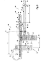
- FIG. 1 shows the basic principle of the invention.
- the device 10 comprises a conveying means 11, which is formed from two separate drums 12 and 13.
- the recordings are attached to movable arms also in a conventional manner and movable, such that the recordings, for example, are connected to suction for holding the article, at least during transport from recording to dispensing parallel to a horizontal plane, in the the articles are promoted.
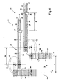
- FIG. 2 shows an embodiment of the device 10, in which the conveying means 11 with two double strands 17, 18, each consisting of two individual strands 19, 20; 21, 22 are formed, is supplied.
- Each double strand 17, 18 is guided on a separate web 23, 24, wherein the webs 23, 24 may be arranged in one plane or on different planes.
- the webs 23, 24 form the longitudinal conveyor 25 and extend parallel to each other and each have a separating means 26, 27 for separating single or multiple tobacco sticks 28 from the strands 19 to 22.
- Each separating means 26, 27 serves to separate two tobacco sticks 28 on a web 23 or 24 simultaneously.
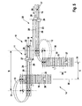
- the embodiment of Figure 3 is similar to the embodiment shown in Figure 2 is formed so that the same reference numerals are used for the same parts.
- the transfer drums 15, 16 are driven in opposite directions, while the drums 12, 13 are driven synchronously.
- the rotation angle of the drums 12, 13 are formed differently, namely for the drum 12, a rotation angle of 90 ° is provided between recording and delivery, while the rotation angle between recording and delivery of the drum 13 is 270 °.
- the two transfer drums 15, 16 are located between the drums 12, 13 so that the distance C between the transfer drums 15, 16 is smaller than the distances A and B, which correspond.
- the distances A, B and C vary in of the embodiment of Figure 3 in size of the distances A, B and C in the embodiment of Figure 2.
- the tobacco sticks 28 are received on different sides (upper side and lower side) of the longitudinal conveyor 25.
- the drum 12 removes the pair of articles from the underside of the web 23, while the drum 13 decreases the article pair from the top of the web 24.
- the counter-rotating drums 12, 13 rotate both at an angle of 90 ° and then give the article pairs to the likewise counter-rotating takeover drums 15, 16, which then convey the article pairs in parallel in the transport direction 34 transaxially.
- the method with the device 10 according to FIG. 5 essentially corresponds to the method with the embodiment described in connection with FIG. However, the drums 12, 13 rotate in opposite directions by a different angle.
- the drum 12 rotates with the tobacco rods 28 by 90 °.
- the drum 13 rotates with the tobacco rods 28 by 270 °.
Landscapes
- Manufacturing Of Cigar And Cigarette Tobacco (AREA)
Description
Die Erfindung betrifft eine Vorrichtung zur Übergabe stabförmiger Artikel, insbesondere Zigaretten, von einem Längsförderer zur längsaxialen Förderung der Artikel auf einen Querförderer zur queraxialen Förderung der Artikel, wobei die Transportrichtungen des Längsförderers und des Querfördereres quer zueinander verlaufen, umfassend ein Fördermittel mit Aufnahmen zur Aufnahme mehrerer Artikel vom Längsförderer und zur Abgabe der aufgenommenen Artikel auf den Querförderer. Des weiteren betrifft die Erfindung ein Verfahren zum Übergeben stabförmiger Artikel, insbesondere Zigaretten, von einem Längsförderer zur längsaxialen Förderung der Artikel auf einen Querförderer zur queraxialen Förderung der Artikel, wobei die Transportrichtungen des Längsförderers und des Querförderer quer zueinander verlaufen, umfassend die Schritte: Aufnehmen mehrerer stabförmiger Artikel vom Längsförderer mittels eines Fördermittels, Drehen des Fördermittels und damit Bewegen der Artikel um einen vorgegebenen Winkel, und Abgeben der Artikel auf den Querförderer.The invention relates to a device for transferring rod-shaped articles, in particular cigarettes, from a longitudinal conveyor for longitudinal axial promotion of the article on a transverse conveyor for Queraxialen promotion of the article, the transport directions of the longitudinal conveyor and the transverse conveyor transverse to each other, comprising a conveyor with receptacles for receiving a plurality Article from the longitudinal conveyor and for the delivery of the recorded articles on the cross conveyor. Furthermore, the invention relates to a method for transferring rod-shaped articles, in particular cigarettes, from a longitudinal conveyor for longitudinal axial promotion of the article on a cross conveyor for Queraxialen promotion of the article, wherein the transport directions of the longitudinal conveyor and the transverse conveyor transverse to each other, comprising the steps of: receiving a plurality rod-shaped article from the longitudinal conveyor by means of a conveyor, rotating the conveyor and thus moving the articles by a predetermined angle, and delivering the articles to the cross conveyor.
Derartige Vorrichtungen und Verfahren kommen insbesondere in der tabakverarbeitenden Industrie zum Einsatz. In einer Zigarettenstrangmaschine werden Stränge aus Tabak hergestellt, die üblicherweise in einzelne oder doppeltlange Tabakstöcke zerteilt werden. Die Tabakstöcke werden in ihrer Längsrichtung gefördert und müssen zur weiteren Bearbeitung, z.B. zum Ansetzten eines Filters, an eine Filteransetzmaschine übergeben werden. Hierzu müssen die Tabakstöcke üblicherweise von ihrer längsaxialen Transportrichtung in eine queraxiale Transportrichtung übertragen werden, wobei die Transportrichtungen auch noch quer zueinander verlaufen.Such devices and methods are used in particular in the tobacco processing industry. In a cigarette rod maker strands are made of tobacco, which are usually cut into single or double-length tobacco stems. The tobacco sticks are conveyed in their longitudinal direction and must be transferred to a Filteransetzmaschine for further processing, eg for attaching a filter. For this purpose, the tobacco sticks usually have to be transferred from their longitudinal axial transport direction in a transverse axial transport direction, wherein the transport directions are also transverse to each other.
Es gibt eine Vielzahl von Vorrichtungen zur Übergabe der stabförmigen Artikel von einem Längsförderer auf einen Querförderer. Bekannte Vorrichtungen weisen ein Fördermittel auf, das mehrere nebeneinander angeordnete Artikel bzw. Tabakstöcke vom Längsförderer aufnimmt und sie auf den Querförderer abgibt. Sämtliche bekannte Vorrichtungen dieser Art sind jedoch ausschließlich dazu geeignet, gleichmäßig nebeneinander angeordnete Tabakstöcke zu übergeben. Die Tabakstöcke werden hierzu von gleichmäßig nebeneinander aus einer Zigarettenstrangmaschine zugeförderten Strängen abgetrennt und zur weiteren Bearbeitung an die Übergabevorrichtung geführt. Als besonders vorteilhaft hat sich allerdings die paarweise Herstellung der Stränge in der Zigarettenstrangmaschine herausgestellt. Bisher ist allerdings nur eine Zigarettenstrangmaschine zur Herstellung eines einzelnen Doppelstranges bekannt, so daß die Vorrichtung zur Übergabe lediglich zur Übergabe eines einzelnen Artikel-Paares ausgebildet waren. Es gibt jedoch Bestrebungen, Zigarettenstrangmaschinen herzustellen, die geeignet sind, mindestens zwei Doppelstränge gleichzeitig zu produzieren.There are a variety of devices for transferring the rod-shaped articles from a longitudinal conveyor to a cross conveyor. Known devices have a conveying means which receives a plurality of juxtaposed articles or tobacco sticks from the longitudinal conveyor and delivers them to the transverse conveyor. However, all known devices of this type are only suitable to pass uniformly juxtaposed tobacco sticks. For this purpose, the tobacco sticks are separated from strands conveyed uniformly next to one another from a cigarette rod machine and fed to the transfer device for further processing. However, the pairwise production of the strands in the cigarette rod machine has proven to be particularly advantageous. So far, however, only a cigarette rod machine for producing a single double strand is known, so that the device for the transfer were designed only for the transfer of a single article pair. However, there are efforts to produce cigarette rod machines capable of producing at least two double strands simultaneously.
Es ist daher Aufgabe der Erfindung, eine einfach aufgebaute und kompakte Vorrichtung zur Übergabe stabförmiger Artikel mit gesteigerter Leistungsfähigkeit zu schaffen. Des weiteren ist es Aufgabe der Erfindung, ein Verfahren vorzuschlagen, das eine einfache und kostengünstige und dennoch gegenüber bekannten Verfahren leistungsfähigere Übergabe gewährleistet.It is therefore an object of the invention to provide a simply constructed and compact device for transferring rod-shaped articles with increased performance. Furthermore, it is an object of the invention to propose a method which ensures a simple and cost-effective, yet over conventional methods more efficient transfer.
Diese Aufgabe wird zum einen durch eine Vorrichtung mit den eingangs genannten Merkmalen dadurch gelöst, daß das Fördermittel zur Aufnahme von mindestens zwei aus jeweils zwei Artikeln gebildeten Artikel-Paaren, von denen jedes Artikel-Paar auf einer separaten Bahn des Längsförderers zugeführt wird, und zur Abgabe der Artikel-Paare an zwei separate Bahnen des Querförderers ausgebildet ist, wobei das Fördermittel zwei separate Trommel umfaßt, die zur Aufnahme jeweils eines Artikel-Paares von einer der Bahnen des Längsförderers und zur Abgabe jeweils eines Artikel-Paares auf eine der Bahnen des Querförderers ausgebildet sind und die Trommeln wahlweise gegenläufig oder gleichlaufend antreibbar sind. Mit dieser erfindungsgemäßen Ausbildung ist eine Leistungsverdopplung gewährleistet, so daß insbesondere auch eine Kombination mit einer Zigarettenstrangmaschine zur Herstellung von zwei mal zwei Strängen, die jeweils als Doppelstrang gefördert werden, möglich ist. Durch die erfindungsgemäße Merkmalskombination ist eine besonders kostengünstige und flexible Möglichkeit geschaffen, mehr als ein Artikel-Paar zu übergeben. Zum einen kann nämlich auf Standard-Teile zurückgegriffen werden, was die Herstellungskosten solcher Vorrichtungen senkt. Zum anderen ist eine unabhängige Aufnahme der Artikel von jeder Bahn des Längsförderers und Abgabe der Artikel auf den Querförderer möglich, wodurch z.B. unterschiedliche Tabaksorten an einer Vorrichtung verarbeitet werden können. Die Wahlmöglichkeit der Antreibbarkeit der Trommeln in gegenläufiger oder gleichlaufender Richtung erhöht zusätzlich die Flexibilität der Vorrichtung sowie die Möglichkeit einer besonders kompakten Anordnung.This object is achieved on the one hand by a device having the features mentioned in that the conveying means for receiving at least two article pairs formed from two articles, of which each pair of articles is fed on a separate web of the longitudinal conveyor, and the Dispensing of the article pairs is formed on two separate tracks of the cross conveyor, wherein the conveying means comprises two separate drum, which for receiving a respective pair of articles from one of the tracks of the longitudinal conveyor and for delivering a respective pair of articles on one of the tracks of the cross conveyor are formed and the drums are alternatively driven in opposite directions or concurrently. With this embodiment of the invention a doubling of performance is ensured, so that in particular a combination with a cigarette rod machine for Production of two times two strands, which are each promoted as a double strand, is possible. The combination of features according to the invention provides a particularly cost-effective and flexible option for transferring more than one pair of articles. On the one hand can be resorted to namely standard parts, which reduces the cost of such devices. On the other hand, an independent recording of the articles of each web of the longitudinal conveyor and delivery of the articles on the cross conveyor is possible, which, for example, different types of tobacco can be processed on a device. The choice of the driveability of the drums in opposite or concurrent direction additionally increases the flexibility of the device and the possibility of a particularly compact arrangement.
In einer bevorzugten Weiterbildung sind die beiden Trommeln in Transportrichtung des Längsförderers hintereinander angeordnet, so daß auf besonders einfache Weise eine Abgabe an zwei parallele Bahnen des Querförderers möglich ist.In a preferred embodiment, the two drums in the transport direction of the longitudinal conveyor are arranged one behind the other, so that in a particularly simple manner a delivery to two parallel tracks of the cross conveyor is possible.
In einer weiteren bevorzugten Ausführungsform ist dem Längsförderer im Bereich beider Bahnen, die parallel zueinander verlaufen und jeweils zur Förderung eines Doppelstranges dienen, jeweils ein Trennmittel zum paarweisen Trennen der Artikel von den Doppelsträngen zugeordnet. Dies erleichtert das paarweise Abnehmen der Artikel vom Längsförderer.In a further preferred embodiment, the longitudinal conveyor in the region of both tracks, which run parallel to each other and each serve to convey a double strand, each associated with a release agent for pairwise separation of the articles of the double strands. This facilitates the pairwise removal of the articles from the longitudinal conveyor.
Eine weitere Ausführungsform ist durch einen Querförderer gekennzeichnet, der zwei separate, die Bahnen bildende Übernahmetrommeln umfaßt, wobei jede Übernahmetrommel mit einer der Trommeln in Wirkverbindung steht. Mit dieser Anordnung ist eine flexible und kompakte Übergabe gewährleistet.Another embodiment is characterized by a cross conveyor comprising two separate transfer drums forming the webs, each transfer drum being operatively connected to one of the drums. With this arrangement, a flexible and compact transfer is guaranteed.
In einer besonders bevorzugten Ausführungsform ist eine der Trommeln des Fördermittels unterhalb der Bahn und die andere Trommel oberhalb der Bahn angeordnet und der Abstand A zwischen den beiden Trennmitteln in Transportrichtung des Längsförderers ist gleich dem Abstand B zwischen den beiden Mittelachsen der Trommeln in Transportrichtung des Längsförderers und gleich dem Abstand C zwischen den beiden Übernahmetrommeln quer zur Transportrichtung des Querförderers. Damit läßt sich eine besonders platzsparende Anordnung schaffen.In a particularly preferred embodiment, one of the drums of the conveyor below the web and the other drum is arranged above the web and the distance A between the two separating means in the transport direction of the longitudinal conveyor is equal to the distance B between the two center axes of the drums in the transport direction of the longitudinal conveyor and equal to the distance C between the two transfer drums transversely to the transport direction of the cross conveyor. This can create a particularly space-saving arrangement.
Zum anderen wird die Aufgabe durch ein Verfahren mit den eingangs genannten Schritten dadurch gelöst, daß mindestens zwei aus jeweils zwei Artikeln bestehende Artikel-Paare, von denen jedes Artikel-Paar auf einer separaten Bahn des Längsförderers zugeführt wird, aufgenommen werden, und die Artikel-Paare an zwei separate Bahnen des Querförderers abgegeben werden, wobei jedes der beiden Artikel-Paare mit einer separaten Trommel des Fördermittels aufgenommen und an eine separate Übernahmetrommel des Querförderers abgegeben wird. Durch diese Kombination der Verfahrensschritte wird ein einfaches und kostengünstiges Verfahren vorgeschlagen, das eine hohe Leistungsfähigkeit aufweist.On the other hand, the object is achieved by a method with the steps mentioned at the outset, in that at least two pairs of articles consisting of two articles, of which each pair of articles is fed on a separate web of the longitudinal conveyor, are received, and the articles Pairs are delivered to two separate webs of the cross conveyor, each of the two pairs of articles is picked up with a separate drum of the conveyor and delivered to a separate transfer drum of the cross conveyor. By this combination of the method steps, a simple and inexpensive method is proposed, which has a high performance.
Weitere vorteilhafte Merkmale und Ausführungsformen ergeben sich aus den Unteransprüchen und der Beschreibung. Besonders bevorzugte Ausführungsformen sowie das Verfahren werden anhand der beigefügten Zeichnung näher erläutert. In der Zeichnung zeigt:
- Fig. 1
- eine schematische Seitenansicht der Vorrichtung in Transportrichtung der längsaxial geführten Artikel mit in der Höhe und seitlich versetzten Trommeln,
- Fig. 2
- eine schematische Darstellung einer ersten Ausführungsform der Vorrichtung,
- Fig. 3
- eine schematische Darstellung einer weiteren Ausführungsform der Vorrichtung,
- Fig. 4
- eine schematische Darstellung einer weiteren Ausführungsform der Vorrichtung, und
- Fig. 5
- eine schematische Darstellung einer weiteren Ausführungsform der Vorrichtung.
- Fig. 1
- a schematic side view of the device in the transport direction of the longitudinal axial guided article with height and laterally offset drums,
- Fig. 2
- a schematic representation of a first embodiment of the device,
- Fig. 3
- a schematic representation of another embodiment of the device,
- Fig. 4
- a schematic representation of another embodiment of the device, and
- Fig. 5
- a schematic representation of another embodiment of the device.
Die gezeigten Vorrichtungen sowie das Verfahren dienen zur Übergabe von zwei mal zwei Artikeln, insbesondere zwei mal zwei doppeltlangen Tabakstöcken von einer Zigarettenstrangmaschine an eine Filteransetzmaschine.The devices shown and the method serve to transfer two times two articles, in particular two times two double-length tobacco sticks from a cigarette rod machine to a filter attachment machine.
Aus der Figur 1 geht das Grundprinzip der Erfindung hervor. Die Vorrichtung 10 umfaßt ein Fördermittel 11, das aus zwei separaten Trommeln 12 und 13 gebildet ist. Die Trommeln 12, 13, die auch als Spinnen, die jeweils nach dem Prinzip der
Aus der Figur 2 geht eine Ausführungsform der Vorrichtung 10 hervor, bei der das Fördermittel 11 mit zwei Doppelsträngen 17, 18, die jeweils aus zwei einzelnen Strängen 19, 20; 21, 22 gebildet sind, beliefert wird. Jeder Doppelstrang 17, 18 ist auf einer separaten Bahn 23, 24 geführt, wobei die Bahnen 23, 24 in einer Ebene oder auf unterschiedlichen Ebenen angeordnet sein können. Die Bahnen 23, 24 bilden den Längsförderer 25 und verlaufen parallel zueinander und verfügen jeweils über ein Trennmittel 26, 27 zum Trennen von einfachen oder mehrfachlangen Tabakstöcken 28 von den Strängen 19 bis 22. Jedes Trennmittel 26, 27 dient zum Trennen von zwei Tabakstöcken 28 auf einer Bahn 23 bzw. 24 gleichzeitig. In Transportrichtung 29 der Bahnen 23, 24 hinter den Trennmitteln 26, 27 ist jeder Bahn 23, 24 eine der Trommeln 12, 13 zugeordnet, wobei beide Trommeln 12, 13 oberhalb der Bahnen 23, 24 angeordnet sind.FIG. 2 shows an embodiment of the
Die Bahn 23 ist in Transportrichtung 29 versetzt zur Bahn 24 angeordnet, derart, daß die Trommeln 12, 13 in Transportrichtung 29 ebenfalls hintereinander angeordnet sind, wobei der Abstand A zwischen den Trennmitteln 26, 27 dem Abstand B zwischen den Mittelachsen 30 und 31 der Trommeln 12, 13 entspricht. Die Trommeln 12, 13 sind gleichlaufend angetrieben. Quer zu den Bahnen 23, 24 des Längsförderers 25 sind die Übernahmetrommeln 15, 16 des Querförderers 14 zum queraxialen Abtransport der Tabakstöcke 28 angeordnet. Der Transportwinkel bzw. der Drehwinkel der Trommeln 12, 13 zwischen der Aufnahme der Tabakstöcke 28 vom Längsförderer 25 und der Abgabe der Tabakstöcke 28 auf den Querförderer 14 beträgt bei beiden Trommeln 12, 13 90°. Die Übernahmetrommeln 15, 16 sind nebeneinander angeordnet, derart, daß die Mittelachsen 32, 33 der Übernahmetrommeln 15, 16 parallel aber in Transportrichtung 34 der Übernahmetrommeln 15, 16 versetzt zueinander verlaufen. Die Übernahmetrommeln 15, 16 sind in dieser Ausführungsform gleichlaufend ausgebildet. Der Abstand C zwischen den beiden Übernahmetrommeln 15, 16, nämlich der Abstand zwischen den mittleren Bewegungsachsen 35, 36 entspricht den Abständen A und B. Mit dieser Anordnung ist eine besonders kompakte Bauform des Fördermittels 11 selbst gewährleistet. Die Übernahmetrommeln 15, 16 sind in Transportrichtung 29 der Bahnen 23, 24 jeweils hinter den korrespondierenden und in Wirkverbindung stehenden Trommeln 12, 13 angeordnet.The
Die Ausführungsform gemäß Figur 3 ist ähnlich der in Figur 2 gezeigten Ausführungsform ausgebildet, so daß für gleiche Teile dieselben Bezugsziffern verwendet werden. Allerdings sind die Übernahmetrommeln 15, 16 gegenläufig angetrieben, während die Trommeln 12, 13 gleichlaufend angetrieben sind. Die Drehwinkel der Trommeln 12, 13 sind unterschiedlich ausgebildet, nämlich für die Trommel 12 ist ein Drehwinkel von 90° zwischen Aufnahme und Abgabe vorgesehen, während der Drehwinkel zwischen Aufnahme und Abgabe der Trommel 13 270° beträgt. Die beiden Übernahmetrommeln 15, 16 liegen zwischen den Trommeln 12, 13 so daß der Abstand C zwischen den Übernahmetrommeln 15, 16 kleiner ist als die Abstände A und B, die sich entsprechen. Durch diese Anordnung ist eine besonders kompakte Bauform der dem Fördermittel 11 nachfolgenden Vorrichtung, z.B. der Filteransetzmaschine, gewährleistet. Allerdings variieren die Abstände A, B und C in der Ausführungsform der Figur 3 der Größe nach von den Abständen A, B und C in der Ausführungsform gemäß Figur 2.The embodiment of Figure 3 is similar to the embodiment shown in Figure 2 is formed so that the same reference numerals are used for the same parts. However, the transfer drums 15, 16 are driven in opposite directions, while the
Eine weitere Ausführungsform ist der Figur 4 zu entnehmen. Es werden wiederum für gleiche Teile dieselben Bezugsziffern verwendet. Die in dieser Figur beschriebene Vorrichtung 10 unterscheidet sich von der zuvor beschriebenen Vorrichtung 10 darin, daß sowohl die Trommeln 12, 13 als auch die Übernahmetrommeln 15, 16 gegenläufig angetrieben sind. Des weiteren ist die Trommel 12 unterhalb der Bahn 23 angeordnet, während die Trommel 13 oberhalb der Bahn 24 angeordnet ist. Der Drehwinkel beträgt für beide Trommeln 12, 13 von der Aufnahme bis zur Abgabe der Tabakstöcke 28 90°. Die Übernahmetrommeln 15, 16 sind wie in der Ausführungsform gemäß Figur 2 wiederum in Transportrichtung 29 jeweils hinter den Trommeln 12, 13 angeordnet, so daß sich hinsichtlich der Abstände A, B und C der Zustand ergibt, der bereits zur Figur 2 erläutert wurde. Auch die Größe der Abstände A, B, C entspricht denen der Figur 2.A further embodiment is shown in FIG. 4. Again, the same reference numbers will be used for the same parts. The
Bei der Ausführungsform gemäß Figur 5 ist wiederum die Trommel 12 unterhalb der Bahn 23 und die Trommel 13 oberhalb der Bahn 24 angeordnet. Allerdings sind die Übernahmetrommeln 15, 16 des Querförderers 14 beide zwischen den Trommeln 12, 13 angeordnet, so daß sich der Zustand hinsichtlich der Abstände (A=B, A, B >C) gemäß Figur 3 wiederholt, was auch für die Größe der Abstände gilt. In dieser Ausführungsform sind jedoch die Trommeln 12, 13 gegenläufig angetrieben, während die Übernahmetrommeln 15, 16 gleichlaufend angetrieben sind. Der Drehwinkel der Trommel 12 beträgt 90°. Der Drehwinkel der Trommel 13 beträgt 270°.In the embodiment according to FIG. 5, in turn, the
Im folgenden wird das Verfahren anhand der einzelnen Ausführungsformen beschrieben:
- Beim Verfahren
mit der Vorrichtung 10 gemäß Figur 2 werden zwei Doppelstränge17, 18 aus Tabak oder dergleichenmit dem Längsförderer 25 längsaxial andas Fördermittel 11 geführt.Jeder Doppelstrang Bahn Von den Doppelsträngen Tabakstöcke 28von den Strängen Bahnen Transportrichtung 29 versetzt zueinander sind, erfolgt auch das Trennen derTabakstöcke 28 orts- und damit zeitversetzt.Der Doppelstrang 17 auf derBahn 23 wird örtlich und zeitlich vordem Doppelstrang 18 auf derBahn 24 getrennt.Die Tabakstöcke 28 werden dann paarweise jeweils einer Trommel 12, 13 zugeführt.Die rotierenden Trommeln Trommeln Tabakstöcke 28von der Trommel 12 örtlich und zeitlich vor dem Abnahmepunkt für dieTabakstöcke 28von der Trommel 13 liegt, erfolgt das Aufnehmen beider Artikel-Paare gleichzeitig.Beide Trommeln vier Tabakstöcke 28 dann zeitgleich an die jeweils korrespondierende Übemahmetrommel 15 bzw. 16 ab.Die Übernahmetrommeln den Bahnen drehen die Übernahmetrommeln die gleiche Transportrichtung 34 auf den beidenBahnen
- In the method with the
device 10 according to FIG. 2, twodouble strands longitudinal conveyor 25 longitudinally to the conveyingmeans 11. Eachdouble strand separate web - Of the
double strands tobacco rods 28 are separated from thestrands tracks transport direction 29 to each other, also takes place the separation of - Tobacco sticks 28 local and thus delayed. The
double strand 17 on theweb 23 becomes spatially and temporally separated from thedouble strand 18 on thetrack 24. The tobacco sticks 28 are then fed in pairs to arespective drum webs drums drum 12 is located locally and temporally before the acceptance point for the tobacco sticks 28 of thedrum 13, the recording takes place both Article pairs at the same time. Both drums 12, 13 rotate with the recorded pairs of articles, namely the total of four tobacco sticks 28, by 90 ° and then give the four tobacco sticks 28 at the same time to the respectively correspondingÜbemahme drum tracks transport 34 on the twotracks
Das Verfahren mit der Vorrichtung gemäß Figur 3 läuft prinzipiell ähnlich ab. Allerdings drehen die Trommeln 12, 13 aufgrund der unterschiedlichen Anordnung der Übernahmetrommeln 15, 16 in unterschiedlichen Winkeln. Die Trommel 12 dreht nach Aufnahme der Tabakstöcke 28 um 90° und gibt die Tabakstöcke 28 dann an die Übemahmetrommel 15 weiter. Die Trommel 13 dreht sich mit den Tabakstöcken 28 um 270° bevor sie die Tabakstöcke 28 an die Übernahmetrommel 16 weitergibt. Die Übernahmetrommeln 15, 16 drehen sich jedoch zum Transport in Transportrichtung 34 gegenläufig.The method with the device according to FIG. 3 runs in principle similarly. However, due to the different arrangement of transfer drums 15, 16, the
Mit der Vorrichtung 10 gemäß Figur 4 werden die Tabakstöcke 28 auf unterschiedlichen Seiten (Oberseite und Unterseite) des Längsförderers 25 aufgenommen. Die Trommel 12 nimmt das Artikel-Paar von der Unterseite der Bahn 23 ab, während die Trommel 13 das Artikel-Paar von der Oberseite der Bahn 24 abnimmt. Die gegenläufig rotierenden Trommeln 12, 13 drehen beide um einen Winkel von 90° und geben die Artikel-Paare dann an die ebenfalls gegenläufig rotierenden Übernahmetrommeln 15, 16 ab, die die Artikel-Paare dann parallel in Transportrichtung 34 queraxial fördern.With the
Das Verfahren mit der Vorrichtung 10 gemäß Figur 5 entspricht im wesentlichen dem Verfahren mit der in Verbindung mit Figur 4 beschriebenen Ausführungsform. Allerdings drehen die Trommeln 12, 13 gegenläufig um einen unterschiedlichen Winkel. Die Trommel 12 dreht mit den Tabakstöcken 28 um 90°. Die Trommel 13 dreht mit den Tabakstöcken 28 um 270°. Nach der zeitgleichen Abgabe der beiden Artikel-Paare auf die gleichlaufend angetriebenen Übernahmetrommeln 15, 16 werden die Arikel-Paare in queraxialer Richtung parallel zueinander in Transportrichtung 34 gefördert.The method with the
Andere Konstellationen sind durch Variation der Position der Trennmittel 26, 27, Variation der Position der Trommeln 12, 13, Variation der Übernahmetrommeln 15, 16 sowie Anordnung der Bahnen 23, 24 zueinander ebenfalls möglich. Entscheidend ist, daß das Fördermittel 11 zwei Aufnahmepunkte für mindestens zwei Artikel-Paare sowie zwei Abgabepunkte für dieselben aufweist.Other constellations are also possible by variation of the position of the separating means 26, 27, variation of the position of the
Claims (12)
- Apparatus for the transfer of rod-shaped articles, in particular cigarettes, from a longitudinal conveyor (25) for longitudinal axial conveying of the articles onto a transverse conveyor (14) for transverse axial conveying of the articles, wherein the directions of transport (arrow 29 or arrow 34) of the longitudinal conveyor (25) and transverse conveyor (14) run transversely to each other, including a conveying means (11) with receptacles for receiving several articles from the longitudinal conveyor (25) and for discharging the received articles onto the transverse conveyor (14), characterized in that the conveying means (11) is designed for receiving at least two pairs of articles each composed of two articles, of which each pair of articles is delivered on a separate track (23, 24) of the longitudinal conveyor (25), and for discharging the pairs of articles to two separate tracks (37, 38) of the transverse conveyor (14), wherein the conveying means (11) includes two separate drums (12, 13) which are designed for receiving one pair of articles each from one of the tracks (23 or 24) of the longitudinal conveyor (25) and for discharging one pair of articles each onto one of the tracks (37, 38) of the transverse conveyor (14) and the drums (12, 13) can be driven optionally in opposite or the same directions.
- Apparatus according to claim 1, characterized in that the conveying means (11) is designed for the simultaneous reception and simultaneous discharge of several pairs of articles.
- Apparatus according to claim 1 or 2, characterized in that the two drums (12, 13) are arranged one behind the other in the direction of transport (arrow 29) of the longitudinal conveyor (25).
- Apparatus according to any one of claims 1 to 3, characterized in that both drums (12, 13) are arranged above the longitudinal conveyor (25).
- Apparatus according to any one of claims 1 to 4, characterized in that one of the drums (12) is arranged below the track (23) and the other drum (13) is arranged above the track (24) or vice versa.
- Apparatus according to any one of claims 1 to 5, characterized in that the longitudinal conveyor (25) in the region of the two tracks (23, 24) which run parallel to each other and each serve to convey a continuous double rod (17, 18) is assigned in each case a separating means (26, 27) for separating the articles from the double rods (17, 18) in pairs.
- Apparatus according to any one of claims 1 to 6, characterized in that the transverse conveyor (14) includes two separate transfer drums (15, 16) forming the tracks (37, 38), wherein each transfer drum (15, 16) is functionally connected to one of the drums (12 or 13).
- Apparatus according to claim 7, characterized in that the two transfer drums (15, 16) can be driven optionally in opposite or the same directions.
- Apparatus according to claim 7 or 8, characterized in that the distance A between the two separating means (26, 27) in the direction of transport (arrow 29) of the longitudinal conveyor (25) is equal to the distance B between the two centre axes (30, 31) of the drums (12, 13) in the direction of transport (arrow 29) of the longitudinal conveyor (29) and equal to the distance C between the two central axes of movement (35, 36) of the transfer drums (15, 16) transverse to the direction of transport (arrow 34) of the transverse conveyor (14).
- Apparatus according to claim 9, characterized in that the distances A and B are the same and the distance C is smaller than the distances A and B.
- Method for the transfer of rod-shaped articles, in particular cigarettes, from a longitudinal conveyor (25) for longitudinal axial conveying of the articles onto a transverse conveyor (14) for transverse axial conveying of the articles, wherein the directions of transport (arrow 29 or arrow 34) of the longitudinal conveyor (25) and transverse conveyor (14) run transversely to each other, including the steps of:- receiving several rod-shaped articles from the longitudinal conveyor (25) by means of a conveying means (11),- rotating the conveying means (11) and so moving the articles through a predetermined angle, and- discharging the articles onto the transverse conveyor (14),characterized in that- at least two pairs of articles each composed of two articles, of which each pair of articles is delivered on a separate track (23, 24) of the longitudinal conveyor (25), are received, and- the pairs of articles are discharged to two separate tracks (37, 38) of the transverse conveyor (14), wherein- each of the two pairs of articles are received with a separate drum (12, 13) of the conveying means (11) and discharged to a separate transfer drum (15, 16) of the transverse conveyor (14).
- Method according to claim 13, characterized in that several pairs of articles are received simultaneously from several separate tracks (23, 24) and discharged simultaneously onto several separate tracks (37, 38).
Priority Applications (2)
| Application Number | Priority Date | Filing Date | Title |
|---|---|---|---|
| EP04090356A EP1516546B1 (en) | 2003-09-16 | 2004-09-16 | Apparatus and method for transferring rod-like articles |
| PL04090356T PL1516546T3 (en) | 2003-09-16 | 2004-09-16 | Apparatus and method for transferring rod-like articles |
Applications Claiming Priority (3)
| Application Number | Priority Date | Filing Date | Title |
|---|---|---|---|
| EP03090298 | 2003-09-16 | ||
| EP03090298 | 2003-09-16 | ||
| EP04090356A EP1516546B1 (en) | 2003-09-16 | 2004-09-16 | Apparatus and method for transferring rod-like articles |
Publications (2)
| Publication Number | Publication Date |
|---|---|
| EP1516546A1 EP1516546A1 (en) | 2005-03-23 |
| EP1516546B1 true EP1516546B1 (en) | 2007-06-27 |
Family
ID=34196148
Family Applications (1)
| Application Number | Title | Priority Date | Filing Date |
|---|---|---|---|
| EP04090356A Expired - Lifetime EP1516546B1 (en) | 2003-09-16 | 2004-09-16 | Apparatus and method for transferring rod-like articles |
Country Status (2)
| Country | Link |
|---|---|
| EP (1) | EP1516546B1 (en) |
| PL (1) | PL1516546T3 (en) |
Cited By (1)
| Publication number | Priority date | Publication date | Assignee | Title |
|---|---|---|---|---|
| RU2842907C2 (en) * | 2021-02-10 | 2025-07-03 | Филип Моррис Продактс С.А. | Method of producing rod-like articles for tobacco industry, device for manufacturing rod-like articles and system for manufacturing rod-like articles |
Families Citing this family (3)
| Publication number | Priority date | Publication date | Assignee | Title |
|---|---|---|---|---|
| DE102011110552B4 (en) | 2011-08-12 | 2013-10-10 | Hauni Maschinenbau Ag | Conveying device and method for conveying rod-shaped articles of the tobacco-processing industry |
| DE102020117743A1 (en) * | 2020-07-06 | 2022-01-13 | Hauni Maschinenbau Gmbh | Transfer device and method for transferring rod-shaped articles from a rope-forming device to a drum device |
| PL436921A1 (en) * | 2021-02-10 | 2022-08-16 | International Tobacco Machinery Poland Spółka Z Ograniczoną Odpowiedzialnością | Method of producing rod-like articles of the tobacco industry, device for production of rod-like articles and system for production of rod-like articles |
Citations (5)
| Publication number | Priority date | Publication date | Assignee | Title |
|---|---|---|---|---|
| GB2099780A (en) * | 1981-06-05 | 1982-12-15 | Gd Spa | Transferring cigarette pieces during cigarette manufacture |
| US4645063A (en) * | 1981-11-24 | 1987-02-24 | G.D Societa Per Azioni | Cigarette transfer device |
| US4804079A (en) * | 1986-10-30 | 1989-02-14 | Korber Ag | Apparatus for transporting groups of rod-shaped articles of the tobacco processing industry |
| US4827948A (en) * | 1986-12-01 | 1989-05-09 | Korber Ag | Apparatus for changing the direction of transport of rod-shaped articles of the tobacco processing industry |
| US5255777A (en) * | 1991-09-06 | 1993-10-26 | Korber Ag | Apparatus for transporting groups of rod-shaped articles of the tobacco processing industry |
Family Cites Families (3)
| Publication number | Priority date | Publication date | Assignee | Title |
|---|---|---|---|---|
| US4406197A (en) * | 1980-08-16 | 1983-09-27 | Hauni-Werke Korber & Co. Kg | Method and apparatus for transporting rod-shaped articles |
| IT1245763B (en) * | 1991-02-11 | 1994-10-14 | Gd Spa | DEVICE FOR THE TRANSFER OF CIGARETTES OF CIGARETTE FROM A DOUBLE WHEEL PACKAGING MACHINE TO A FILTER FEEDING MACHINE. |
| IT1286275B1 (en) * | 1996-10-24 | 1998-07-08 | Gd Spa | DEVICE FOR TRANSFERRING CIGARETTE STUDS FROM A DOUBLE CIGARETTE STICK PACKAGING MACHINE TO A MACHINE |
-
2004
- 2004-09-16 PL PL04090356T patent/PL1516546T3/en unknown
- 2004-09-16 EP EP04090356A patent/EP1516546B1/en not_active Expired - Lifetime
Patent Citations (5)
| Publication number | Priority date | Publication date | Assignee | Title |
|---|---|---|---|---|
| GB2099780A (en) * | 1981-06-05 | 1982-12-15 | Gd Spa | Transferring cigarette pieces during cigarette manufacture |
| US4645063A (en) * | 1981-11-24 | 1987-02-24 | G.D Societa Per Azioni | Cigarette transfer device |
| US4804079A (en) * | 1986-10-30 | 1989-02-14 | Korber Ag | Apparatus for transporting groups of rod-shaped articles of the tobacco processing industry |
| US4827948A (en) * | 1986-12-01 | 1989-05-09 | Korber Ag | Apparatus for changing the direction of transport of rod-shaped articles of the tobacco processing industry |
| US5255777A (en) * | 1991-09-06 | 1993-10-26 | Korber Ag | Apparatus for transporting groups of rod-shaped articles of the tobacco processing industry |
Cited By (1)
| Publication number | Priority date | Publication date | Assignee | Title |
|---|---|---|---|---|
| RU2842907C2 (en) * | 2021-02-10 | 2025-07-03 | Филип Моррис Продактс С.А. | Method of producing rod-like articles for tobacco industry, device for manufacturing rod-like articles and system for manufacturing rod-like articles |
Also Published As
| Publication number | Publication date |
|---|---|
| PL1516546T3 (en) | 2007-11-30 |
| EP1516546A1 (en) | 2005-03-23 |
Similar Documents
| Publication | Publication Date | Title |
|---|---|---|
| EP3259999B1 (en) | Transport of rod-shaped articles from the tobacco processing industry | |
| DE2809160A1 (en) | Combination cigarette filter transfer device - with distance lug on leading end of holder for accurate cavity recess | |
| DE4129672A1 (en) | CONVEYOR DEVICE FOR CONVEYING ROD-SHAPED ITEMS OF THE TOBACCO-PROCESSING INDUSTRY | |
| DE3735006C2 (en) | Conveying device for conveying rod-shaped articles of the tobacco processing industry | |
| DE1009087B (en) | Plug conveyor device | |
| DE10156303A1 (en) | Method and device for producing filter cigarettes | |
| EP2659792A2 (en) | Method and apparatus for arranging filter segment groups | |
| EP1374706B1 (en) | Filter feeding for a filter assembly machine | |
| EP1638419B1 (en) | Double-belt filter assembly machine, and production of filter cigarettes | |
| DE2162295C3 (en) | Method and apparatus for making tip cigarettes | |
| EP1516547B1 (en) | Apparatus and method for transferring rod-like articles | |
| DE69414639T2 (en) | Method and device for producing filter cigarettes | |
| EP3641572B1 (en) | Manufacture of smoking products | |
| EP1516545B1 (en) | Machine and method for simultaneously producing a number of cigarette rods | |
| EP1510142B1 (en) | Manipulation of rodlike articles from the tobacco manufacturing industry | |
| DE102016114641A1 (en) | Conveyor drum of the tobacco processing industry | |
| DE4103017C2 (en) | Method and device for producing filter cigarettes | |
| DE102019134097A1 (en) | Conveyor drum of the tobacco processing industry | |
| EP1516546B1 (en) | Apparatus and method for transferring rod-like articles | |
| EP1779739B1 (en) | Apparatus for feeding filters | |
| EP2696707B1 (en) | Conveying rod-shaped articles of the tobacco processing industry | |
| DE69218352T2 (en) | Process for the production of filter cigarettes of various lengths | |
| DE3934660C2 (en) | ||
| EP3262959B1 (en) | Positioning of rod-shaped articles of the tobacco processing industry into an insertion device | |
| DE4039134C2 (en) | Manufacturing process for filter cigarettes |
Legal Events
| Date | Code | Title | Description |
|---|---|---|---|
| PUAI | Public reference made under article 153(3) epc to a published international application that has entered the european phase |
Free format text: ORIGINAL CODE: 0009012 |
|
| AK | Designated contracting states |
Kind code of ref document: A1 Designated state(s): AT BE BG CH CY CZ DE DK EE ES FI FR GB GR HU IE IT LI LU MC NL PL PT RO SE SI SK TR |
|
| AX | Request for extension of the european patent |
Extension state: AL HR LT LV MK |
|
| 17P | Request for examination filed |
Effective date: 20050922 |
|
| AKX | Designation fees paid |
Designated state(s): AT BE BG CH CY CZ DE DK EE ES FI FR GB GR HU IE IT LI LU MC NL PL PT RO SE SI SK TR |
|
| TPAC | Observations filed by third parties |
Free format text: ORIGINAL CODE: EPIDOSNTIPA |
|
| GRAP | Despatch of communication of intention to grant a patent |
Free format text: ORIGINAL CODE: EPIDOSNIGR1 |
|
| GRAS | Grant fee paid |
Free format text: ORIGINAL CODE: EPIDOSNIGR3 |
|
| GRAA | (expected) grant |
Free format text: ORIGINAL CODE: 0009210 |
|
| AK | Designated contracting states |
Kind code of ref document: B1 Designated state(s): AT BE BG CH CY CZ DE DK EE ES FI FR GB GR HU IE IT LI LU MC NL PL PT RO SE SI SK TR |
|
| REG | Reference to a national code |
Ref country code: GB Ref legal event code: FG4D Free format text: NOT ENGLISH |
|
| REG | Reference to a national code |
Ref country code: CH Ref legal event code: EP |
|
| REG | Reference to a national code |
Ref country code: IE Ref legal event code: FG4D Free format text: LANGUAGE OF EP DOCUMENT: GERMAN |
|
| REF | Corresponds to: |
Ref document number: 502004004178 Country of ref document: DE Date of ref document: 20070809 Kind code of ref document: P |
|
| PG25 | Lapsed in a contracting state [announced via postgrant information from national office to epo] |
Ref country code: SE Free format text: LAPSE BECAUSE OF FAILURE TO SUBMIT A TRANSLATION OF THE DESCRIPTION OR TO PAY THE FEE WITHIN THE PRESCRIBED TIME-LIMIT Effective date: 20070927 |
|
| GBT | Gb: translation of ep patent filed (gb section 77(6)(a)/1977) |
Effective date: 20071004 |
|
| REG | Reference to a national code |
Ref country code: PL Ref legal event code: T3 |
|
| REG | Reference to a national code |
Ref country code: IE Ref legal event code: FD4D |
|
| PG25 | Lapsed in a contracting state [announced via postgrant information from national office to epo] |
Ref country code: ES Free format text: LAPSE BECAUSE OF FAILURE TO SUBMIT A TRANSLATION OF THE DESCRIPTION OR TO PAY THE FEE WITHIN THE PRESCRIBED TIME-LIMIT Effective date: 20071008 Ref country code: PT Free format text: LAPSE BECAUSE OF FAILURE TO SUBMIT A TRANSLATION OF THE DESCRIPTION OR TO PAY THE FEE WITHIN THE PRESCRIBED TIME-LIMIT Effective date: 20071127 Ref country code: CZ Free format text: LAPSE BECAUSE OF FAILURE TO SUBMIT A TRANSLATION OF THE DESCRIPTION OR TO PAY THE FEE WITHIN THE PRESCRIBED TIME-LIMIT Effective date: 20070627 Ref country code: IE Free format text: LAPSE BECAUSE OF FAILURE TO SUBMIT A TRANSLATION OF THE DESCRIPTION OR TO PAY THE FEE WITHIN THE PRESCRIBED TIME-LIMIT Effective date: 20070627 Ref country code: SI Free format text: LAPSE BECAUSE OF FAILURE TO SUBMIT A TRANSLATION OF THE DESCRIPTION OR TO PAY THE FEE WITHIN THE PRESCRIBED TIME-LIMIT Effective date: 20070627 Ref country code: BG Free format text: LAPSE BECAUSE OF FAILURE TO SUBMIT A TRANSLATION OF THE DESCRIPTION OR TO PAY THE FEE WITHIN THE PRESCRIBED TIME-LIMIT Effective date: 20070927 |
|
| EN | Fr: translation not filed | ||
| PG25 | Lapsed in a contracting state [announced via postgrant information from national office to epo] |
Ref country code: SK Free format text: LAPSE BECAUSE OF FAILURE TO SUBMIT A TRANSLATION OF THE DESCRIPTION OR TO PAY THE FEE WITHIN THE PRESCRIBED TIME-LIMIT Effective date: 20070627 |
|
| BERE | Be: lapsed |
Owner name: HAUNI MASCHINENBAU A.G. Effective date: 20070930 |
|
| PG25 | Lapsed in a contracting state [announced via postgrant information from national office to epo] |
Ref country code: DK Free format text: LAPSE BECAUSE OF FAILURE TO SUBMIT A TRANSLATION OF THE DESCRIPTION OR TO PAY THE FEE WITHIN THE PRESCRIBED TIME-LIMIT Effective date: 20070627 Ref country code: GR Free format text: LAPSE BECAUSE OF FAILURE TO SUBMIT A TRANSLATION OF THE DESCRIPTION OR TO PAY THE FEE WITHIN THE PRESCRIBED TIME-LIMIT Effective date: 20070928 Ref country code: MC Free format text: LAPSE BECAUSE OF NON-PAYMENT OF DUE FEES Effective date: 20070930 |
|
| PLBE | No opposition filed within time limit |
Free format text: ORIGINAL CODE: 0009261 |
|
| STAA | Information on the status of an ep patent application or granted ep patent |
Free format text: STATUS: NO OPPOSITION FILED WITHIN TIME LIMIT |
|
| PG25 | Lapsed in a contracting state [announced via postgrant information from national office to epo] |
Ref country code: RO Free format text: LAPSE BECAUSE OF FAILURE TO SUBMIT A TRANSLATION OF THE DESCRIPTION OR TO PAY THE FEE WITHIN THE PRESCRIBED TIME-LIMIT Effective date: 20070627 |
|
| 26N | No opposition filed |
Effective date: 20080328 |
|
| PG25 | Lapsed in a contracting state [announced via postgrant information from national office to epo] |
Ref country code: FR Free format text: LAPSE BECAUSE OF FAILURE TO SUBMIT A TRANSLATION OF THE DESCRIPTION OR TO PAY THE FEE WITHIN THE PRESCRIBED TIME-LIMIT Effective date: 20080222 |
|
| PG25 | Lapsed in a contracting state [announced via postgrant information from national office to epo] |
Ref country code: BE Free format text: LAPSE BECAUSE OF NON-PAYMENT OF DUE FEES Effective date: 20070930 |
|
| PG25 | Lapsed in a contracting state [announced via postgrant information from national office to epo] |
Ref country code: AT Free format text: LAPSE BECAUSE OF NON-PAYMENT OF DUE FEES Effective date: 20070916 |
|
| PG25 | Lapsed in a contracting state [announced via postgrant information from national office to epo] |
Ref country code: EE Free format text: LAPSE BECAUSE OF FAILURE TO SUBMIT A TRANSLATION OF THE DESCRIPTION OR TO PAY THE FEE WITHIN THE PRESCRIBED TIME-LIMIT Effective date: 20070627 |
|
| PG25 | Lapsed in a contracting state [announced via postgrant information from national office to epo] |
Ref country code: FI Free format text: LAPSE BECAUSE OF FAILURE TO SUBMIT A TRANSLATION OF THE DESCRIPTION OR TO PAY THE FEE WITHIN THE PRESCRIBED TIME-LIMIT Effective date: 20070627 |
|
| PG25 | Lapsed in a contracting state [announced via postgrant information from national office to epo] |
Ref country code: CY Free format text: LAPSE BECAUSE OF FAILURE TO SUBMIT A TRANSLATION OF THE DESCRIPTION OR TO PAY THE FEE WITHIN THE PRESCRIBED TIME-LIMIT Effective date: 20070627 |
|
| PG25 | Lapsed in a contracting state [announced via postgrant information from national office to epo] |
Ref country code: LU Free format text: LAPSE BECAUSE OF NON-PAYMENT OF DUE FEES Effective date: 20070916 |
|
| PG25 | Lapsed in a contracting state [announced via postgrant information from national office to epo] |
Ref country code: HU Free format text: LAPSE BECAUSE OF FAILURE TO SUBMIT A TRANSLATION OF THE DESCRIPTION OR TO PAY THE FEE WITHIN THE PRESCRIBED TIME-LIMIT Effective date: 20071228 Ref country code: TR Free format text: LAPSE BECAUSE OF FAILURE TO SUBMIT A TRANSLATION OF THE DESCRIPTION OR TO PAY THE FEE WITHIN THE PRESCRIBED TIME-LIMIT Effective date: 20070627 |
|
| PGFP | Annual fee paid to national office [announced via postgrant information from national office to epo] |
Ref country code: CH Payment date: 20110922 Year of fee payment: 8 |
|
| PGFP | Annual fee paid to national office [announced via postgrant information from national office to epo] |
Ref country code: GB Payment date: 20110920 Year of fee payment: 8 Ref country code: PL Payment date: 20110817 Year of fee payment: 8 |
|
| PGFP | Annual fee paid to national office [announced via postgrant information from national office to epo] |
Ref country code: NL Payment date: 20110927 Year of fee payment: 8 |
|
| REG | Reference to a national code |
Ref country code: NL Ref legal event code: V1 Effective date: 20130401 |
|
| REG | Reference to a national code |
Ref country code: CH Ref legal event code: PL |
|
| GBPC | Gb: european patent ceased through non-payment of renewal fee |
Effective date: 20120916 |
|
| PG25 | Lapsed in a contracting state [announced via postgrant information from national office to epo] |
Ref country code: CH Free format text: LAPSE BECAUSE OF NON-PAYMENT OF DUE FEES Effective date: 20120930 Ref country code: LI Free format text: LAPSE BECAUSE OF NON-PAYMENT OF DUE FEES Effective date: 20120930 Ref country code: GB Free format text: LAPSE BECAUSE OF NON-PAYMENT OF DUE FEES Effective date: 20120916 |
|
| PG25 | Lapsed in a contracting state [announced via postgrant information from national office to epo] |
Ref country code: NL Free format text: LAPSE BECAUSE OF NON-PAYMENT OF DUE FEES Effective date: 20130401 |
|
| PG25 | Lapsed in a contracting state [announced via postgrant information from national office to epo] |
Ref country code: PL Free format text: LAPSE BECAUSE OF NON-PAYMENT OF DUE FEES Effective date: 20120916 |
|
| PGFP | Annual fee paid to national office [announced via postgrant information from national office to epo] |
Ref country code: IT Payment date: 20130920 Year of fee payment: 10 |
|
| REG | Reference to a national code |
Ref country code: PL Ref legal event code: LAPE |
|
| PGFP | Annual fee paid to national office [announced via postgrant information from national office to epo] |
Ref country code: DE Payment date: 20130930 Year of fee payment: 10 |
|
| REG | Reference to a national code |
Ref country code: DE Ref legal event code: R119 Ref document number: 502004004178 Country of ref document: DE |
|
| REG | Reference to a national code |
Ref country code: DE Ref legal event code: R119 Ref document number: 502004004178 Country of ref document: DE Effective date: 20150401 |
|
| PG25 | Lapsed in a contracting state [announced via postgrant information from national office to epo] |
Ref country code: DE Free format text: LAPSE BECAUSE OF NON-PAYMENT OF DUE FEES Effective date: 20150401 |
|
| PG25 | Lapsed in a contracting state [announced via postgrant information from national office to epo] |
Ref country code: IT Free format text: LAPSE BECAUSE OF NON-PAYMENT OF DUE FEES Effective date: 20140916 |