EP1223326A2 - Verfahren zur Steuerung einer eingespritzten Kraftstoffmenge während eines Startvorganges und zur Erkennung einer Kraftstoffqualität - Google Patents
Verfahren zur Steuerung einer eingespritzten Kraftstoffmenge während eines Startvorganges und zur Erkennung einer Kraftstoffqualität Download PDFInfo
- Publication number
- EP1223326A2 EP1223326A2 EP01250446A EP01250446A EP1223326A2 EP 1223326 A2 EP1223326 A2 EP 1223326A2 EP 01250446 A EP01250446 A EP 01250446A EP 01250446 A EP01250446 A EP 01250446A EP 1223326 A2 EP1223326 A2 EP 1223326A2
- Authority
- EP
- European Patent Office
- Prior art keywords
- starting
- engine
- increase factor
- quantity increase
- time
- Prior art date
- Legal status (The legal status is an assumption and is not a legal conclusion. Google has not performed a legal analysis and makes no representation as to the accuracy of the status listed.)
- Granted
Links
Images



Classifications
-
- F—MECHANICAL ENGINEERING; LIGHTING; HEATING; WEAPONS; BLASTING
- F02—COMBUSTION ENGINES; HOT-GAS OR COMBUSTION-PRODUCT ENGINE PLANTS
- F02D—CONTROLLING COMBUSTION ENGINES
- F02D41/00—Electrical control of supply of combustible mixture or its constituents
- F02D41/0025—Controlling engines characterised by use of non-liquid fuels, pluralities of fuels, or non-fuel substances added to the combustible mixtures
-
- F—MECHANICAL ENGINEERING; LIGHTING; HEATING; WEAPONS; BLASTING
- F02—COMBUSTION ENGINES; HOT-GAS OR COMBUSTION-PRODUCT ENGINE PLANTS
- F02D—CONTROLLING COMBUSTION ENGINES
- F02D19/00—Controlling engines characterised by their use of non-liquid fuels, pluralities of fuels, or non-fuel substances added to the combustible mixtures
- F02D19/06—Controlling engines characterised by their use of non-liquid fuels, pluralities of fuels, or non-fuel substances added to the combustible mixtures peculiar to engines working with pluralities of fuels, e.g. alternatively with light and heavy fuel oil, other than engines indifferent to the fuel consumed
- F02D19/0602—Control of components of the fuel supply system
- F02D19/0607—Control of components of the fuel supply system to adjust the fuel mass or volume flow
- F02D19/061—Control of components of the fuel supply system to adjust the fuel mass or volume flow by controlling fuel injectors
-
- F—MECHANICAL ENGINEERING; LIGHTING; HEATING; WEAPONS; BLASTING
- F02—COMBUSTION ENGINES; HOT-GAS OR COMBUSTION-PRODUCT ENGINE PLANTS
- F02D—CONTROLLING COMBUSTION ENGINES
- F02D19/00—Controlling engines characterised by their use of non-liquid fuels, pluralities of fuels, or non-fuel substances added to the combustible mixtures
- F02D19/06—Controlling engines characterised by their use of non-liquid fuels, pluralities of fuels, or non-fuel substances added to the combustible mixtures peculiar to engines working with pluralities of fuels, e.g. alternatively with light and heavy fuel oil, other than engines indifferent to the fuel consumed
- F02D19/0626—Measuring or estimating parameters related to the fuel supply system
- F02D19/0634—Determining a density, viscosity, composition or concentration
- F02D19/0636—Determining a density, viscosity, composition or concentration by estimation, i.e. without using direct measurements of a corresponding sensor
-
- F—MECHANICAL ENGINEERING; LIGHTING; HEATING; WEAPONS; BLASTING
- F02—COMBUSTION ENGINES; HOT-GAS OR COMBUSTION-PRODUCT ENGINE PLANTS
- F02D—CONTROLLING COMBUSTION ENGINES
- F02D41/00—Electrical control of supply of combustible mixture or its constituents
- F02D41/02—Circuit arrangements for generating control signals
- F02D41/04—Introducing corrections for particular operating conditions
- F02D41/06—Introducing corrections for particular operating conditions for engine starting or warming up
- F02D41/062—Introducing corrections for particular operating conditions for engine starting or warming up for starting
-
- F—MECHANICAL ENGINEERING; LIGHTING; HEATING; WEAPONS; BLASTING
- F02—COMBUSTION ENGINES; HOT-GAS OR COMBUSTION-PRODUCT ENGINE PLANTS
- F02D—CONTROLLING COMBUSTION ENGINES
- F02D41/00—Electrical control of supply of combustible mixture or its constituents
- F02D41/02—Circuit arrangements for generating control signals
- F02D41/14—Introducing closed-loop corrections
- F02D41/1497—With detection of the mechanical response of the engine
-
- F—MECHANICAL ENGINEERING; LIGHTING; HEATING; WEAPONS; BLASTING
- F02—COMBUSTION ENGINES; HOT-GAS OR COMBUSTION-PRODUCT ENGINE PLANTS
- F02D—CONTROLLING COMBUSTION ENGINES
- F02D19/00—Controlling engines characterised by their use of non-liquid fuels, pluralities of fuels, or non-fuel substances added to the combustible mixtures
- F02D19/06—Controlling engines characterised by their use of non-liquid fuels, pluralities of fuels, or non-fuel substances added to the combustible mixtures peculiar to engines working with pluralities of fuels, e.g. alternatively with light and heavy fuel oil, other than engines indifferent to the fuel consumed
- F02D19/0639—Controlling engines characterised by their use of non-liquid fuels, pluralities of fuels, or non-fuel substances added to the combustible mixtures peculiar to engines working with pluralities of fuels, e.g. alternatively with light and heavy fuel oil, other than engines indifferent to the fuel consumed characterised by the type of fuels
- F02D19/0649—Liquid fuels having different boiling temperatures, volatilities, densities, viscosities, cetane or octane numbers
-
- F—MECHANICAL ENGINEERING; LIGHTING; HEATING; WEAPONS; BLASTING
- F02—COMBUSTION ENGINES; HOT-GAS OR COMBUSTION-PRODUCT ENGINE PLANTS
- F02D—CONTROLLING COMBUSTION ENGINES
- F02D2200/00—Input parameters for engine control
- F02D2200/02—Input parameters for engine control the parameters being related to the engine
- F02D2200/06—Fuel or fuel supply system parameters
- F02D2200/0611—Fuel type, fuel composition or fuel quality
- F02D2200/0612—Fuel type, fuel composition or fuel quality determined by estimation
-
- F—MECHANICAL ENGINEERING; LIGHTING; HEATING; WEAPONS; BLASTING
- F02—COMBUSTION ENGINES; HOT-GAS OR COMBUSTION-PRODUCT ENGINE PLANTS
- F02D—CONTROLLING COMBUSTION ENGINES
- F02D2200/00—Input parameters for engine control
- F02D2200/02—Input parameters for engine control the parameters being related to the engine
- F02D2200/06—Fuel or fuel supply system parameters
- F02D2200/0614—Actual fuel mass or fuel injection amount
-
- F—MECHANICAL ENGINEERING; LIGHTING; HEATING; WEAPONS; BLASTING
- F02—COMBUSTION ENGINES; HOT-GAS OR COMBUSTION-PRODUCT ENGINE PLANTS
- F02N—STARTING OF COMBUSTION ENGINES; STARTING AIDS FOR SUCH ENGINES, NOT OTHERWISE PROVIDED FOR
- F02N11/00—Starting of engines by means of electric motors
- F02N11/08—Circuits specially adapted for starting of engines
- F02N11/0848—Circuits specially adapted for starting of engines with means for detecting successful engine start, e.g. to stop starter actuation
-
- Y—GENERAL TAGGING OF NEW TECHNOLOGICAL DEVELOPMENTS; GENERAL TAGGING OF CROSS-SECTIONAL TECHNOLOGIES SPANNING OVER SEVERAL SECTIONS OF THE IPC; TECHNICAL SUBJECTS COVERED BY FORMER USPC CROSS-REFERENCE ART COLLECTIONS [XRACs] AND DIGESTS
- Y02—TECHNOLOGIES OR APPLICATIONS FOR MITIGATION OR ADAPTATION AGAINST CLIMATE CHANGE
- Y02T—CLIMATE CHANGE MITIGATION TECHNOLOGIES RELATED TO TRANSPORTATION
- Y02T10/00—Road transport of goods or passengers
- Y02T10/10—Internal combustion engine [ICE] based vehicles
- Y02T10/30—Use of alternative fuels, e.g. biofuels
Definitions
- the invention relates to methods for controlling an amount of fuel supplied during a starting process of an internal combustion engine with the in the preamble of Claims 1 and 12 mentioned features and uses of the method according to Claims 26, 30 and 31.
- a cold start or a start process at low engine temperatures requires, among other things special control measures in the area of fuel supply.
- the starting process can be divided into individual phases. First, the Internal combustion engine accelerated to a minimum speed by a starter. After reaching the minimum speed, a fuel quantity is provided, which is in the Compared to fuel quantities under higher operating temperatures by a starting quantity increase factor is significantly raised. This increase is usually with or short after the internal combustion engine has run up to a target idling speed withdrawn.
- a basic problem in the startup process with both spark ignited, in particular direct injection, internal combustion engines (gasoline engines) as well self-igniting engines (diesel engines) is a wetting of the cold combustion chamber walls, the valves, the piston crown and the intake manifold with a fuel film.
- This one also as Known disadvantage of wall film problems can be seen, for example, in one Direct injection, in the tendency of the injected fuel to adhere to the To deposit the piston crown on which the injection jet is usually directed.
- substantial portions of the inducted or injected The amount of fuel when the engine was first ignited, or not at all burned because they cannot evaporate because the engine is still cold.
- it has a significant influence on provided drive torque, fuel consumption, total emissions and a general operating behavior of spark-ignited or auto-igniting Internal combustion engines of motor vehicles.
- vapor pressure and octane or cetane number operating parameters such as injection and Ignition times, injection pressure, exhaust gas recirculation mass flow, boost pressure, Operating state of a tank ventilation and position of a camshaft actuator, with regard Fuel consumption, emissions and operating behavior, especially when not warm engine, can be optimized.
- the object of the present invention is therefore to provide a method for adapting a amount of fuel supplied during a starting process To provide internal combustion engine through which a better adaptation of the Starting quantity increase factor to the actual conditions during the Starting process, in particular to an existing fuel quality, can take place. In order to the overall emissions and fuel consumption of the motor vehicle should go hand in hand be reduced. Furthermore, a method is to be created with which reliable Statements can be made about the fuel quality. These statements are meant to be made available to an engine control as early as possible.
- these measures reduce the number during the starting process Amounts of fuel supplied. As a result, wall film formation of the fuel is reduced and total unburned hydrocarbon HC and carbon monoxide emissions CO of the motor vehicle is reduced.
- the starting quantity increase factor is preferred by specifying a maximum Limit the starting quantity increase factor.
- the maximum starting quantity increase factor can in particular depending on parameters such as the engine temperature, the number engine revolutions and the elapsed time since the start of the engine amount of fuel already supplied and / or the engine speed. By the limitation of the starting quantity increase factor prevents oversteering.
- a third point in time predetermined or by reaching a threshold value for the number of revolutions determined since the start of the start process.
- the starting quantity increase factor is lowered when the engine speed is below the second at the third point in time Threshold for the engine speed and / or the threshold for the Engine speed change is. In this way, oversized wall film formation is said to contribute bad fuels can be avoided.
- the Reaching a fourth point in time the starting process is canceled when the engine speed below the second threshold or the threshold for the Engine speed change is.
- the fourth point in time can be predefined. Is conceivable also, the fourth point in time based on a threshold value for the number of revolutions to determine since the start of the start process. Starter operation is preferred at the same time or with a time delay when the engine is aborted to start the engine prevented.
- a subsequent and if necessary in further repetition starts immediately with the maximum starting quantity increase factor the fuel supply started. It is preferred for the repeat starts a fifth point in time or by reaching a threshold for the number determined at revolutions since the start of the starting process.
- the starting quantity increase factor is starting from the maximum starting quantity increase factor lowered when the engine speed at the fifth time below the second Threshold value and / or the threshold value for the engine speed change.
- An ongoing repeat start can be canceled and by one or more subsequent repeat starts are replaced.
- a successful start can be achieved by an idling speed or based on a speed change in a predetermined Time interval can be determined.
- the initial starting quantity increase factor for a short time interval in particular at most 1 s, preferably at ⁇ 0.5 s, and is particularly preferably set to ⁇ 0.2 s, kept approximately constant.
- the initial starting amount increase factor decreased.
- very poor ignition and / or Evaporation behavior of the fuel has been determined by the engine start only after When the time interval has been determined, it can also be used to shorten the start time the starting start amount increase factor can be increased.
- the starting quantity increase factor is increased progressively, if in one a comparatively good fuel quality was determined in the preceding determination, the fuel has a good ignition and / or vaporization behavior. If worse Fuel quality, on the other hand, is largely linear or with the increase characteristic little progression. In this way, a start time should be kept as short as possible without having to make significant cuts in determining fuel quality must be taken.
- the starting quantity after reaching the Start-up detection approximately recognized start time for a predetermined time interval to keep constant.
- a course of engine speed is recorded during this time interval. Since the course is often characteristic of the fuel quality, it becomes the same Determination to improve the informative value also taken into account.
- the time interval itself can depend on one or more engine or company specific Parameters can be determined. In particular, a combustion process, a Number of cylinders, one cubic capacity, one bore / stroke ratio, one friction power, one Starter speed, an outside temperature or an oil pressure.
- one or more engine or company specific parameters when recognizing the Fuel quality taken into account In this way, the accuracy of the determination be further increased.
- engine- or company-specific parameters in question the outside temperature, the starter speed, an electrical system voltage, the Combustion process, the number of cylinders, the displacement, the bore / stroke ratio, the Friction power, the fuel pressure in front of an injector, a crank angle-related Start of injection, a throttle valve angle, the position of a camshaft actuator Exhaust gas recirculation mass flow, the position of a tank ventilation valve, one Coolant temperature, a fuel temperature, a fresh air mass flow, the position of a boost pressure actuator, the state of a suspension and damping of an engine mount, the Type of an identification converter (transmission) connected downstream of the internal combustion engine, a rotational inertia and a natural frequency and damping of the entrained Drive train.
- the startup is preferably detected by specifying another one Engine speed threshold that is greater than the first threshold and / or by specifying a threshold value for a change in speed over time.
- the Threshold values are measured in such a way that they are successful when they are reached Startup is accepted.
- the second method according to the invention can preferably be used to influence the Engine operating parameters of the motor vehicle used in the subsequent normal operation especially after starting the engine during the warm-up phase.
- the one in question upcoming engine operating parameters include in particular an injection and Ignition timing, an injection pressure, the exhaust gas recirculation mass flow, a boost pressure, the operation of a tank ventilation, the position of the camshaft actuator and / or the Position of a cargo movement door.
- Both methods according to the invention are preferably used when the Internal combustion engine is spark-ignited (gasoline engine), in particular a direct-injection gasoline engine.
- spark-ignited gasoline engine
- direct-injection gasoline engine in particular a direct-injection gasoline engine.
- the use of the methods is also preferred in self-igniting internal combustion engines (diesel engines).
- FIG. 1 shows the course over time of a starting quantity increase factor F, one Engine speed n and a lambda value ⁇ upstream of a pre-catalytic converter (i.e. in Raw exhaust gas) during a starting process of an internal combustion engine conventional procedure.
- the courses shown are of course only can be seen schematically and can be designed in a specific form for a particular Take internal combustion engine slightly modified courses.
- the necessary resources for influencing a quantity of fuel supplied to the internal combustion engine are known in particular for carrying out the increase in the fuel quantity.
- controllable injection systems are for self-igniting or spark-ignited Motors known with which the fuel supply can be controlled at least quantitatively.
- a Coordination of individual units involved in the starting process can be done in a known manner an engine control unit.
- the internal combustion engine is initially subjected to a torque by means of a starter until a first threshold value S n1 for the speed n is reached (time t 1 ).
- a first threshold value S n1 for the speed n is reached at time t 1 .
- the fuel supply is released by injection or intake.
- the quantity of fuel supplied is increased during the starting process by a starting quantity increase factor F kon and kept constant for a predeterminable interval, for example until the engine speed n has reached a desired idling speed n empty (time t 2 ).
- the conventional starting quantity increase factor F kon is gradually reduced to the value 1, thus ending the increase in the fuel supply compared to "normal operation".
- the conventional starting quantity increase factor F kon is dimensioned in such a way that a successful engine start can be expected even with very poor fuel quality, in particular extremely poorly evaporable and / or flammable fuels.
- This also means that strong wall film formation has to be accepted.
- area 10 The larger the area 10, the higher the HC emission. It is particularly disadvantageous here that, at this early point in time, downstream catalyst systems have not yet been heated to their operating temperature and HC conversion is not carried out or only to a very limited extent.
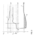
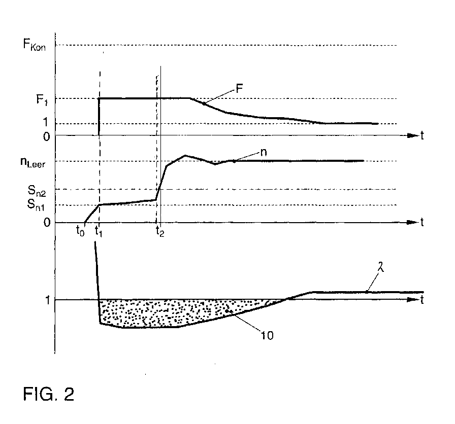
- FIG. 2 shows the courses of the starting quantity increase factor F, the engine speed n and the lambda value ⁇ upstream of the pre-catalytic converter according to the inventive procedure according to a first embodiment when using commercially available fuel.
- a second time t 2 is specified at the same time, which is determined either by a fixed time interval after the start of the start process (time t 0 ) or by reaching a threshold value for a number of revolutions since the start of the start process.
- the fuel quality is so good that a successful engine start was recognized before the second time t 2 was reached.
- the successful start can be recognized in a manner known per se by means of a run-up detection, for example by reaching the desired idling speed n empty or, as here, using a speed change in a predetermined time interval, i.e. using the slope of curve n. If the speed change exceeds a predefinable threshold value for the engine speed change, a successful start is assumed. After the engine has started, the starting quantity increase factor F is initially held for a short time and then gradually returned to the value 1. It becomes clear that, compared to conventional start-up control, significantly lower amounts of fuel are injected and consequently the emission of unconverted hydrocarbons is also reduced (area 10).
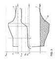
- FIG. 3 shows a starting process according to the method according to the invention analogous to FIG. 2, but with a lower quality fuel.
- the starting quantity increase factor F is increased when the engine speed n at time t 2 is below a second threshold value S n2 and / or a change in engine speed since the start of the increase (time t 1 ) is below a threshold value.
- the starting quantity increase factor F is increased here with largely linear dynamics.
- the dynamics of the increase in the starting quantity increase factor F can be specified as a function of an elapsed time since the start of the starting process, the engine speed n and / or the change in engine speed, so that courses other than linear are also conceivable.
- the starting quantity increase factor F gradually returned to 1. Also - according to the representation - the starting quantity increase factor available at the start time F are still held for a predefinable time interval.
- the total emission of hydrocarbons when starting with the existing fuel quality is still significantly lower than in the prior art.
- the peak emissions postponed in time Subordinate catalyst systems can then already have reached their minimum operating temperature for converting the pollutants, so that an overall emission of the motor vehicle drops.
- FIG. 4 shows an alternative increase in the starting quantity increase factor F in otherwise the same boundary conditions as in the starting process according to FIG. 3. Instead of one linear increase there is a gradual increase in the starting quantity increase factor F until the engine start-up detection detects a successful start.
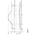
- FIG. 5 shows a starting process with an extremely poor and non-standard fuel on the course of the engine speed n and the starting quantity increase factor F.
- the starting quantity factor F is increased if the second threshold value S n2 and / or the threshold value for the engine speed change is not exceeded at the time t 2 .
- the increase is initially linear, but is limited overall by specifying a maximum starting quantity increase factor F max .
- the maximum starting quantity increase factor F max is intended to prevent excessive wall film formation and can be determined as a function of an engine temperature, a number of engine revolutions since the start of the start process, a time interval since the start of the start process, an amount of fuel already supplied and / or the engine speed n.
- a third point in time t 3 is specified or determined by reaching a threshold value for the number of revolutions since the start of the starting process.
- the starting quantity increase factor F is reduced if the engine speed n at time t 3 is still below the second threshold value S n2 and / or the threshold value for the engine speed change in order to prevent excessive film film wetting.
- the lowering takes place, for example, linearly up to a level that can deviate from the initial start quantity increase factor F 1 , preferably exceeding the initial start quantity increase factor F 1 .
- a fourth time t 4 is predetermined or determined by reaching a threshold value for the number of revolutions since the start of the starting process.
- the starting process is terminated when the engine speed n is below the second threshold value S n2 or the threshold value for the engine speed change at the time t 4 .
- starter operation is prevented by the engine control unit, so that a new attempt to start is only possible with a time delay due to the starter being re-engaged.
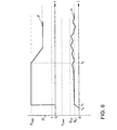
- At least one subsequent repeat start can be initiated in accordance with the procedure shown in FIG. 6.
- the maximum start quantity increase factor F max is started immediately after reaching the first threshold value S n1 (time t 1 ) in order to protect a battery in the motor vehicle.
- a fifth point in time t 5 is specified or determined by reaching a threshold value for the number of revolutions since the start of the starting process. If the engine speed n at time t 5 is still below the second threshold value S n2 and / or the threshold value for the engine speed change, the starting quantity increase factor F is reduced.
- an ongoing repeat start can also be canceled and repeated by one or more subsequent repeat starts.
- FIG. 7 shows the courses of the starting quantity increase factor F and the engine speed n after the procedure of the second method according to the invention with a fuel of low quality.
- This method also serves to determine a current fuel quality, for example in order to adapt subsequent starting processes to it.
- the engine is first accelerated by the starter until the speed threshold S n1 is reached (time t 1 ).
- the fuel supply is released (time t 2 ).
- the increase takes place in such a way that a low initial start quantity increase factor F 1 is initially specified.
- the initial starting quantity increase factor F 1 is selected such that a successful start is not yet to be expected, or at most can only be expected for fuels with a high vapor pressure or good ignitability. To achieve this, the initial starting quantity increase factor F 1 may be reduced if a good to very good fuel quality was determined in a previous determination. If, on the other hand, a very poor fuel quality has been determined in previous determinations, it may make sense to increase the starting quantity increase factor F 1 in order to shorten the starting process.
- a time interval dt v with a constant starting quantity increase factor F 1 is set to ⁇ 1 s, in particular ⁇ 0.5 s, preferably to ⁇ 0.2 s, depending on the fuel quality in the previous measurements. If a successful start is detected in the time interval dt v , the initial starting quantity increase factor F 1 is reduced in subsequent starting processes.
- a phase begins at time t 3 , in which the starting quantity increase factor F is increased steadily.
- the increase is largely linear. With very good fuel qualities, the increase can also be done progressively in order to shorten the starting process.
- a start time t S can be determined by means of a run-up detection.
- a further threshold value S nS for the engine speed n and / or a threshold value for a change in speed in a specific measurement interval is specified for start-up detection, upon reaching which a successful start is assumed.
- a time interval dt S from the beginning of the increase (time t 3 ) to the starting time t S is recorded at the same time.
- This time interval dt S and / or the starting time t S of the present starting quantity increase factor S F serves as an output for determining the fuel quality.
- a statement about the fuel quality, in particular an ignitability and / or vaporizability of the fuel can be made directly with the aid of characteristic curves or characteristic maps.
- the starting quantity increase factor F is reduced to a value of 1 with a predefinable characteristic, that is to say the increase in the quantity of fuel supplied is withdrawn.
- FIG. 8 shows a variation of the course of the starting quantity increase factor F and the engine speed n during the starting process according to the second method according to the invention.
- An increase in the starting quantity increase factor F in the time interval dt s takes place here progressively, since usually good to very good fuel quality can be expected.
- the starting quantity increase factor F is kept constant for a time interval dt m to the value of the starting quantity increasing factor F S at the starting time t S.
- a curve of the engine speed n is recorded in this time interval dt m .
- the course of the engine speed in the time interval dt m is generally characteristic of the present fuel quality with regard to vapor pressure or ignitability and is therefore taken into account to increase the meaningfulness of the quality determination.
- a duration of the time interval dt m is determined as a function of one or more engine or operation-specific parameters.
- a combustion process, a number of cylinders, a cubic capacity, a bore / stroke ratio, friction power, a starter speed, an outside temperature or an oil pressure can be considered as engine- and operation-specific parameters.
- the starter speed an electrical system voltage
- the combustion process the number of cylinders, the displacement, the ratio Bore / stroke, the friction
- the fuel pressure in front of an injector crank angle-related injection start a throttle valve angle
- the position of a Camshaft actuator the position of a Camshaft actuator
- an exhaust gas recirculation mass flow
Landscapes
- Engineering & Computer Science (AREA)
- Chemical & Material Sciences (AREA)
- Combustion & Propulsion (AREA)
- Mechanical Engineering (AREA)
- General Engineering & Computer Science (AREA)
- Oil, Petroleum & Natural Gas (AREA)
- Electrical Control Of Air Or Fuel Supplied To Internal-Combustion Engine (AREA)
- Combined Controls Of Internal Combustion Engines (AREA)
Abstract
Description
- Figur 1
- einen Verlauf eines Startmengen-Anhebungsfaktors, einer Motordrehzahl und eines Lambdawertes vor einem Vorkatalysator während eines Startvorganges beim Stand der Technik;
- Figur 2
- einen Verlauf des Startmengen-Anhebungsfaktors, der Motordrehzahl und des Lambdawertes vor dem Vorkatalysator während eines Startvorganges nach dem ersten erfindungsgemäßen Verfahren;
- Figur 3
- wie Figur 2, jedoch mit einem schlechten Kraftstoff und linearer Anhebung des Startmengen-Anhebungsfaktors;
- Figur 4
- wie Figur 3, jedoch mit stufenweiser Anhebung des Startmengen-Anhebungsfaktors;
- Figur 5
- einen Verlauf des Startmengen-Anhebungsfaktors und der Motordrehzahl mit einem extrem schlechten Kraftstoff;
- Figur 6
- einen Verlauf des Startmengen-Anhebungsfaktors und der Motordrehzahl bei einem Wiederholstart mit einem extrem schlechten Kraftstoff;
- Figur 7
- einen Verlauf des Startmengen-Anhebungsfaktors und der Motordrehzahl während eines Startvorganges nach dem zweiten erfindungsgemäßen Verfahren in einer ersten Variante; und
- Figur 8
- einen Verlauf des Startmengen-Anhebungsfaktors und der Motordrehzahl während eines Startvorganges nach dem zweiten erfindungsgemäßen Verfahren in einer weiteren Variante.
- 10
- Fläche zur Abschätzung einer HC-Emission während des Startvorganges
- dtm
- Zeitintervall bei konstantem Startmengen-Anhebungsfaktor Fs
- dts
- Zeitintervall seit Beginn der Anhebung bis zum Startzeitpunkt ts
- dtv
- Zeitintervall bei konstantem Anfangsstartmengen-Anhebungsfaktor F1
- F
- Startmengen-Anhebungsfaktor
- F1
- Anfangsstartmengen-Anhebungsfaktor
- Fkon
- konventioneller Startmengen-Anhebungsfaktor
- Fmax
- maximaler Startmengen-Anhebungsfaktor
- Fs
- Startmengen-Anhebungsfaktor zum Startzeitpunkt ts
- n
- Drehzahl
- nleer
- Leerlaufdrehzahl
- Sn1
- erster Schwellenwert für die Motordrehzahl n
- Sn2
- zweiter Schwellenwert für die Motordrehzahl n
- Sns
- weiterer Schwellenwert für die Motordrehzahl n
- t0
- Beginn des Startvorganges
- ti
- Zeitpunkte
- ts
- Motorstartzeitpunkt
Claims (31)
- Verfahren zur Steuerung einer zugeführten Kraftstoffmenge während eines Startvorganges einer Verbrennungskraftmaschine, bei dem die zugeführte Kraftstoffmenge um einen Startmengen-Anhebungsfaktor (F) erhöht wird, dadurch gekennzeichnet, dass(a) nach Erreichen eines ersten Schwellenwertes (Sn1) für eine Motordrehzahl (n) zu einem ersten Zeitpunkt (t1) der Startmengen-Anhebungsfaktor (F) zunächst auf einen Anfangsstartmengen-Anhebungsfaktor (F1) gesetzt wird,(b) ein zweiter Zeitpunkt (t2) vorgegeben oder durch Erreichen eines Schwellenwertes für eine Anzahl an Umdrehungen seit Beginn des Startvorganges bestimmt wird,(c) der Startmengen-Anhebungsfaktor (F) angehoben wird, wenn die Motordrehzahl (n) zum zweiten Zeitpunkt (t2) unterhalb eines zweiten Schwellenwertes (Sn2) und/oder eine Motordrehzahländerung seit Beginn der Anhebung zum ersten Zeitpunkt (t1) unterhalb eines Schwellenwertes liegt, und(d) der Startmengen-Anhebungsfaktor (F) nach erfolgreichem Motorstart zurückgenommen wird.
- Verfahren nach Anspruch 1, dadurch gekennzeichnet, dass eine Dynamik der Anhebung des Startmengen-Anhebungsfaktors (F) in Abhängigkeit von einer verstrichenen Zeit seit Beginn des Startvorganges, der Anzahl der Motorumdrehungen seit Beginn des Startvorganges, der Motordrehzahl (n) und/oder der Motordrehzahländerung vorgegeben wird.
- Verfahren nach den Ansprüchen 1 oder 2, dadurch gekennzeichnet, dass der Startmengen-Anhebungsfaktor (F) durch Vorgabe eines maximalen Startmengen-Anhebungsfaktors (Fmax) begrenzt wird.
- Verfahren nach Anspruch 3, dadurch gekennzeichnet, dass der maximale Startmengen-Anhebungsfaktor (Fmax) in Abhängigkeit von einer Motortemperatur, einer Anzahl an Motorumdrehungen seit Beginn des Startvorganges, einem Zeitintervall seit Beginn des Startvorganges, einer bereits zugeführten Kraftstoffmenge und/oder der Motordrehzahl (n) bestimmt wird.
- Verfahren nach einem der Ansprüche 1 bis 4, dadurch gekennzeichnet, dass(a) ein dritter Zeitpunkt (t3) vorgegeben oder durch Erreichen eines Schwellenwertes für die Anzahl an Umdrehungen seit Beginn des Startvorganges bestimmt wird und(b) der Startmengen-Anhebungsfaktor (F) abgesenkt wird, wenn die Motordrehzahl (n) zum dritten Zeitpunkt (t3) unterhalb des zweiten Schwellenwertes (Sn2) und/oder des Schwellenwertes für die Motordrehzahländerung liegt.
- Verfahren nach Anspruch 5, dadurch gekennzeichnet, dass(a) ein vierter Zeitpunkt (t4) vorgegeben oder durch Erreichen eines Schwellenwertes für die Anzahl an Umdrehungen seit Beginn des Startvorganges bestimmt wird und(b) der Startvorgang abgebrochen wird, wenn die Motordrehzahl (n) zum vierten Zeitpunkt (t4) unterhalb des zweiten Schwellenwertes (Sn2) oder des Schwellenwertes für die Motordrehzahländerung liegt.
- Verfahren nach Anspruch 6, dadurch gekennzeichnet, dass zeitgleich oder zeitversetzt mit Abbruch des Startvorganges ein Anlasserbetrieb unterbunden wird.
- Verfahren nach den Ansprüchen 6 oder 7, dadurch gekennzeichnet, dass nach Abbruch des Startvorganges bei zumindest einem nachfolgenden Wiederholstart sofort mit dem maximalen Startmengen-Anhebungsfaktor (Fmax) begonnen wird.
- Verfahren nach Anspruch 8, dadurch gekennzeichnet, dass(a) bei einem Wiederholstart ein fünfter Zeitpunkt (t5) vorgegeben oder durch Erreichen eines Schwellenwertes für die Anzahl an Umdrehungen seit Beginn des Startvorganges bestimmt wird und(b) der Startmengen-Anhebungsfaktor (F) ausgehend von dem maximalen Startmengen-Anhebungsfaktor (Fmax) abgesenkt wird, wenn die Motordrehzahl (n) zum fünften Zeitpunkt (t5) unterhalb des zweiten Schwellenwertes (Sn2) und/oder des Schwellenwertes für die Motordrehzahländerung liegt.
- Verfahren nach den Ansprüchen 8 oder 9, dadurch gekennzeichnet, dass ein laufender Wiederholstart abgebrochen werden kann und durch einen oder mehrere nachfolgende Wiederholstarts wiederholbar ist.
- Verfahren nach einem der Ansprüche 1 bis 10, dadurch gekennzeichnet, dass ein erfolgreicher Start durch Erreichen einer Leerlaufdrehzahl (nleer) oder anhand einer Drehzahländerung in einem vorgegebenen Zeitintervall bestimmt wird.
- Verfahren zur Steuerung einer zugeführten Kraftstoffmenge während eines Startvorganges einer Verbrennungskraftmaschine, bei dem die zugeführte Kraftstoffmenge um einen Startmengen-Anhebungsfaktor (F) erhöht wird, dadurch gekennzeichnet, dass(a) nach Erreichen eines Schwellenwertes (Sn1) für eine Motordrehzahl (n) der Startmengen-Anhebungsfaktor (F) zunächst auf einen niedrigen Anfangsstartmengen-Anhebungsfaktor (F1) gesetzt wird,(b) nachfolgend der Startmengen-Anhebungsfaktor (F) stetig steigend angehoben wird,(c) ein Startzeitpunkt (ts) für einen Motorhochlauf mittels einer Hochlauferkennung bestimmt wird,(d) ein Startmengen-Anhebungsfaktor (Fs) im Startzeitpunkt (ts) und/oder ein Zeitintervall (dts) von Beginn der stetigen Anhebung bis zum Startzeitpunkt (ts) erfasst wird, und(e) in Abhängigkeit vom Startmengen-Anhebungsfaktor (Fs) und/oder dem Zeitintervall (dts) eine Kraftstoffqualität bestimmt wird.
- Verfahren nach Anspruch 12, dadurch gekennzeichnet, dass der Anfangsstartmengen-Anhebungsfaktor (F1) derart gewählt wird, dass bei seiner Anwendung ein erfolgreicher Start noch nicht oder allenfalls bei Kraftstoffen mit hoher Qualität zu erwarten ist.
- Verfahren nach einem der Ansprüche 12 oder 13, dadurch gekennzeichnet, dass eine Zündwilligkeit und/oder eine Verdampfbarkeit des Kraftstoffs in Abhängigkeit vom Startmengen-Anhebungsfaktor (Fs) und/oder dem Zeitintervall (dts) bestimmt werden.
- Verfahren nach einem der Ansprüche 12 bis 14, dadurch gekennzeichnet, dass der Anfangsstartmengen-Anhebungsfaktor (F1) für ein kurzes Zeitintervall (dtv) annähernd konstant gehalten wird, ehe die Anhebung beginnt.
- Verfahren nach Anspruch 15, dadurch gekennzeichnet, dass das Zeitintervall (dtv) auf höchstens 1 s, insbesondere auf höchstens 0,5 s, insbesondere auf höchstens 0,2 s gesetzt wird.
- Verfahren nach einem der Ansprüche 15 oder 16, dadurch gekennzeichnet, dass der Anfangsstartmengen-Anhebungsfaktor (F1) in nachfolgenden Startvorgängen erniedrigt wird, wenn der Startzeitpunkt (ts) im Zeitintervall (dtv) liegt.
- Verfahren nach einem der Ansprüche 15 oder 16, dadurch gekennzeichnet, dass der Anfangsstartmengen-Anhebungsfaktor (F1) in nachfolgenden Startvorgängen erhöht wird, wenn der Startzeitpunkt (ts) wesentlich nach dem Zeitintervall (dtv) liegt.
- Verfahren nach einem der Ansprüche 12 bis 18, dadurch gekennzeichnet, dass die Anhebung des Startmengen-Anhebungsfaktors (F) progressiv erfolgt, wenn der Kraftstoff in einer vorhergehenden Bestimmung gutes Zünd- und/oder Verdampfverhalten zeigt.
- Verfahren nach einem der Ansprüche 12 bis 18, dadurch gekennzeichnet, dass die Anhebung des Startmengen-Anhebungsfaktor (F) linear oder mit nur geringer Progression erfolgt, wenn der Kraftstoff in einer vorhergehenden Bestimmung schlechtes Zünd- und/oder Verdampfverhalten zeigt.
- Verfahren nach einem der Ansprüche 12 bis 20, dadurch gekennzeichnet, dass zur Hochlauferkennung ein weiterer Schwellenwert (Sns) für die Motordrehzahl (n) und/oder ein Schwellenwert für eine Drehzahländerung in einem Messintervall vorgegeben wird, bei deren Erreichen ein erfolgreicher Motorhochlauf angenommen wird.
- Verfahren nach einem der Ansprüche 12 bis 21, dadurch gekennzeichnet, dass der Startmengen-Anhebungsfaktor (F) nach Erreichen des Startzeitpunktes (ts) für ein vorgebbares Zeitintervall (dtm) annähernd konstant gehalten wird, wobei ein Verlauf der Motordrehzahl (n) in diesem Zeitintervall (dtm) erfasst und bei der Bestimmung der Kraftstoffqualität mit einfließt.
- Verfahren nach Anspruch 22, dadurch gekennzeichnet, dass das Zeitintervall (dtm) in Abhängigkeit von einem oder mehreren motor- oder betriebsspezifischen Parametern, wie einem Brennverfahren, einer Zylinderzahl, einem Hubraum, einem Verhältnis Bohrung/Hub, einer Reibleistung, einer Starterdrehzahl, einer Außentemperatur oder einem Öldruck, ermittelt wird.
- Verfahren nach einem der Ansprüche 12 bis 23, dadurch gekennzeichnet, dass ein oder mehrere motor- oder betriebsspezifische Parameter bei der Erkennung der Kraftstoffqualität berücksichtigt werden.
- Verfahren nach Anspruch 24, dadurch gekennzeichnet, dass die motor- oder betriebsspezifischen Parameter zur Bestimmung der Kraftstoffqualität die Außentemperatur, die Starterdrehzahl, eine Bordnetzspannung, das Brennverfahren, die Zylinderzahl, den Hubraum, das Verhältnis Bohrung/Hub, die Reibleistung, einen Kraftstoffdruck vor einem Injektor, einen kurbelwinkelbezogenen Einspritzbeginn, ein Drosselklappenwinkel, eine Position eines Nockenwellenstellers, ein Abgasrückführ-Massenstrom, eine Stellung eines Tankentlüftungsventils, eine Kühlmitteltemperatur, eine Kraftstofftemperatur, einen Frischluft-Massenstrom, eine Position eines Ladedruckstellers, Zustand einer Federung und Dämpfung eines Motorlagers, Art eines der Verbrennungskraftmaschine nachgeschalteten Kennungswandlers (Getriebe), eine rotatorische Trägheit und Eigenfrequenz und Dämpfung des mitgeschleppten Antriebsstranges umfassen.
- Verwendung eines nach einem der Ansprüche 12 bis 25 zur Erkennung einer Kraftstoffqualität.
- Verwendung nach Anspruch 26, dadurch gekennzeichnet, dass Motorbetriebsparameter des Kraftfahrzeuges in Abhängigkeit von der Kraftstoffqualität beeinflusst werden.
- Verwendung nach einem der Ansprüche 26 oder 27, dadurch gekennzeichnet, dass die Motorbetriebsparameter Einspritz- und Zündzeitpunkt, Einspritzdruck, Abgasrückführ-Massenstrom, Ladedruck, Betrieb einer Tankentlüftung, Position des Nockenwellenstellers und/oder Position einer Ladungsbewegungsklappe umfassen.
- Verwendung nach einem der Ansprüche 26 bis 28 insbesondere zur Beeinflussung der Motorbetriebsparameter nach dem Motorstart während der Warmlaufphase des Motors.
- Verwendung eines Verfahrens nach einem der Ansprüche 1 bis 11 oder nach einem der Ansprüche 12 bis 25 zur Steuerung einer zugeführten Kraftstoffmenge während eines Startvorganges eines Ottomotors, insbesondere eines direkteinspritzenden Ottomotors.
- Verwendung eines Verfahrens nach einem der Ansprüche 1 bis 11 oder nach einem der Ansprüche 12 bis 25 zur Steuerung einer zugeführten Kraftstoffmenge während eines Startvorganges eines Dieselmotors.
Applications Claiming Priority (5)
| Application Number | Priority Date | Filing Date | Title |
|---|---|---|---|
| DE10101006 | 2001-01-11 | ||
| DE1010079 | 2001-01-11 | ||
| DE10101007 | 2001-01-11 | ||
| DE2001101006 DE10101006A1 (de) | 2001-01-11 | 2001-01-11 | Verfahren zur Steuerung einer eingespritzten Kraftstoffmenge während eines Startvorganges einer Verbrennungskraftmaschine |
| DE2001101007 DE10101007A1 (de) | 2001-01-11 | 2001-01-11 | Verfahren zur Erkennung der Kraftstoffqualität |
Publications (3)
| Publication Number | Publication Date |
|---|---|
| EP1223326A2 true EP1223326A2 (de) | 2002-07-17 |
| EP1223326A3 EP1223326A3 (de) | 2004-04-21 |
| EP1223326B1 EP1223326B1 (de) | 2006-03-15 |
Family
ID=29251729
Family Applications (1)
| Application Number | Title | Priority Date | Filing Date |
|---|---|---|---|
| EP01250446A Expired - Lifetime EP1223326B1 (de) | 2001-01-11 | 2001-12-19 | Verfahren zur Steuerung einer eingespritzten Kraftstoffmenge während eines Startvorganges und zur Erkennung einer Kraftstoffqualität |
Country Status (2)
| Country | Link |
|---|---|
| EP (1) | EP1223326B1 (de) |
| DE (1) | DE50109209D1 (de) |
Cited By (10)
| Publication number | Priority date | Publication date | Assignee | Title |
|---|---|---|---|---|
| FR2847000A1 (fr) * | 2002-11-12 | 2004-05-14 | Bosch Gmbh Robert | Procede de correction de l'enrichissement d'un melange carburant/air |
| US7163002B1 (en) * | 2006-03-02 | 2007-01-16 | Ford Global Technologies, Llc | Fuel injection system and method |
| US7363916B2 (en) | 2003-01-13 | 2008-04-29 | Siemens Aktiengesellschaft | Fuel injection system and method for determining the feed pressure of a fuel pump |
| EP1918556A1 (de) * | 2006-10-23 | 2008-05-07 | Delphi Technologies, Inc. | Verfahren und Vorrichtung zur Regelung einer Brennkraftmaschine |
| WO2008131978A1 (de) * | 2007-04-26 | 2008-11-06 | Robert Bosch Gmbh | Verfahren und vorrichtung zur steuerung einer brennkraftmaschine |
| WO2009007607A1 (fr) * | 2007-07-09 | 2009-01-15 | Peugeot Citroën Automobiles SA | Procede de demarrage a froid d'un moteur a combustion interne |
| WO2009007209A3 (de) * | 2007-07-06 | 2009-03-12 | Bosch Gmbh Robert | Verfahren zum betreiben eines hybridfahrzeugs |
| WO2009092496A1 (de) * | 2008-01-24 | 2009-07-30 | Continental Automotive Gmbh | Verfahren und vorrichtung zum betreiben einer brennkraftmaschine |
| EP2481906A1 (de) * | 2011-01-27 | 2012-08-01 | Honda Motor Co., Ltd. | Motorsteuerungsvorrichtung und Cogenerierungsvorrichtung mit der Motorsteuerungsvorrichtung |
| FR2980529A1 (fr) * | 2011-09-26 | 2013-03-29 | Renault Sa | Commande d'injection de carburant au demarrage d'un moteur thermique |
Family Cites Families (4)
| Publication number | Priority date | Publication date | Assignee | Title |
|---|---|---|---|---|
| JPS5746031A (en) * | 1980-09-01 | 1982-03-16 | Toyota Motor Corp | Method of controlling supplied quantity of fuel to internal combustion engine |
| US4582036A (en) * | 1983-09-12 | 1986-04-15 | Honda Giken Kogyo K.K. | Fuel supply control method for internal combustion engines immediately after cranking |
| DE3537996A1 (de) * | 1985-10-25 | 1987-05-07 | Bosch Gmbh Robert | Startsteuerung fuer kraftstoffeinspritzanlagen |
| JP3784080B2 (ja) * | 1994-06-16 | 2006-06-07 | 株式会社デンソー | 暖機過程時の燃料噴射量補正方法 |
-
2001
- 2001-12-19 EP EP01250446A patent/EP1223326B1/de not_active Expired - Lifetime
- 2001-12-19 DE DE50109209T patent/DE50109209D1/de not_active Expired - Lifetime
Cited By (19)
| Publication number | Priority date | Publication date | Assignee | Title |
|---|---|---|---|---|
| FR2847000A1 (fr) * | 2002-11-12 | 2004-05-14 | Bosch Gmbh Robert | Procede de correction de l'enrichissement d'un melange carburant/air |
| US7363916B2 (en) | 2003-01-13 | 2008-04-29 | Siemens Aktiengesellschaft | Fuel injection system and method for determining the feed pressure of a fuel pump |
| US7163002B1 (en) * | 2006-03-02 | 2007-01-16 | Ford Global Technologies, Llc | Fuel injection system and method |
| EP1918556A1 (de) * | 2006-10-23 | 2008-05-07 | Delphi Technologies, Inc. | Verfahren und Vorrichtung zur Regelung einer Brennkraftmaschine |
| US7725240B2 (en) | 2006-10-23 | 2010-05-25 | Delphi Technologies, Inc. | System and method for control of an internal combustion engine |
| WO2008131978A1 (de) * | 2007-04-26 | 2008-11-06 | Robert Bosch Gmbh | Verfahren und vorrichtung zur steuerung einer brennkraftmaschine |
| WO2009007209A3 (de) * | 2007-07-06 | 2009-03-12 | Bosch Gmbh Robert | Verfahren zum betreiben eines hybridfahrzeugs |
| DE102007031551B4 (de) * | 2007-07-06 | 2018-11-15 | Robert Bosch Gmbh | Verfahren zum Betreiben eines Hybridfahrzeugs sowie Computerprogramm für das Verfahren |
| CN101790630B (zh) * | 2007-07-09 | 2013-05-08 | 标致·雪铁龙汽车公司 | 用于冷启动内燃发动机的方法 |
| WO2009007607A1 (fr) * | 2007-07-09 | 2009-01-15 | Peugeot Citroën Automobiles SA | Procede de demarrage a froid d'un moteur a combustion interne |
| FR2918713A1 (fr) * | 2007-07-09 | 2009-01-16 | Peugeot Citroen Automobiles Sa | Procede de demarrage a froid d'un moteur a combustion interne. |
| US8141542B2 (en) | 2007-07-09 | 2012-03-27 | Peugeot Citroen Automobiles Sa | Method for the cold start of an internal combustion engine |
| WO2009092496A1 (de) * | 2008-01-24 | 2009-07-30 | Continental Automotive Gmbh | Verfahren und vorrichtung zum betreiben einer brennkraftmaschine |
| US8494753B2 (en) | 2008-01-24 | 2013-07-23 | Continental Automotive Gmbh | Method and device for operating an internal combustion engine |
| US9429086B2 (en) | 2011-01-27 | 2016-08-30 | Honda Motor Co., Ltd. | Engine control device and cogeneration apparatus employing the engine control device |
| EP2481906A1 (de) * | 2011-01-27 | 2012-08-01 | Honda Motor Co., Ltd. | Motorsteuerungsvorrichtung und Cogenerierungsvorrichtung mit der Motorsteuerungsvorrichtung |
| WO2013045805A1 (fr) * | 2011-09-26 | 2013-04-04 | Renault S.A.S. | Commande d'injection de carburant au démarrage d'un moteur thermique |
| FR2980529A1 (fr) * | 2011-09-26 | 2013-03-29 | Renault Sa | Commande d'injection de carburant au demarrage d'un moteur thermique |
| CN103782014A (zh) * | 2011-09-26 | 2014-05-07 | 雷诺股份公司 | 控制内燃机起动时的燃料喷射 |
Also Published As
| Publication number | Publication date |
|---|---|
| EP1223326B1 (de) | 2006-03-15 |
| DE50109209D1 (de) | 2006-05-11 |
| EP1223326A3 (de) | 2004-04-21 |
Similar Documents
| Publication | Publication Date | Title |
|---|---|---|
| DE69830818T2 (de) | Übergangsregelsystem zwischen zwei funkengezündeten Brennzuständen in einem Motor | |
| EP2147205B1 (de) | Verfahren zur zylindergleichstellung einer brennkraftmaschine | |
| DE102004007220B4 (de) | Kraftstoffsteuerung auf Zylinderereignisbasis | |
| EP1132600B1 (de) | Adaptionsverfahren zur Steuerung der Einspritzung | |
| DE19748018C2 (de) | Kraftstoff-Direkteinspritzsteuergerät für einen Verbrennungsmotor | |
| DE19640403A1 (de) | Vorrichtung und Verfahren zum Steuern einer Brennkraftmaschine mit Direkteinspritzung | |
| DE112014002338B4 (de) | Startsteuerungsvorrichtung eines Motors mit Homogen-Ladungs-Kompressionszündung | |
| DE102013001112B4 (de) | Steuervorrichtung eines Dieselmotors mit Turbolader, Dieselmotor, Verfahrenzum Steuern eines Dieselmotors und Computerprogrammprodukt | |
| DE102008001670A1 (de) | Verfahren und Vorrichtung zum Betreiben einer Brennkraftmaschine | |
| EP0940571A2 (de) | Verfahren und Vorrichtung zum Steuern der Kraftstoffeinspritzung | |
| WO2010040600A2 (de) | Verfahren zum betrieb einer brennkraftmaschine | |
| EP1223326A2 (de) | Verfahren zur Steuerung einer eingespritzten Kraftstoffmenge während eines Startvorganges und zur Erkennung einer Kraftstoffqualität | |
| DE10329328B4 (de) | Verfahren zur Steuerung einer Brennkraftmaschine | |
| DE69925343T2 (de) | Kraftstoffeinspritzsteuervorrichtung für eine Brennkraftmaschine | |
| EP1269010A1 (de) | Verfahren zum starten einer brennkraftmaschine und starteinrichtung für eine brennkraftmaschine | |
| WO2013083366A1 (de) | Verfahren zum lernen einer minimalen ansteuerdauer von einspritzventilen eines verbrennungsmotors | |
| DE102007042403A1 (de) | Verfahren zur Bestimmung der Zusammensetzung eines Kraftstoffgemischs | |
| DE10222769B4 (de) | Verfahren und Vorrichtung zur Steuerung eines Motorstartvorgangs | |
| DE102016101792A1 (de) | Steuervorrichtung für ein Fahrzeug | |
| DE102007060224A1 (de) | Verfahren zur Bestimmung der Zusammensetzung eines Kraftstoffgemischs | |
| DE10042937B4 (de) | Ottomotor mit Steuervorrichtung für die Direkteinspritzung | |
| EP1241336B1 (de) | Verfahren und Vorrichtung zur Regelung einer externen Abgasrückführrate | |
| DE10101006A1 (de) | Verfahren zur Steuerung einer eingespritzten Kraftstoffmenge während eines Startvorganges einer Verbrennungskraftmaschine | |
| DE10115969B4 (de) | Verfahren zur Ermittlung einer zugeführten Kraftstoffmenge während eines Startvorganges einer Verbrennungskraftmaschine | |
| DE102009028329A1 (de) | Verfahren und Vorrichtung zur Bestimmung einer Kraftstoffzusammensetzung oder eines Lambdawertes |
Legal Events
| Date | Code | Title | Description |
|---|---|---|---|
| PUAI | Public reference made under article 153(3) epc to a published international application that has entered the european phase |
Free format text: ORIGINAL CODE: 0009012 |
|
| AK | Designated contracting states |
Kind code of ref document: A2 Designated state(s): AT BE CH CY DE DK ES FI FR GB GR IE IT LI LU MC NL PT SE TR |
|
| AX | Request for extension of the european patent |
Free format text: AL;LT;LV;MK;RO;SI |
|
| PUAL | Search report despatched |
Free format text: ORIGINAL CODE: 0009013 |
|
| AK | Designated contracting states |
Kind code of ref document: A3 Designated state(s): AT BE CH CY DE DK ES FI FR GB GR IE IT LI LU MC NL PT SE TR |
|
| AX | Request for extension of the european patent |
Extension state: AL LT LV MK RO SI |
|
| 17P | Request for examination filed |
Effective date: 20041021 |
|
| AKX | Designation fees paid |
Designated state(s): DE ES FR GB IT |
|
| 17Q | First examination report despatched |
Effective date: 20041207 |
|
| GRAP | Despatch of communication of intention to grant a patent |
Free format text: ORIGINAL CODE: EPIDOSNIGR1 |
|
| GRAS | Grant fee paid |
Free format text: ORIGINAL CODE: EPIDOSNIGR3 |
|
| GRAA | (expected) grant |
Free format text: ORIGINAL CODE: 0009210 |
|
| AK | Designated contracting states |
Kind code of ref document: B1 Designated state(s): DE ES FR GB IT |
|
| PG25 | Lapsed in a contracting state [announced via postgrant information from national office to epo] |
Ref country code: IT Free format text: LAPSE BECAUSE OF FAILURE TO SUBMIT A TRANSLATION OF THE DESCRIPTION OR TO PAY THE FEE WITHIN THE PRESCRIBED TIME-LIMIT;WARNING: LAPSES OF ITALIAN PATENTS WITH EFFECTIVE DATE BEFORE 2007 MAY HAVE OCCURRED AT ANY TIME BEFORE 2007. THE CORRECT EFFECTIVE DATE MAY BE DIFFERENT FROM THE ONE RECORDED. Effective date: 20060315 Ref country code: GB Free format text: LAPSE BECAUSE OF FAILURE TO SUBMIT A TRANSLATION OF THE DESCRIPTION OR TO PAY THE FEE WITHIN THE PRESCRIBED TIME-LIMIT Effective date: 20060315 |
|
| REG | Reference to a national code |
Ref country code: GB Ref legal event code: FG4D Free format text: NOT ENGLISH |
|
| REF | Corresponds to: |
Ref document number: 50109209 Country of ref document: DE Date of ref document: 20060511 Kind code of ref document: P |
|
| PG25 | Lapsed in a contracting state [announced via postgrant information from national office to epo] |
Ref country code: ES Free format text: LAPSE BECAUSE OF FAILURE TO SUBMIT A TRANSLATION OF THE DESCRIPTION OR TO PAY THE FEE WITHIN THE PRESCRIBED TIME-LIMIT Effective date: 20060626 |
|
| GBV | Gb: ep patent (uk) treated as always having been void in accordance with gb section 77(7)/1977 [no translation filed] |
Effective date: 20060315 |
|
| PLBE | No opposition filed within time limit |
Free format text: ORIGINAL CODE: 0009261 |
|
| STAA | Information on the status of an ep patent application or granted ep patent |
Free format text: STATUS: NO OPPOSITION FILED WITHIN TIME LIMIT |
|
| 26N | No opposition filed |
Effective date: 20061218 |
|
| EN | Fr: translation not filed | ||
| PG25 | Lapsed in a contracting state [announced via postgrant information from national office to epo] |
Ref country code: FR Free format text: LAPSE BECAUSE OF FAILURE TO SUBMIT A TRANSLATION OF THE DESCRIPTION OR TO PAY THE FEE WITHIN THE PRESCRIBED TIME-LIMIT Effective date: 20070309 |
|
| PG25 | Lapsed in a contracting state [announced via postgrant information from national office to epo] |
Ref country code: FR Free format text: LAPSE BECAUSE OF FAILURE TO SUBMIT A TRANSLATION OF THE DESCRIPTION OR TO PAY THE FEE WITHIN THE PRESCRIBED TIME-LIMIT Effective date: 20060315 |
|
| REG | Reference to a national code |
Ref country code: DE Ref legal event code: R084 Ref document number: 50109209 Country of ref document: DE Effective date: 20111008 |
|
| REG | Reference to a national code |
Ref country code: DE Ref legal event code: R085 Ref document number: 50109209 Country of ref document: DE |
|
| REG | Reference to a national code |
Ref country code: DE Ref legal event code: R085 Ref document number: 50109209 Country of ref document: DE Effective date: 20150217 |
|
| PGFP | Annual fee paid to national office [announced via postgrant information from national office to epo] |
Ref country code: DE Payment date: 20171231 Year of fee payment: 17 |
|
| REG | Reference to a national code |
Ref country code: DE Ref legal event code: R119 Ref document number: 50109209 Country of ref document: DE |
|
| PG25 | Lapsed in a contracting state [announced via postgrant information from national office to epo] |
Ref country code: DE Free format text: LAPSE BECAUSE OF NON-PAYMENT OF DUE FEES Effective date: 20190702 |