EP1222362B1 - Cutting tool for breaking hard material, and a cutting cap therefor - Google Patents
Cutting tool for breaking hard material, and a cutting cap therefor Download PDFInfo
- Publication number
- EP1222362B1 EP1222362B1 EP00973293A EP00973293A EP1222362B1 EP 1222362 B1 EP1222362 B1 EP 1222362B1 EP 00973293 A EP00973293 A EP 00973293A EP 00973293 A EP00973293 A EP 00973293A EP 1222362 B1 EP1222362 B1 EP 1222362B1
- Authority
- EP
- European Patent Office
- Prior art keywords
- tip
- cap
- diameter
- cutting
- maximum
- Prior art date
- Legal status (The legal status is an assumption and is not a legal conclusion. Google has not performed a legal analysis and makes no representation as to the accuracy of the status listed.)
- Expired - Lifetime
Links
- 239000000463 material Substances 0.000 title claims abstract description 14
- 230000002093 peripheral effect Effects 0.000 claims abstract description 11
- 229910052751 metal Inorganic materials 0.000 claims description 7
- 239000002184 metal Substances 0.000 claims description 7
- 230000007704 transition Effects 0.000 claims description 3
- 239000000956 alloy Substances 0.000 description 5
- 229910000831 Steel Inorganic materials 0.000 description 4
- 229910045601 alloy Inorganic materials 0.000 description 4
- 239000010959 steel Substances 0.000 description 4
- JPNWDVUTVSTKMV-UHFFFAOYSA-N cobalt tungsten Chemical compound [Co].[W] JPNWDVUTVSTKMV-UHFFFAOYSA-N 0.000 description 2
- 229910000531 Co alloy Inorganic materials 0.000 description 1
- 238000005299 abrasion Methods 0.000 description 1
- 238000007792 addition Methods 0.000 description 1
- 239000010426 asphalt Substances 0.000 description 1
- 239000003245 coal Substances 0.000 description 1
- 238000010276 construction Methods 0.000 description 1
- 238000012217 deletion Methods 0.000 description 1
- 230000037430 deletion Effects 0.000 description 1
- 229910052500 inorganic mineral Inorganic materials 0.000 description 1
- 239000011707 mineral Substances 0.000 description 1
- 238000005065 mining Methods 0.000 description 1
- 238000012986 modification Methods 0.000 description 1
- 230000004048 modification Effects 0.000 description 1
- 230000002028 premature Effects 0.000 description 1
- 239000011435 rock Substances 0.000 description 1
- 238000006467 substitution reaction Methods 0.000 description 1
- WFKWXMTUELFFGS-UHFFFAOYSA-N tungsten Chemical compound [W] WFKWXMTUELFFGS-UHFFFAOYSA-N 0.000 description 1
- 229910052721 tungsten Inorganic materials 0.000 description 1
- 239000010937 tungsten Substances 0.000 description 1
Images

Classifications
-
- E—FIXED CONSTRUCTIONS
- E21—EARTH OR ROCK DRILLING; MINING
- E21C—MINING OR QUARRYING
- E21C35/00—Details of, or accessories for, machines for slitting or completely freeing the mineral from the seam, not provided for in groups E21C25/00 - E21C33/00, E21C37/00 or E21C39/00
- E21C35/18—Mining picks; Holders therefor
- E21C35/183—Mining picks; Holders therefor with inserts or layers of wear-resisting material
- E21C35/1837—Mining picks; Holders therefor with inserts or layers of wear-resisting material characterised by the shape
-
- E—FIXED CONSTRUCTIONS
- E21—EARTH OR ROCK DRILLING; MINING
- E21C—MINING OR QUARRYING
- E21C35/00—Details of, or accessories for, machines for slitting or completely freeing the mineral from the seam, not provided for in groups E21C25/00 - E21C33/00, E21C37/00 or E21C39/00
- E21C35/18—Mining picks; Holders therefor
- E21C35/188—Mining picks; Holders therefor characterised by adaptations to use an extraction tool
Definitions
- the invention relates to cutting tools used on mining and construction machines to break hard natural materials such as rock and minerals (e.g., coal) and also man-made materials such as concrete and asphalt.
- hard natural materials such as rock and minerals (e.g., coal) and also man-made materials such as concrete and asphalt.
- a prior art cutting tool of that type which comprises a hard alloy cap having a base mounted on a metal shank (e.g., see U.S. Patent 4,938,538).
- the base of the hard alloy cap is shaped in such a way as to provide the tool with sufficient strength and durability for its intended operating conditions.
- caps have a better geometric shape than inserts, which improves the cutting efficiency of the tool by reducing the cutting forces needed to break the material.
- caps increase the operating life of prior art tools by better protecting the metal shank from the material being cut.
- a prior art tool depicted in Figs. 1 and 2 comprises a steel tool body 10 and a cap 11 of hard metal.
- the cap 11 has a conical tip 12, and a base 13 intended to rest against a supporting surface 14 on the tool body 10, to protect the portion of the steel tool body 10 surrounding the cutting cap 11 from such wear as would cause the cap 11 to become loose.
- the rear contact surface 20 of the base 13 is brazed to the supporting surface 14.
- the cap 11 is provided with an intermediate portion 15 located between the tip 12 and the base 13.
- the intermediate portion 15 comprises a cylindrical intermediate surface portion 17", and a concave portion 17 '. Due to the elongated intermediate surface portion 17" the required cutting force is maintained low even when the tip portion 12 becomes wom since the tip size remains generally the same as the tip wears down along the elongated intermediate surface portion 17". Due to this design it is also ensured that the steel in the tool body 10 surrounding the cutting insert is protected against premature abrasion; this protection being provided by the concave portion 17' and the base 13.
- the base 13 has a diameter D, and the intermediate surface portion 17" has a diameter d.
- a distance H extends from the front of the tip portion 12 to a rear end of the base 13.
- a ratio of H/D is less than 1.0, and a ratio of d/D is less than 0.7.
- US-A-4,981,328 on which the preamble of claims 1 and 3 are based, discloses a rotatable tool for breaking hard material, comprising an elongated body and a cutting cap formed of hard material.
- a maximum tip diameter of the cap is less than a maximum base diameter of the cap.
- the longitudinal extent of a part of the cap protruding from the holder is equal to or less than 0.5 times the maximum base diameter of the cap.
- WO 96/13968 also discloses a cutting cap where the ratio of the longitudinal extent to the base diameter, is equal to or less than 1.25. Said prior art do not solve the problem of defining an insert whereby the strength of the cutter relating to the length/diameter ratio of the insert is maximised for increased wear and reliability.
- An object of the invention is to provide a cap geometry which reduces the cost of the tool by using less tungsten-cobalt material while increasing the life of the tool by maintaining lower cutting forces longer, and at the same time protecting the metal shank from the material being cut.
- the invention relates to a rotatable tool for breaking hard material.
- the tool comprises an elongated tool body, and a cutting cap formed of hard metal and defining a longitudinal axis.
- the cutting cap includes a generally conical front tip, a rear base portion, and an intermediate portion.
- the tip has a maximum first diameter (d).
- the base portion has an outer peripheral surface defining a maximum second diameter (D), and a rearwardly facing surface bonded to a front end of the tool body.
- the intermediate portion extends from the tip to the base and defines an abrupt transition from the tip. At least part of the intermediate portion has a concave outer peripheral surface.
- a longitudinal extent (H) of the cap extends from a front end of the tip to a rear end of the outer peripheral surface of the base.
- the ratio of d to D is equal to or greater than 0.7.
- the ratio of H to D is equal to or greater than 1.0.
- the invention also relates to the cutting cap per se.
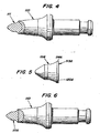
- a hard alloy cap 111 for use in a steel tool body 10 defines a longitudinal axis L.
- the cap 111 includes a conical tip 112, and a base 113 which is intended to rest on a front supporting surface 14 of the tool body 10.
- the base 113 includes a cylindrical outer peripheral surface 114, and a projection forming a rearwardly facing contact surface 120 brazed to the supporting surface 14.
- the cutting cap 111 includes an intermediate portion 115 located between the tip 112 and the base 113.
- the base 113 protects the portion of the tool body 10 that surrounds the cap from excessive wear.
- the intermediate portion 115 comprises a cylindrical intermediate surface 117" adjoining the tip 112, and a concave surface portion 117' extending from the intermediate surface 117" to the front end of the base 113.
- Fig. 3 the following dimensions are represented:
- the d D ratio greater than or equal to 0.7
- the H D ratio equal to or greater than 1.0
- Those ratios make the cap more economical by reducing the cap volume, i.e., the amount of expensive hard alloy (e.g., tungsten carbide-cobalt alloy) that must be used to make the cap.
- the ratios also keep the tool sharper, thereby increasing tool life by maintaining lower cutting forces for a longer period.
- intermediate portion 115 has been depicted as including a cylindrical portion 117", that portion 117" could be deleted and replaced by an extension of the concave surface 117', which extension would be substantially parallel to the axis L at the place where it intersects the tip 112.
- a modified form of a cap 111A is depicted in Figs. 5 and 6.
- the cap 111A corresponds to the cap 111, except that the base 113A does not include a rearward projection.
- the surface 120A that is brazed to the tool body 110 extends perpendicularly to the axis L and intersects the rear end of the cylindrical surface 114A of the base 113A.
Landscapes
- Engineering & Computer Science (AREA)
- Mining & Mineral Resources (AREA)
- Geology (AREA)
- Life Sciences & Earth Sciences (AREA)
- General Life Sciences & Earth Sciences (AREA)
- Geochemistry & Mineralogy (AREA)
- Mechanical Engineering (AREA)
- Drilling And Exploitation, And Mining Machines And Methods (AREA)
- Earth Drilling (AREA)
- Devices For Opening Bottles Or Cans (AREA)
- Crushing And Pulverization Processes (AREA)
- Milling Processes (AREA)
- Turning (AREA)
- Drilling Tools (AREA)
Applications Claiming Priority (3)
| Application Number | Priority Date | Filing Date | Title |
|---|---|---|---|
| US425217 | 1999-10-22 | ||
| US09/425,217 US6270165B1 (en) | 1999-10-22 | 1999-10-22 | Cutting tool for breaking hard material, and a cutting cap therefor |
| PCT/SE2000/001984 WO2001029374A1 (en) | 1999-10-22 | 2000-10-13 | Cutting tool for breaking hard material, and a cutting cap therefor |
Publications (2)
| Publication Number | Publication Date |
|---|---|
| EP1222362A1 EP1222362A1 (en) | 2002-07-17 |
| EP1222362B1 true EP1222362B1 (en) | 2006-04-05 |
Family
ID=23685657
Family Applications (1)
| Application Number | Title | Priority Date | Filing Date |
|---|---|---|---|
| EP00973293A Expired - Lifetime EP1222362B1 (en) | 1999-10-22 | 2000-10-13 | Cutting tool for breaking hard material, and a cutting cap therefor |
Country Status (9)
| Country | Link |
|---|---|
| US (1) | US6270165B1 (enExample) |
| EP (1) | EP1222362B1 (enExample) |
| JP (1) | JP2003512551A (enExample) |
| AT (1) | ATE322609T1 (enExample) |
| AU (1) | AU777065B2 (enExample) |
| CA (1) | CA2387046C (enExample) |
| DE (1) | DE60027186T2 (enExample) |
| WO (1) | WO2001029374A1 (enExample) |
| ZA (1) | ZA200202745B (enExample) |
Families Citing this family (84)
| Publication number | Priority date | Publication date | Assignee | Title |
|---|---|---|---|---|
| DE19922208C2 (de) * | 1999-05-14 | 2002-02-21 | Betek Bergbau & Hartmetall | Rundschaftmeißel |
| US20030209366A1 (en) * | 2002-05-07 | 2003-11-13 | Mcalvain Bruce William | Rotatable point-attack bit with protective body |
| US20040026983A1 (en) * | 2002-08-07 | 2004-02-12 | Mcalvain Bruce William | Monolithic point-attack bit |
| JP4608433B2 (ja) * | 2003-09-05 | 2011-01-12 | 新庄金属工業株式会社 | 回転切削工具およびこれを用いた切削方法 |
| US8109349B2 (en) | 2006-10-26 | 2012-02-07 | Schlumberger Technology Corporation | Thick pointed superhard material |
| US7665552B2 (en) | 2006-10-26 | 2010-02-23 | Hall David R | Superhard insert with an interface |
| US7353893B1 (en) | 2006-10-26 | 2008-04-08 | Hall David R | Tool with a large volume of a superhard material |
| US7740414B2 (en) | 2005-03-01 | 2010-06-22 | Hall David R | Milling apparatus for a paved surface |
| US7950746B2 (en) | 2006-06-16 | 2011-05-31 | Schlumberger Technology Corporation | Attack tool for degrading materials |
| US7469972B2 (en) * | 2006-06-16 | 2008-12-30 | Hall David R | Wear resistant tool |
| US7568770B2 (en) | 2006-06-16 | 2009-08-04 | Hall David R | Superhard composite material bonded to a steel body |
| US7946657B2 (en) * | 2006-08-11 | 2011-05-24 | Schlumberger Technology Corporation | Retention for an insert |
| US7338135B1 (en) | 2006-08-11 | 2008-03-04 | Hall David R | Holder for a degradation assembly |
| USD566137S1 (en) | 2006-08-11 | 2008-04-08 | Hall David R | Pick bolster |
| US7637574B2 (en) * | 2006-08-11 | 2009-12-29 | Hall David R | Pick assembly |
| USD581952S1 (en) | 2006-08-11 | 2008-12-02 | Hall David R | Pick |
| US7669674B2 (en) * | 2006-08-11 | 2010-03-02 | Hall David R | Degradation assembly |
| US8136887B2 (en) * | 2006-08-11 | 2012-03-20 | Schlumberger Technology Corporation | Non-rotating pick with a pressed in carbide segment |
| US7410221B2 (en) * | 2006-08-11 | 2008-08-12 | Hall David R | Retainer sleeve in a degradation assembly |
| US7464993B2 (en) * | 2006-08-11 | 2008-12-16 | Hall David R | Attack tool |
| US9145742B2 (en) | 2006-08-11 | 2015-09-29 | Schlumberger Technology Corporation | Pointed working ends on a drill bit |
| US8567532B2 (en) | 2006-08-11 | 2013-10-29 | Schlumberger Technology Corporation | Cutting element attached to downhole fixed bladed bit at a positive rake angle |
| US7648210B2 (en) | 2006-08-11 | 2010-01-19 | Hall David R | Pick with an interlocked bolster |
| US7387345B2 (en) | 2006-08-11 | 2008-06-17 | Hall David R | Lubricating drum |
| US9051795B2 (en) | 2006-08-11 | 2015-06-09 | Schlumberger Technology Corporation | Downhole drill bit |
| US7963617B2 (en) * | 2006-08-11 | 2011-06-21 | Schlumberger Technology Corporation | Degradation assembly |
| US7722127B2 (en) | 2006-08-11 | 2010-05-25 | Schlumberger Technology Corporation | Pick shank in axial tension |
| US8714285B2 (en) | 2006-08-11 | 2014-05-06 | Schlumberger Technology Corporation | Method for drilling with a fixed bladed bit |
| US7384105B2 (en) | 2006-08-11 | 2008-06-10 | Hall David R | Attack tool |
| US8622155B2 (en) | 2006-08-11 | 2014-01-07 | Schlumberger Technology Corporation | Pointed diamond working ends on a shear bit |
| US8449040B2 (en) | 2006-08-11 | 2013-05-28 | David R. Hall | Shank for an attack tool |
| US7413256B2 (en) | 2006-08-11 | 2008-08-19 | Hall David R | Washer for a degradation assembly |
| US8215420B2 (en) | 2006-08-11 | 2012-07-10 | Schlumberger Technology Corporation | Thermally stable pointed diamond with increased impact resistance |
| US7469971B2 (en) * | 2006-08-11 | 2008-12-30 | Hall David R | Lubricated pick |
| US7419224B2 (en) | 2006-08-11 | 2008-09-02 | Hall David R | Sleeve in a degradation assembly |
| US7320505B1 (en) | 2006-08-11 | 2008-01-22 | Hall David R | Attack tool |
| US8123302B2 (en) | 2006-08-11 | 2012-02-28 | Schlumberger Technology Corporation | Impact tool |
| US7390066B2 (en) * | 2006-08-11 | 2008-06-24 | Hall David R | Method for providing a degradation drum |
| US7832809B2 (en) * | 2006-08-11 | 2010-11-16 | Schlumberger Technology Corporation | Degradation assembly shield |
| US7669938B2 (en) | 2006-08-11 | 2010-03-02 | Hall David R | Carbide stem press fit into a steel body of a pick |
| US7445294B2 (en) | 2006-08-11 | 2008-11-04 | Hall David R | Attack tool |
| US7871133B2 (en) | 2006-08-11 | 2011-01-18 | Schlumberger Technology Corporation | Locking fixture |
| US7992944B2 (en) * | 2006-08-11 | 2011-08-09 | Schlumberger Technology Corporation | Manually rotatable tool |
| US7600823B2 (en) * | 2006-08-11 | 2009-10-13 | Hall David R | Pick assembly |
| US8500210B2 (en) | 2006-08-11 | 2013-08-06 | Schlumberger Technology Corporation | Resilient pick shank |
| US8453497B2 (en) * | 2006-08-11 | 2013-06-04 | Schlumberger Technology Corporation | Test fixture that positions a cutting element at a positive rake angle |
| US7661765B2 (en) | 2006-08-11 | 2010-02-16 | Hall David R | Braze thickness control |
| US7997661B2 (en) * | 2006-08-11 | 2011-08-16 | Schlumberger Technology Corporation | Tapered bore in a pick |
| US8590644B2 (en) | 2006-08-11 | 2013-11-26 | Schlumberger Technology Corporation | Downhole drill bit |
| US8292372B2 (en) | 2007-12-21 | 2012-10-23 | Hall David R | Retention for holder shank |
| US7413258B2 (en) | 2006-08-11 | 2008-08-19 | Hall David R | Hollow pick shank |
| US8500209B2 (en) | 2006-08-11 | 2013-08-06 | Schlumberger Technology Corporation | Manually rotatable tool |
| US8007051B2 (en) | 2006-08-11 | 2011-08-30 | Schlumberger Technology Corporation | Shank assembly |
| US8201892B2 (en) * | 2006-08-11 | 2012-06-19 | Hall David R | Holder assembly |
| US8414085B2 (en) | 2006-08-11 | 2013-04-09 | Schlumberger Technology Corporation | Shank assembly with a tensioned element |
| US7396086B1 (en) | 2007-03-15 | 2008-07-08 | Hall David R | Press-fit pick |
| US8485609B2 (en) | 2006-08-11 | 2013-07-16 | Schlumberger Technology Corporation | Impact tool |
| US8960337B2 (en) | 2006-10-26 | 2015-02-24 | Schlumberger Technology Corporation | High impact resistant tool with an apex width between a first and second transitions |
| US9068410B2 (en) | 2006-10-26 | 2015-06-30 | Schlumberger Technology Corporation | Dense diamond body |
| DE102007009711B4 (de) | 2007-02-28 | 2010-05-20 | Betek Bergbau- Und Hartmetalltechnik Karl-Heinz Simon Gmbh & Co. Kg | Rundschaftmeißel |
| US9051794B2 (en) | 2007-04-12 | 2015-06-09 | Schlumberger Technology Corporation | High impact shearing element |
| US7594703B2 (en) * | 2007-05-14 | 2009-09-29 | Hall David R | Pick with a reentrant |
| US7926883B2 (en) * | 2007-05-15 | 2011-04-19 | Schlumberger Technology Corporation | Spring loaded pick |
| US8038223B2 (en) * | 2007-09-07 | 2011-10-18 | Schlumberger Technology Corporation | Pick with carbide cap |
| US8678517B2 (en) | 2007-08-23 | 2014-03-25 | Sandvik Intellectual Property Ab | Reduced volume cutting tip and cutting bit incorporating same |
| US8210618B2 (en) * | 2007-08-23 | 2012-07-03 | Sandvik Intellectual Property Ab | Reduced volume cutting tip and cutter bit assembly incorporating same |
| US7832808B2 (en) | 2007-10-30 | 2010-11-16 | Hall David R | Tool holder sleeve |
| US20110254349A1 (en) | 2007-12-21 | 2011-10-20 | Hall David R | Resilent Connection between a Pick Shank and Block |
| US8540037B2 (en) | 2008-04-30 | 2013-09-24 | Schlumberger Technology Corporation | Layered polycrystalline diamond |
| US7628233B1 (en) | 2008-07-23 | 2009-12-08 | Hall David R | Carbide bolster |
| US20100018776A1 (en) * | 2008-07-28 | 2010-01-28 | Keller Donald E | Cutting bit for mining and excavating tools |
| US8061457B2 (en) | 2009-02-17 | 2011-11-22 | Schlumberger Technology Corporation | Chamfered pointed enhanced diamond insert |
| US8322796B2 (en) * | 2009-04-16 | 2012-12-04 | Schlumberger Technology Corporation | Seal with contact element for pick shield |
| US8701799B2 (en) * | 2009-04-29 | 2014-04-22 | Schlumberger Technology Corporation | Drill bit cutter pocket restitution |
| US8261471B2 (en) | 2010-06-30 | 2012-09-11 | Hall David R | Continuously adjusting resultant force in an excavating assembly |
| USD640291S1 (en) * | 2010-10-11 | 2011-06-21 | The Charles Machine Works, Inc. | Conical cutting element |
| CA2757795A1 (en) * | 2011-01-03 | 2012-07-03 | Sandvik Intellectual Property Ab | Polygon-shaped carbide tool pick |
| US8728382B2 (en) | 2011-03-29 | 2014-05-20 | David R. Hall | Forming a polycrystalline ceramic in multiple sintering phases |
| US8668275B2 (en) | 2011-07-06 | 2014-03-11 | David R. Hall | Pick assembly with a contiguous spinal region |
| BR112016026762A8 (pt) | 2014-05-19 | 2021-05-04 | Ilr Safety Cc | dispositivo de punção, e, instalação de envidraçamento múltiplo |
| WO2016014139A1 (en) * | 2014-07-24 | 2016-01-28 | Hall David R | Angled degradation pick |
| DE102015112988A1 (de) * | 2015-08-06 | 2017-02-09 | Betek Gmbh & Co. Kg | Schneideinrichtung |
| USD818507S1 (en) | 2017-02-28 | 2018-05-22 | Kennametal Inc | Replaceable tip for a rotatable cutting tool |
| DE102018109148A1 (de) * | 2018-04-17 | 2019-10-17 | Betek Gmbh & Co. Kg | Fräsmeißel |
Family Cites Families (12)
| Publication number | Priority date | Publication date | Assignee | Title |
|---|---|---|---|---|
| SE450259C (sv) | 1983-03-23 | 1996-07-22 | Sandvik Ab | Verktyg för brytning eller avverkning av fasta material, såsom asfalt |
| US4893875A (en) * | 1988-12-16 | 1990-01-16 | Caterpillar Inc. | Ground engaging bit having a hardened tip |
| SE463573B (sv) * | 1989-04-24 | 1990-12-10 | Sandvik Ab | Verktyg samt verktygskropp foer brytning av fasta material |
| US4981328A (en) * | 1989-08-22 | 1991-01-01 | Kennametal Inc. | Rotatable tool having a carbide insert with bumps |
| US5131725A (en) * | 1990-09-04 | 1992-07-21 | Kennametal Inc. | Rotatable cutting tool having an insert with flanges |
| US5219209A (en) * | 1992-06-11 | 1993-06-15 | Kennametal Inc. | Rotatable cutting bit insert |
| US5837071A (en) * | 1993-11-03 | 1998-11-17 | Sandvik Ab | Diamond coated cutting tool insert and method of making same |
| ZA948306B (en) * | 1993-11-03 | 1995-06-22 | Sandvik Ab | Diamond/boron nitride coated excavating tool cutting insert |
| AU3822495A (en) * | 1994-10-28 | 1996-05-31 | I.N. Frantsevich Institute For Problems Of Materials Science | Cutting insert |
| US5503463A (en) * | 1994-12-23 | 1996-04-02 | Rogers Tool Works, Inc. | Retainer scheme for cutting tool |
| EP0757157A4 (en) * | 1995-02-16 | 1999-01-07 | Tovarschestvo Sogranichennoi O | Instrument for breaking up solid material |
| US5823632A (en) * | 1996-06-13 | 1998-10-20 | Burkett; Kenneth H. | Self-sharpening nosepiece with skirt for attack tools |
-
1999
- 1999-10-22 US US09/425,217 patent/US6270165B1/en not_active Expired - Lifetime
-
2000
- 2000-10-13 AT AT00973293T patent/ATE322609T1/de not_active IP Right Cessation
- 2000-10-13 JP JP2001532338A patent/JP2003512551A/ja active Pending
- 2000-10-13 CA CA002387046A patent/CA2387046C/en not_active Expired - Fee Related
- 2000-10-13 DE DE60027186T patent/DE60027186T2/de not_active Expired - Lifetime
- 2000-10-13 AU AU11821/01A patent/AU777065B2/en not_active Expired
- 2000-10-13 EP EP00973293A patent/EP1222362B1/en not_active Expired - Lifetime
- 2000-10-13 WO PCT/SE2000/001984 patent/WO2001029374A1/en not_active Ceased
-
2002
- 2002-04-08 ZA ZA200202745A patent/ZA200202745B/en unknown
Also Published As
| Publication number | Publication date |
|---|---|
| US6270165B1 (en) | 2001-08-07 |
| JP2003512551A (ja) | 2003-04-02 |
| ATE322609T1 (de) | 2006-04-15 |
| CA2387046A1 (en) | 2001-04-26 |
| CA2387046C (en) | 2008-04-29 |
| AU777065B2 (en) | 2004-09-30 |
| DE60027186D1 (de) | 2006-05-18 |
| EP1222362A1 (en) | 2002-07-17 |
| ZA200202745B (en) | 2003-09-23 |
| AU1182101A (en) | 2001-04-30 |
| DE60027186T2 (de) | 2006-08-24 |
| WO2001029374A1 (en) | 2001-04-26 |
Similar Documents
| Publication | Publication Date | Title |
|---|---|---|
| EP1222362B1 (en) | Cutting tool for breaking hard material, and a cutting cap therefor | |
| US4938538A (en) | Excavating tool cutting insert | |
| US5161859A (en) | Excavating tool cutting insert | |
| EP1266125B1 (en) | Rotatable cutting tool | |
| CN101889127B (zh) | 具有烧结的碳化钨刀片和环的破碎或挖掘刀具、结合这种刀具的材料去除机和制造这种刀具的方法 | |
| US5823632A (en) | Self-sharpening nosepiece with skirt for attack tools | |
| US4678237A (en) | Cutter inserts for picks | |
| US6477796B1 (en) | Tooth assembly for implements | |
| US5415462A (en) | Rotatable cutting bit and bit holder | |
| US3945681A (en) | Cutter assembly | |
| USH2020H1 (en) | Tip and adapter for an earthworking bucket | |
| US6478383B1 (en) | Rotatable cutting tool-tool holder assembly | |
| CA2150246C (en) | Cutting tool having hard tip with lobes | |
| JP4485705B2 (ja) | 掘削用ビット及びケーシングカッタ | |
| WO2011037799A1 (en) | Rotatable cutting tool with hard cutting member | |
| CA2076437A1 (en) | Tools | |
| EP0651133A2 (en) | Diamond/boron nitride coated excavating tool cutting insert | |
| WO1996013968A2 (en) | Cutting insert for a cutting tool | |
| CA1224028A (en) | Excavating tool | |
| JP4485706B2 (ja) | 両方向掘削ビット及びケーシングカッタ | |
| JPH11210379A (ja) | トンネル掘進機のカッタービット及びカッターヘッド | |
| AU592911B2 (en) | Erosion resistant cutting bit with hardfacing | |
| JPS632550Y2 (enExample) |
Legal Events
| Date | Code | Title | Description |
|---|---|---|---|
| PUAI | Public reference made under article 153(3) epc to a published international application that has entered the european phase |
Free format text: ORIGINAL CODE: 0009012 |
|
| 17P | Request for examination filed |
Effective date: 20020323 |
|
| AK | Designated contracting states |
Kind code of ref document: A1 Designated state(s): AT BE CH CY DE DK ES FI FR GB GR IE IT LI LU MC NL PT SE |
|
| AX | Request for extension of the european patent |
Free format text: AL;LT;LV;MK;RO;SI |
|
| 17Q | First examination report despatched |
Effective date: 20050428 |
|
| GRAP | Despatch of communication of intention to grant a patent |
Free format text: ORIGINAL CODE: EPIDOSNIGR1 |
|
| RAP1 | Party data changed (applicant data changed or rights of an application transferred) |
Owner name: SANDVIK INTELLECTUAL PROPERTY AB |
|
| GRAS | Grant fee paid |
Free format text: ORIGINAL CODE: EPIDOSNIGR3 |
|
| GRAA | (expected) grant |
Free format text: ORIGINAL CODE: 0009210 |
|
| AK | Designated contracting states |
Kind code of ref document: B1 Designated state(s): AT BE CH CY DE DK ES FI FR GB GR IE IT LI LU MC NL PT SE |
|
| PG25 | Lapsed in a contracting state [announced via postgrant information from national office to epo] |
Ref country code: FI Free format text: LAPSE BECAUSE OF FAILURE TO SUBMIT A TRANSLATION OF THE DESCRIPTION OR TO PAY THE FEE WITHIN THE PRESCRIBED TIME-LIMIT Effective date: 20060405 Ref country code: AT Free format text: LAPSE BECAUSE OF FAILURE TO SUBMIT A TRANSLATION OF THE DESCRIPTION OR TO PAY THE FEE WITHIN THE PRESCRIBED TIME-LIMIT Effective date: 20060405 Ref country code: NL Free format text: LAPSE BECAUSE OF FAILURE TO SUBMIT A TRANSLATION OF THE DESCRIPTION OR TO PAY THE FEE WITHIN THE PRESCRIBED TIME-LIMIT Effective date: 20060405 Ref country code: LI Free format text: LAPSE BECAUSE OF FAILURE TO SUBMIT A TRANSLATION OF THE DESCRIPTION OR TO PAY THE FEE WITHIN THE PRESCRIBED TIME-LIMIT Effective date: 20060405 Ref country code: BE Free format text: LAPSE BECAUSE OF FAILURE TO SUBMIT A TRANSLATION OF THE DESCRIPTION OR TO PAY THE FEE WITHIN THE PRESCRIBED TIME-LIMIT Effective date: 20060405 Ref country code: CH Free format text: LAPSE BECAUSE OF FAILURE TO SUBMIT A TRANSLATION OF THE DESCRIPTION OR TO PAY THE FEE WITHIN THE PRESCRIBED TIME-LIMIT Effective date: 20060405 Ref country code: IT Free format text: LAPSE BECAUSE OF FAILURE TO SUBMIT A TRANSLATION OF THE DESCRIPTION OR TO PAY THE FEE WITHIN THE PRESCRIBED TIME-LIMIT;WARNING: LAPSES OF ITALIAN PATENTS WITH EFFECTIVE DATE BEFORE 2007 MAY HAVE OCCURRED AT ANY TIME BEFORE 2007. THE CORRECT EFFECTIVE DATE MAY BE DIFFERENT FROM THE ONE RECORDED. Effective date: 20060405 |
|
| REG | Reference to a national code |
Ref country code: GB Ref legal event code: FG4D |
|
| REG | Reference to a national code |
Ref country code: CH Ref legal event code: EP |
|
| REG | Reference to a national code |
Ref country code: IE Ref legal event code: FG4D |
|
| REF | Corresponds to: |
Ref document number: 60027186 Country of ref document: DE Date of ref document: 20060518 Kind code of ref document: P |
|
| PG25 | Lapsed in a contracting state [announced via postgrant information from national office to epo] |
Ref country code: SE Free format text: LAPSE BECAUSE OF FAILURE TO SUBMIT A TRANSLATION OF THE DESCRIPTION OR TO PAY THE FEE WITHIN THE PRESCRIBED TIME-LIMIT Effective date: 20060705 Ref country code: DK Free format text: LAPSE BECAUSE OF FAILURE TO SUBMIT A TRANSLATION OF THE DESCRIPTION OR TO PAY THE FEE WITHIN THE PRESCRIBED TIME-LIMIT Effective date: 20060705 |
|
| PG25 | Lapsed in a contracting state [announced via postgrant information from national office to epo] |
Ref country code: ES Free format text: LAPSE BECAUSE OF FAILURE TO SUBMIT A TRANSLATION OF THE DESCRIPTION OR TO PAY THE FEE WITHIN THE PRESCRIBED TIME-LIMIT Effective date: 20060716 |
|
| PG25 | Lapsed in a contracting state [announced via postgrant information from national office to epo] |
Ref country code: PT Free format text: LAPSE BECAUSE OF FAILURE TO SUBMIT A TRANSLATION OF THE DESCRIPTION OR TO PAY THE FEE WITHIN THE PRESCRIBED TIME-LIMIT Effective date: 20060905 |
|
| NLV1 | Nl: lapsed or annulled due to failure to fulfill the requirements of art. 29p and 29m of the patents act | ||
| PG25 | Lapsed in a contracting state [announced via postgrant information from national office to epo] |
Ref country code: IE Free format text: LAPSE BECAUSE OF NON-PAYMENT OF DUE FEES Effective date: 20061013 |
|
| REG | Reference to a national code |
Ref country code: CH Ref legal event code: PL |
|
| PG25 | Lapsed in a contracting state [announced via postgrant information from national office to epo] |
Ref country code: MC Free format text: LAPSE BECAUSE OF NON-PAYMENT OF DUE FEES Effective date: 20061031 |
|
| ET | Fr: translation filed | ||
| PLBE | No opposition filed within time limit |
Free format text: ORIGINAL CODE: 0009261 |
|
| STAA | Information on the status of an ep patent application or granted ep patent |
Free format text: STATUS: NO OPPOSITION FILED WITHIN TIME LIMIT |
|
| 26N | No opposition filed |
Effective date: 20070108 |
|
| PG25 | Lapsed in a contracting state [announced via postgrant information from national office to epo] |
Ref country code: GR Free format text: LAPSE BECAUSE OF FAILURE TO SUBMIT A TRANSLATION OF THE DESCRIPTION OR TO PAY THE FEE WITHIN THE PRESCRIBED TIME-LIMIT Effective date: 20060706 |
|
| PG25 | Lapsed in a contracting state [announced via postgrant information from national office to epo] |
Ref country code: LU Free format text: LAPSE BECAUSE OF NON-PAYMENT OF DUE FEES Effective date: 20061013 |
|
| PG25 | Lapsed in a contracting state [announced via postgrant information from national office to epo] |
Ref country code: CY Free format text: LAPSE BECAUSE OF FAILURE TO SUBMIT A TRANSLATION OF THE DESCRIPTION OR TO PAY THE FEE WITHIN THE PRESCRIBED TIME-LIMIT Effective date: 20060405 |
|
| PGFP | Annual fee paid to national office [announced via postgrant information from national office to epo] |
Ref country code: FR Payment date: 20131009 Year of fee payment: 14 |
|
| PGFP | Annual fee paid to national office [announced via postgrant information from national office to epo] |
Ref country code: IT Payment date: 20131015 Year of fee payment: 14 |
|
| PGFP | Annual fee paid to national office [announced via postgrant information from national office to epo] |
Ref country code: GB Payment date: 20141008 Year of fee payment: 15 Ref country code: DE Payment date: 20141007 Year of fee payment: 15 |
|
| REG | Reference to a national code |
Ref country code: FR Ref legal event code: ST Effective date: 20150630 |
|
| PG25 | Lapsed in a contracting state [announced via postgrant information from national office to epo] |
Ref country code: FR Free format text: LAPSE BECAUSE OF NON-PAYMENT OF DUE FEES Effective date: 20141031 Ref country code: IT Free format text: LAPSE BECAUSE OF NON-PAYMENT OF DUE FEES Effective date: 20141013 |
|
| REG | Reference to a national code |
Ref country code: DE Ref legal event code: R119 Ref document number: 60027186 Country of ref document: DE |
|
| GBPC | Gb: european patent ceased through non-payment of renewal fee |
Effective date: 20151013 |
|
| PG25 | Lapsed in a contracting state [announced via postgrant information from national office to epo] |
Ref country code: GB Free format text: LAPSE BECAUSE OF NON-PAYMENT OF DUE FEES Effective date: 20151013 Ref country code: DE Free format text: LAPSE BECAUSE OF NON-PAYMENT OF DUE FEES Effective date: 20160503 |