EP1220806B1 - System for the controlled lubrication of conveyors - Google Patents
System for the controlled lubrication of conveyors Download PDFInfo
- Publication number
- EP1220806B1 EP1220806B1 EP00968657A EP00968657A EP1220806B1 EP 1220806 B1 EP1220806 B1 EP 1220806B1 EP 00968657 A EP00968657 A EP 00968657A EP 00968657 A EP00968657 A EP 00968657A EP 1220806 B1 EP1220806 B1 EP 1220806B1
- Authority
- EP
- European Patent Office
- Prior art keywords
- conveyor
- lubricant
- belt
- microprocessor
- applicator
- Prior art date
- Legal status (The legal status is an assumption and is not a legal conclusion. Google has not performed a legal analysis and makes no representation as to the accuracy of the status listed.)
- Expired - Lifetime
Links
Images

Classifications
-
- B—PERFORMING OPERATIONS; TRANSPORTING
- B65—CONVEYING; PACKING; STORING; HANDLING THIN OR FILAMENTARY MATERIAL
- B65G—TRANSPORT OR STORAGE DEVICES, e.g. CONVEYORS FOR LOADING OR TIPPING, SHOP CONVEYOR SYSTEMS OR PNEUMATIC TUBE CONVEYORS
- B65G45/00—Lubricating, cleaning, or clearing devices
- B65G45/02—Lubricating devices
-
- B—PERFORMING OPERATIONS; TRANSPORTING
- B65—CONVEYING; PACKING; STORING; HANDLING THIN OR FILAMENTARY MATERIAL
- B65G—TRANSPORT OR STORAGE DEVICES, e.g. CONVEYORS FOR LOADING OR TIPPING, SHOP CONVEYOR SYSTEMS OR PNEUMATIC TUBE CONVEYORS
- B65G45/00—Lubricating, cleaning, or clearing devices
- B65G45/10—Cleaning devices
- B65G45/22—Cleaning devices comprising fluid applying means
-
- B—PERFORMING OPERATIONS; TRANSPORTING
- B65—CONVEYING; PACKING; STORING; HANDLING THIN OR FILAMENTARY MATERIAL
- B65G—TRANSPORT OR STORAGE DEVICES, e.g. CONVEYORS FOR LOADING OR TIPPING, SHOP CONVEYOR SYSTEMS OR PNEUMATIC TUBE CONVEYORS
- B65G2201/00—Indexing codes relating to handling devices, e.g. conveyors, characterised by the type of product or load being conveyed or handled
- B65G2201/02—Articles
- B65G2201/0202—Agricultural and processed food products
- B65G2201/0211—Fruits and vegetables
Definitions
- the invention relates to a conveyor lubricating system for application of lubricant onto a conveyor, the conveyor used for moving items on a belt and having a track, the lubrication system comprising: a lubricant source, a lubricant applicator for application of the lubricant onto the conveyor, and a control system.
- 5,372,243 provides an alternative to the above described cleaning method.
- King teaches a pneumatically controlled cleaning and rinsing system for conveyors.
- the valves for providing cleaning and rinsing ingredients are pneumatically actuated, as are the timers and sequencer valves.
- Pneumatically controlled and actuated equipment is stressed because of the desire to eliminate corrosion of electrical equipment and components in wet environments.
- U.S. Patent No. 5,129,481 describes an apparatus and method for lubricating conveyors and belts used in the food industry comprising a device including valves which are alternately opened and closed by an actuating device driven from the conveyor movement. The valves supply a lubricant which is fed to output nozzles for spraying onto the conveyors for lubricating purposes, and the valves will only feed lubricant when the conveyor is moving.
- U.S. Patent No. 5,289,899 teaches an air-driven delay valve or relay, which is driven from the conveyor system, and which connects to a counter which controls the valve that passes lubricant in a pulsating or intermittent fashion.
- pneumatically controlled systems such as those described above, can be inaccurate, for example, in their time measurement and fluid dispensing, leading to ineffective cleaning and/or lubricating of the conveyor and wasted supplies.
- the amount of lubricant is controlled in dependence of the speed of the conveyor and/or the type and size of the objects, such as bottles, glass or plastic, cans, bags.
- the invention has for its object to improve the known system and to that effect provides a system of the above-mentioned type wherein the control system is characterized by (i) a first sensing system to sense movement of the belt; (ii) a second sensing system to sense presence of objects on the belt; (iii) a microprocessor to open a nozzle to spray lubricant onto the conveyor; wherein if the first sensing system confirms movement of the belt and the second sensing system confirms an object, the microprocessor provides a signal to open the lubricant applicator so that a first amount of lubricant is fed from the lubricant source and is applied onto the conveyor; and if the first sensing system confirms movement but the second sensing system does not confirm an object, the microprocessor provides a signal to open the lubricant applicator so that a second amount of lubricant is fed from the lubricant source and is applied to the conveyor, the second amount of lubricant being less than the first amount; and
- the present invention relates to a new and improved system for lubricating conveyor systems using a microprocessor controlled control system.
- the control system senses movement of the conveyor belt and the presence of any items, such as cans, bottles, or food products, on the conveyor belt, and in return either cleans or lubricates the conveyor as needed.
- This automated system reduces the amount of labor needed to perform these critical tasks, as well as reduces the amount of wasted lubricating supplies.
- the present invention relates to a conveyor system that includes the combination of a conveyor system, a washing system, and a lubrication system.
- the conveyor system is for transporting an object, with the conveyor system including a conveyor belt having a front side and a back side, and a drive mechanism for providing movement to the belt.
- the washing system is for rinsing and washing the conveyor belt and includes a water source, a detergent source, a mixing chamber to mix the water and the detergent to form a cleaning solution, and an applicator for application of the cleaning solution onto the belt.
- the applicator is a spray nozzle.
- the application of the cleaning solution onto the belt is controlled by a control system, which comprises a microprocessor adapted to provide a signal to open the applicator to provide rinse or cleaning solution onto the belt.
- the lubrication system is for lubricating the conveyor belt to improve belt tracking and to extend the useable life of the belt.
- the lubrication system includes a lubricant source and an applicator for application of the lubricant onto the belt.
- the applicator is a spray nozzle.
- the application of the lubricant onto the belt is controlled by a lubricant control system that includes a first sensing system to sense movement of the belt, a second sensing system to sense presence of items on the belt, and a control system comprising a microprocessor that receives signals from the sensing systems and sends signals to open the applicator to provide lubricant onto the belt on a predetermined, timed basis.
- a lubricant control system that includes a first sensing system to sense movement of the belt, a second sensing system to sense presence of items on the belt, and a control system comprising a microprocessor that receives signals from the sensing systems and sends signals to open the applicator to provide lubricant onto the belt on a predetermined, timed basis.
- the amount of lubricant applied to the belt is dependent on the signals from the first and second sensing systems.
- the microprocessor provides a signal to provide lubricant so that a first amount of lubricant is fed from the lubricant source and is applied onto the conveyor. If the first sensing system confirms movement of the belt but the second sensing system does not confirm the presence of an object, the microprocessor provides a signal to provide lubricant so that a second amount of lubricant is fed from the lubricant source and is applied to the conveyor, the second amount of lubricant being less than the first amount. If the first sensing system does not confirm movement, whether or not items are present on the belt, the microprocessor does not provide a signal to apply lubricant.
- the washing system comprises a microprocessor to provide a signal to apply a rinse or cleaning solution to the conveyor belt for a predetermined time interval.
- this washing process occurs after any production run on the conveyor system is complete.
- the washing process generally includes a first rinse step, a cleaning step, and a second rinse step.
- the invention relates to a system for lubricating conveyors using a microprocessor controlled control system.
- the control system senses the activity of the conveyor and the presence of items on the conveyor, and in return either cleans or lubricates the conveyor as needed. If the control system only senses movement of the conveyor but no item on the conveyor, only a small amount of lubricant is applied to the conveyor sufficient to keep the conveyor belt properly lubricated.
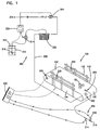
- Figure 1 shows a general arrangement of a conveyor maintenance system 100 that has a lubrication system 200 and a washing system 300.
- the apparatus 100 is used for lubricating and washing a conveyor system 110, although not necessarily simultaneously.
- Conveyor system 110 includes a conveyor belt 120 having a front side 122 and a back side 124, and a structure 115 to support belt 120.
- Front side 122 of belt 120 is the side on which items, such as bottles or cans 50, are carried.
- Back side 124 is the inner side when belt 120 is formed as a loop (as shown in Figure 1), and back side 124 typically contacts a drive mechanism (not shown).
- Conveyor systems, such as those designated as conveyor system 110, are well known.
- Washing system 300 has a water source 302, a detergent source 310, and a device in which the water and the detergent are mixed.
- a mixing device is shown as mixing chamber 320.
- Water source 302 is typically a potable water source and is generally supplied at about 5 to 20 gallons per minute at a pressure of about 60 to 125 psi, although other volumetric rates and pressures could be used.
- Detergent source 310 can be a drum 312, such as a 55 gallon drum, or a larger storage tank.
- the detergent may be any solution, mixture, component or the like used for cleaning, disinfecting, degreasing, etc.
- a low level alarm 316 may be used within detergent source 310 to warn of low detergent supply.
- a controller 305 is used to control valves 304, 314 which allow feed from water source 302 and detergent source 310, respectively, to flow to mixing chamber 320.
- a mixing device for example, mixing chamber 320
- the cleaning mixture or solution is applied to the conveyor belt.
- the solution is supplied via delivery pipe 330 to a detergent applicator, shown as spray nozzle 350 (shown in phantom in Figure 1).
- Spray nozzle 350 applies cleaning solution to back side 124 of conveyor belt 120.
- the cleaning solution could be applied to front side 122 of conveyor belt 120 or other areas of conveyor system 110, such as structure 115.
- a water-only rinse of the conveyor system 110 In some steps during the washing procedure, it may be desired to provide a water-only rinse of the conveyor system 110; that is, no detergent is used.
- the process of washing is considered to comprise rinsing. Rinsing is performed in the same manner as washing, except that typically no detergent is added to provide the solution. There may, however, be additives provide to the water source to produce a rinse solution. Often, a three-step process is used: a first rinse step, a washing or cleaning step, and a second rinse step.
- the washing process which includes the steps of applying rinse and/or cleaning solution, may be applied to conveyor belt 120 at predetermined intervals, for example, a one to three minute rinse after every hour of operation.
- Rinse and/or cleaning solution may also, or alternately, be applied at the end of the production run that uses conveyor system 110, for example, at the end of the work day or shift.
- the conveyor belt 120 may continue to run (i.e., move) during the cleaning operation or may be stopped.
- washing system 300 no sensors are needed in washing system 300 if it is desired to rinse and/or washing conveyor belt 120 after its use.
- the washing may be activated by, for example, a manual switch after the production run has been completed.
- Lubrication system 200 has a lubricant source 210 and a lubricant applicator, such as spray nozzle 250, to apply lubricant to front side 122 of conveyor belt 120.
- the lubricant could be applied to back side 124 of conveyor belt 120.
- the amount of lubricant applied to belt 120 is dependent on both the movement of conveyor belt 120 and the presence of items, such as cans 50, on belt 120. If belt 120 is in motion and items are present on the belt, a first amount of lubricant is applied to front side 122 of belt 120. If belt 120 is in motion and no items are present, a second amount of lubricant is applied, with the second amount of lubricant being less that the first amount. If no movement of belt 120 is sensed, whether or not any items are present on belt 120, no lubricant is applied.
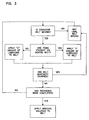
- Figure 3 is a block diagram of the logic used to determine the application of the lubricant.
- Movement of belt 120 is sensed by a sensor 220, which in Figure 1 is positioned to monitor back side 124 of belt 120. Presence of items, such as cans 50, is sensed by sensor 225.
- Figure 1 shows two sensors 225, 225' on opposites sides of belt 120 and mounted on structure 115. Although only one sensor 225 for monitoring the belt and two sensors 225, 225' for monitoring presence of items are shown, any number of sensors can be used.
- Sensors 220, 225, 225' may be any sensors capable of sensing movement and/or presence of items; usable sensors include well known devices such as motion or vibration detectors, or laser, IR or other sensors. In another embodiment, the sensor may be directly wired or otherwise connected to the conveyor system's motor.
- Sensors 220, 225, 225' are connected to a control system 205 which includes a microprocessor (not shown) therein. Signals from sensors 220, 225, 225' are processed by the microprocessor, which then sends a signal to valve 204 which controls supply of lubricant from source 210 to nozzle 250.
- the microprocessor usable in the control system 205 of the present invention may be a programmable general purpose microprocessor, also known as a "PLC” or a programmable logic controller. 'Ladder logic' is typically the format used when programming this microprocessor.
- the microprocessor is incorporated into the control system 205 and may be attached to equipment such as a monitor, touch screen, keyboard, or a mouse. The microprocessor is then also connected to the sensors and valves.
- control system 205 If sensor 220 provides a negative signal to control system 205 indicating that belt 120 is not moving, control system 205 provides a signal to close valve 204 so that no lubricant is applied to belt 120. If sensor 220 provides a positive signal indicating that belt 120 is in motion, and sensor 225 provides a positive signal indicating that items such as cans 50 are present on belt 120, control system 205 provides a signal to open valve 204 so that a first amount of lubricant flows to nozzle 250 and is applied to belt 120.
- control system 205 provides a signal to open valve 204 partially so that a second amount of lubricant flows to nozzle 250 and is applied to belt 120.
- the second amount of lubricant allowed through valve 204 and applied by nozzle 250 is less that the first amount, because no lubrication is need between items and the belt if no items are present.
- the lubrication desired, when no items are present, is a minimal amount, simply to reduce friction and maintain flexibility of the belt.
- Lubricant source 210 can be any container such as a drum, a large storage tank, or can be supplied by a delivery pipe from a remote location.
- Valve 204 is preferably a pneumatic (air actuated) valve and is controlled by signals from control system 205.
- An air injection tee 214 may be included in lubricant system 200 to provide a stream of air to be mixed with the lubricant before it is applied to belt 120.
- a conveyor system 500 is typically divided into multiple zones, generally at least two zones, often more than two zones.
- Figure 2 shows conveyor system 500 with four zones.
- a "zone” is a region or length of conveyor and each zone typically has its own conveyor belt, support framework, conveyor track, and drive mechanism for the conveyor belt. Often, a zone may have multiple conveyor belts that may or may not have their own drive mechanism.
- FIG. 2 is a top simplified schematic diagram of conveyor system 500 divided into four zones.
- Conveyor system 500 includes a filler station 520 where a container, such as a can or bottle, is filled.
- Conveyor belt 510 moves the container from one station, such as filler station 520, to the next station. From filler 520, the container progresses along conveyor belt 510 to seamer station 530 where the container is sealed, e.g., capped. From seamer 530, the container progresses through a warmer station 540. After warmer 540, the container progresses to accumulation area 550, where multiple containers are stored until they are ready to be sent to caser station 560.
- the containers are packaged for delivery and distribution, for example, cans may be packaged in plastic 6-pack rings, or in paperboard boxes for 12 and 24 packs.
- Conveyor system 500 is divided into four zones I, II, III, and IV, which extend from seamer 530 to caser 560.
- Zone I extends from after seamer 530 to warmer 540, but could optionally start at filler 520.
- Zone II extends from after warmer 540 to accumulation area 550.
- conveyor system 500 is divided into two zones, III and IV, which extend to caser station 560.
- each zone may include a system for controlling the lubricant and a system for controlling the rinse and cleaning solutions, the systems may, however, be shared with one or multiple additional zones.
- a single control system is capable of controlling all lubricant systems, without the need for an individual control system for each lubrication system.
- conveyor belt 510 actually may include multiple belts. Typically, each bend or turn in the system requires a new belt.
- conveyor belt 510a extends from filler station 520 to seamer station 530. From seamer 530, two belts 510b, 510c extend to warmer 540. Both belts 510b, 510c are within zone I. From warmer 540, belts 510d, 510e, 510f and 510g in zone II extend to accumulation area 550. Belt 510h in zone III and belt 510I in zone IV extend to caser station 560.
- Each belt 510a, 510b, etc. may have its own drive mechanism (not shown), or multiple belts may share a drive mechanism.
- a single control system with a microprocessor can be used to control all lubricant systems that apply lubricant to belts 510a, 510b, etc.
- a single control system with a microprocessor can be used to control all washing systems.
Landscapes
- Engineering & Computer Science (AREA)
- Mechanical Engineering (AREA)
- Cleaning In General (AREA)
- Control Of Conveyors (AREA)
- Nozzles (AREA)
- Coating Apparatus (AREA)
- Vehicle Cleaning, Maintenance, Repair, Refitting, And Outriggers (AREA)
Applications Claiming Priority (3)
| Application Number | Priority Date | Filing Date | Title |
|---|---|---|---|
| US09/415,941 US6302263B1 (en) | 1999-10-08 | 1999-10-08 | Apparatus and method for the controlled lubrication and cleaning of conveyors |
| US415941 | 1999-10-08 | ||
| PCT/US2000/027345 WO2001027005A1 (en) | 1999-10-08 | 2000-10-04 | Apparatus and method for the controlled lubrication and cleaning of conveyors |
Publications (2)
| Publication Number | Publication Date |
|---|---|
| EP1220806A1 EP1220806A1 (en) | 2002-07-10 |
| EP1220806B1 true EP1220806B1 (en) | 2004-07-14 |
Family
ID=23647865
Family Applications (1)
| Application Number | Title | Priority Date | Filing Date |
|---|---|---|---|
| EP00968657A Expired - Lifetime EP1220806B1 (en) | 1999-10-08 | 2000-10-04 | System for the controlled lubrication of conveyors |
Country Status (8)
| Country | Link |
|---|---|
| US (2) | US6302263B1 (enExample) |
| EP (1) | EP1220806B1 (enExample) |
| JP (1) | JP4913300B2 (enExample) |
| AT (1) | ATE271007T1 (enExample) |
| AU (1) | AU7853800A (enExample) |
| DE (1) | DE60012201T2 (enExample) |
| ES (1) | ES2225230T3 (enExample) |
| WO (1) | WO2001027005A1 (enExample) |
Cited By (2)
| Publication number | Priority date | Publication date | Assignee | Title |
|---|---|---|---|---|
| WO2010063040A3 (en) * | 2008-11-03 | 2010-07-22 | Improchem (Pty) Ltd | Lubricating system monitoring arrangement |
| CN105612115B (zh) * | 2013-08-07 | 2018-08-31 | 雷克斯诺德弗莱托普欧洲有限公司 | 包括摩擦系数测量设备的输送器系统 |
Families Citing this family (38)
| Publication number | Priority date | Publication date | Assignee | Title |
|---|---|---|---|---|
| US20040055965A1 (en) * | 1997-06-13 | 2004-03-25 | Hubig Stephan M. | Recreational water treatment employing singlet oxygen |
| US20030194433A1 (en) * | 2002-03-12 | 2003-10-16 | Ecolab | Antimicrobial compositions, methods and articles employing singlet oxygen- generating agent |
| US6495494B1 (en) | 2000-06-16 | 2002-12-17 | Ecolab Inc. | Conveyor lubricant and method for transporting articles on a conveyor system |
| US6572512B2 (en) * | 2000-08-30 | 2003-06-03 | Brunswick Corporation | Treadmill mechanism |
| US6899659B2 (en) * | 2000-08-30 | 2005-05-31 | Brunswick Corporation | Treadmill mechanism |
| US6302263B1 (en) * | 1999-10-08 | 2001-10-16 | Ecolab, Inc. | Apparatus and method for the controlled lubrication and cleaning of conveyors |
| US7364033B2 (en) * | 1999-11-17 | 2008-04-29 | Ecolab Inc. | Container, such as a food or beverage container, lubrication method |
| US6360874B1 (en) * | 2000-02-10 | 2002-03-26 | Ibp, Inc. | Automated conveyor cleaning system |
| EP1150257A1 (de) * | 2000-04-29 | 2001-10-31 | Prokent AG | Rücknahmeautomat für Leergutbehälter |
| US6530658B1 (en) * | 2000-05-30 | 2003-03-11 | Hewlett-Packard Company | Dispensing applicator and method of use |
| DE20114393U1 (de) * | 2000-09-09 | 2002-01-24 | Lang Apparatebau Gmbh, 83313 Siegsdorf | Vorrichtung zur Aufbringung von versprühbaren Flüssigkeiten |
| DE20015780U1 (de) * | 2000-09-12 | 2000-12-21 | Lincoln GmbH, 69190 Walldorf | Schmieranlage |
| US6591970B2 (en) | 2000-12-13 | 2003-07-15 | Ecolab Inc. | Water-activatable conveyor lubricant and method for transporting articles on a conveyor system |
| US6601693B2 (en) * | 2001-01-16 | 2003-08-05 | The Laitram Corporation | Belt conveyor with a surface layer transferred onto the article-conveying surface and method therefor |
| US6688434B2 (en) * | 2002-02-22 | 2004-02-10 | Ecolab Inc. | Conveyor and lubricating apparatus, lubricant dispensing device, and method for applying lubricant to conveyor |
| US20070020300A1 (en) * | 2002-03-12 | 2007-01-25 | Ecolab Inc. | Recreational water treatment employing singlet oxygen |
| ATE348767T1 (de) * | 2002-10-16 | 2007-01-15 | Johnson Diversey Inc | Automatisiertes förderbandbehandlungssystem |
| GB0325635D0 (en) * | 2003-11-04 | 2003-12-10 | Mcarthur Colin | Lubricating method and apparatus |
| CA2518657A1 (en) * | 2004-09-13 | 2006-03-13 | Inventio Ag | Gravity-fed lubricator for escalators or moving walks |
| US20090264299A1 (en) * | 2006-02-24 | 2009-10-22 | Complete Genomics, Inc. | High throughput genome sequencing on DNA arrays |
| US20070137937A1 (en) * | 2005-11-29 | 2007-06-21 | Guillermo Citro | Conveyor lubricating apparatus |
| EP1932901A1 (en) * | 2006-12-12 | 2008-06-18 | JohnsonDiversey, Inc. | A method of lubricating a conveyor belt |
| EP2105493B1 (en) * | 2008-03-25 | 2014-05-14 | Diversey, Inc. | Dry lubrication method employing oil-based lubricants |
| EP2105494B1 (en) * | 2008-03-25 | 2019-05-08 | Diversey, Inc. | A method of lubricating a conveyor belt |
| KR100892295B1 (ko) | 2008-12-23 | 2009-04-08 | 주식회사 라우텍 | 자가발전장치를 갖는 벨트 컨베이어 |
| KR101017387B1 (ko) * | 2009-01-14 | 2011-02-28 | 도요 고무 고교 가부시키가이샤 | 프로스법 경질 폴리우레탄폼의 제조 장치 |
| US20100243410A1 (en) * | 2009-03-30 | 2010-09-30 | H & H Green,LLC | Method and apparatus for cleaning and sanitizing conveyor belts |
| US8343898B2 (en) * | 2009-12-31 | 2013-01-01 | Ecolab Usa Inc. | Method of lubricating conveyors using oil in water emulsions |
| US8141695B2 (en) * | 2010-01-29 | 2012-03-27 | Ecolab Usa Inc. | Clean conveyor sensing system |
| US20120318297A1 (en) * | 2011-06-16 | 2012-12-20 | Owens Corning Intellectual Capital, Llc | Washing system for cleaning a moving web |
| ES2828986T3 (es) * | 2015-02-02 | 2021-05-28 | Chp N V | Equipo de lubricación en seco para cinta transportadora |
| NL2016340B1 (en) * | 2016-03-01 | 2017-09-11 | Rexnord Flattop Europe Bv | Method and system for transporting products. |
| US20180209585A1 (en) * | 2017-01-24 | 2018-07-26 | Robert McKenna | Treadmill Lubrication System and Method |
| US11390466B1 (en) | 2018-01-17 | 2022-07-19 | James P. Gallagher | Apparatus for use in molecular transfer and delivery of substances such as vapors, gases, liquids, and sprays |
| KR102756683B1 (ko) * | 2022-06-27 | 2025-01-16 | 씨제이대한통운 (주) | 물품 자동 분류장치의 슈트 윤활제 자동 분사 시스템 |
| US20240383697A1 (en) * | 2023-05-17 | 2024-11-21 | Dubois Chemicals, Inc. | System and method for lubricating a conveyor |
| EP4506282A1 (en) | 2023-08-07 | 2025-02-12 | Neo Conveying Intelligence, Unipessoal Lda | A lubrication system for lubricating a conveyor |
| WO2025032520A1 (en) | 2023-08-07 | 2025-02-13 | Neo Conveying Intelligence, Unipessoal Lda | A lubrication system for lubricating a conveyor |
Family Cites Families (24)
| Publication number | Priority date | Publication date | Assignee | Title |
|---|---|---|---|---|
| US4274509A (en) | 1978-05-25 | 1981-06-23 | Madison-Kipp Corporation | Electrical lubricating apparatus |
| US4262776A (en) * | 1978-09-13 | 1981-04-21 | H. B. Fuller Company | Conveyor lubricating system |
| US4226325A (en) | 1979-03-15 | 1980-10-07 | Mcgraw-Edison Company | Conveyor lubricating and washing apparatus |
| US4368803A (en) * | 1980-08-07 | 1983-01-18 | Madison-Kipp Corporation | Apparatus for dispensing fluid onto a moving mechanical system |
| ZA827640B (en) | 1981-11-05 | 1983-08-31 | Chemed Corp | Lubrication of conveyor chains |
| GB8418778D0 (en) * | 1984-07-24 | 1984-08-30 | Diversey Eng Europ Ltd | Introducing material into fluid |
| GB2174018A (en) | 1985-04-03 | 1986-10-29 | E V D Engineering Co Ltd | Liquid dispensing apparatus |
| DE3631953A1 (de) * | 1986-09-19 | 1988-03-31 | Akzo Gmbh | Verfahren zum schmieren und reinigen von flaschentransportbaendern in der getraenkeindustrie |
| JPS63160919A (ja) * | 1986-12-23 | 1988-07-04 | Toshiba Corp | チエ−ンコンベア装置の潤滑油供給方法 |
| US4930600A (en) * | 1988-11-21 | 1990-06-05 | Tranergy Corporation | Intelligent on-board rail lubrication system for curved and tangent track |
| US5067590A (en) | 1989-03-28 | 1991-11-26 | Sauk Valley Equipment Company | Method for filling a pressurized lubricant dispensing chamber |
| CA2013331C (en) * | 1989-03-31 | 2001-10-23 | Belle Banne Flexco Pty Limited | Conveyor belt cleaning arrangement |
| JPH03102513A (ja) * | 1989-09-18 | 1991-04-26 | Casio Comput Co Ltd | 画像出力制御装置 |
| CA2061470C (en) | 1991-03-18 | 2000-04-11 | Eugene B. Szymczak | Exercise treadmill and method |
| US5186280A (en) * | 1991-05-03 | 1993-02-16 | Mattcheck Donald L | High temperature oven conveyor chain lubrication system |
| US5247957A (en) | 1991-10-24 | 1993-09-28 | H. B. Fuller Company | Modular lubrication multiple concentration control apparatus |
| US5129481A (en) | 1992-01-29 | 1992-07-14 | Pure-Chem Products Company, Inc. | Apparatus and method for lubricating conveyors |
| US5289899A (en) | 1992-12-21 | 1994-03-01 | Pure-Chem Products Company, Inc. | Apparatus and method for lubricating conveyors |
| US5873946A (en) | 1993-09-23 | 1999-02-23 | Henkel-Ecolab Gmbh & Co. Ohg | Installation and a process for lubricating, cleaning and/or disinfecting conveyor belts |
| DE4332375A1 (de) | 1993-09-23 | 1995-03-30 | Lang Apparatebau Gmbh | Anlage und Verfahren zum Schmieren, Reinigen und/oder Desinfizieren von Transportbändern oder -ketten |
| EP0720578A1 (de) | 1993-09-23 | 1996-07-10 | Henkel-Ecolab GmbH & Co. OHG | Verfahren zum schmieren, reinigen und/oder desinfizieren, insbesondere mittels einer vollautomatischen zentralbandschmieranlage |
| US5372243A (en) | 1994-02-07 | 1994-12-13 | Pure-Chem Products Company, Inc. | Apparatus and method for cleaning conveyors |
| US5772003A (en) * | 1995-11-22 | 1998-06-30 | Bio-Cide International, Inc. | Automatic lubrication injection sanitization system |
| US6302263B1 (en) * | 1999-10-08 | 2001-10-16 | Ecolab, Inc. | Apparatus and method for the controlled lubrication and cleaning of conveyors |
-
1999
- 1999-10-08 US US09/415,941 patent/US6302263B1/en not_active Expired - Lifetime
-
2000
- 2000-10-04 DE DE60012201T patent/DE60012201T2/de not_active Expired - Lifetime
- 2000-10-04 JP JP2001530033A patent/JP4913300B2/ja not_active Expired - Lifetime
- 2000-10-04 AU AU78538/00A patent/AU7853800A/en not_active Abandoned
- 2000-10-04 AT AT00968657T patent/ATE271007T1/de not_active IP Right Cessation
- 2000-10-04 ES ES00968657T patent/ES2225230T3/es not_active Expired - Lifetime
- 2000-10-04 WO PCT/US2000/027345 patent/WO2001027005A1/en not_active Ceased
- 2000-10-04 EP EP00968657A patent/EP1220806B1/en not_active Expired - Lifetime
-
2001
- 2001-07-31 US US09/919,323 patent/US6575291B2/en not_active Expired - Lifetime
Cited By (2)
| Publication number | Priority date | Publication date | Assignee | Title |
|---|---|---|---|---|
| WO2010063040A3 (en) * | 2008-11-03 | 2010-07-22 | Improchem (Pty) Ltd | Lubricating system monitoring arrangement |
| CN105612115B (zh) * | 2013-08-07 | 2018-08-31 | 雷克斯诺德弗莱托普欧洲有限公司 | 包括摩擦系数测量设备的输送器系统 |
Also Published As
| Publication number | Publication date |
|---|---|
| JP2003511323A (ja) | 2003-03-25 |
| ES2225230T3 (es) | 2005-03-16 |
| US6575291B2 (en) | 2003-06-10 |
| DE60012201D1 (de) | 2004-08-19 |
| DE60012201T2 (de) | 2005-09-08 |
| ATE271007T1 (de) | 2004-07-15 |
| JP4913300B2 (ja) | 2012-04-11 |
| US20010045343A1 (en) | 2001-11-29 |
| AU7853800A (en) | 2001-04-23 |
| EP1220806A1 (en) | 2002-07-10 |
| US6302263B1 (en) | 2001-10-16 |
| WO2001027005A1 (en) | 2001-04-19 |
Similar Documents
| Publication | Publication Date | Title |
|---|---|---|
| EP1220806B1 (en) | System for the controlled lubrication of conveyors | |
| US12286308B2 (en) | Transport system for containers in the beverage industry and lubrication method | |
| EP0374586B1 (en) | Washing and cleaning system on a packing machine | |
| US6688434B2 (en) | Conveyor and lubricating apparatus, lubricant dispensing device, and method for applying lubricant to conveyor | |
| US8728249B2 (en) | Packing machine | |
| US7143793B2 (en) | Cleaning system for a filling machine | |
| US6834473B2 (en) | Bottling plant and method of operating a bottling plant and a bottling plant with sections for stabilizing the bottled product | |
| US4627457A (en) | Method and apparatus for treating a plurality of zones of a processing line | |
| EP3510458A2 (en) | System and method for producing products based upon demand | |
| WO2018049119A1 (en) | Methods for simultaneously producing different products on a single production line | |
| WO2003099702A3 (en) | Apparatus, flexible bag and method for idspensing | |
| US5195294A (en) | Container filling and sealing system | |
| RU2125004C1 (ru) | Система наполнения в упаковочной машине для наполнения контейнера первым и вторым продуктами (варианты) и способ наполнения контейнера | |
| US4304611A (en) | Method and apparatus for cleaning container closures | |
| US20250289035A1 (en) | Methods and systems for online cleaning of beverage fillers | |
| US20140356231A1 (en) | Automated KleenSan System | |
| CN216997597U (zh) | 一种无菌饮料灌装系统的无菌中间清洗装置 | |
| CN104003143B (zh) | 用于清洁传输段的方法 | |
| CA3167948C (en) | Methods and systems for online cleaning of beverage fillers | |
| CA2497587C (en) | Cleaning system for a filling machine | |
| KR200358122Y1 (ko) | 회전식 유체 자동 포장장치 | |
| JPH09301326A (ja) | 蓋の洗浄方法及び装置 | |
| JP2839828B2 (ja) | ロータリー式液体充填機用液体排出装置 | |
| US3241564A (en) | Pressure rollers | |
| JPH06321296A (ja) | 飲料液体の壜結作業における上下循環運行方式 |
Legal Events
| Date | Code | Title | Description |
|---|---|---|---|
| PUAI | Public reference made under article 153(3) epc to a published international application that has entered the european phase |
Free format text: ORIGINAL CODE: 0009012 |
|
| 17P | Request for examination filed |
Effective date: 20020403 |
|
| AK | Designated contracting states |
Kind code of ref document: A1 Designated state(s): AT BE CH CY DE DK ES FI FR GB GR IE IT LI LU MC NL PT SE |
|
| AX | Request for extension of the european patent |
Free format text: AL;LT;LV;MK;RO;SI |
|
| 17Q | First examination report despatched |
Effective date: 20021028 |
|
| RTI1 | Title (correction) |
Free format text: SYSTEM FOR THE CONTROLLED LUBRICATION OF CONVEYORS |
|
| GRAP | Despatch of communication of intention to grant a patent |
Free format text: ORIGINAL CODE: EPIDOSNIGR1 |
|
| GRAS | Grant fee paid |
Free format text: ORIGINAL CODE: EPIDOSNIGR3 |
|
| GRAA | (expected) grant |
Free format text: ORIGINAL CODE: 0009210 |
|
| AK | Designated contracting states |
Kind code of ref document: B1 Designated state(s): AT BE CH CY DE DK ES FI FR GB GR IE IT LI LU MC NL PT SE |
|
| PG25 | Lapsed in a contracting state [announced via postgrant information from national office to epo] |
Ref country code: CY Free format text: LAPSE BECAUSE OF FAILURE TO SUBMIT A TRANSLATION OF THE DESCRIPTION OR TO PAY THE FEE WITHIN THE PRESCRIBED TIME-LIMIT Effective date: 20040714 Ref country code: LI Free format text: LAPSE BECAUSE OF FAILURE TO SUBMIT A TRANSLATION OF THE DESCRIPTION OR TO PAY THE FEE WITHIN THE PRESCRIBED TIME-LIMIT Effective date: 20040714 Ref country code: FI Free format text: LAPSE BECAUSE OF FAILURE TO SUBMIT A TRANSLATION OF THE DESCRIPTION OR TO PAY THE FEE WITHIN THE PRESCRIBED TIME-LIMIT Effective date: 20040714 Ref country code: CH Free format text: LAPSE BECAUSE OF FAILURE TO SUBMIT A TRANSLATION OF THE DESCRIPTION OR TO PAY THE FEE WITHIN THE PRESCRIBED TIME-LIMIT Effective date: 20040714 Ref country code: AT Free format text: LAPSE BECAUSE OF FAILURE TO SUBMIT A TRANSLATION OF THE DESCRIPTION OR TO PAY THE FEE WITHIN THE PRESCRIBED TIME-LIMIT Effective date: 20040714 Ref country code: BE Free format text: LAPSE BECAUSE OF FAILURE TO SUBMIT A TRANSLATION OF THE DESCRIPTION OR TO PAY THE FEE WITHIN THE PRESCRIBED TIME-LIMIT Effective date: 20040714 Ref country code: NL Free format text: LAPSE BECAUSE OF FAILURE TO SUBMIT A TRANSLATION OF THE DESCRIPTION OR TO PAY THE FEE WITHIN THE PRESCRIBED TIME-LIMIT Effective date: 20040714 |
|
| REG | Reference to a national code |
Ref country code: GB Ref legal event code: FG4D |
|
| REG | Reference to a national code |
Ref country code: CH Ref legal event code: EP |
|
| REF | Corresponds to: |
Ref document number: 60012201 Country of ref document: DE Date of ref document: 20040819 Kind code of ref document: P |
|
| REG | Reference to a national code |
Ref country code: IE Ref legal event code: FG4D |
|
| PG25 | Lapsed in a contracting state [announced via postgrant information from national office to epo] |
Ref country code: LU Free format text: LAPSE BECAUSE OF NON-PAYMENT OF DUE FEES Effective date: 20041004 Ref country code: IE Free format text: LAPSE BECAUSE OF NON-PAYMENT OF DUE FEES Effective date: 20041004 |
|
| PG25 | Lapsed in a contracting state [announced via postgrant information from national office to epo] |
Ref country code: DK Free format text: LAPSE BECAUSE OF FAILURE TO SUBMIT A TRANSLATION OF THE DESCRIPTION OR TO PAY THE FEE WITHIN THE PRESCRIBED TIME-LIMIT Effective date: 20041014 Ref country code: GR Free format text: LAPSE BECAUSE OF FAILURE TO SUBMIT A TRANSLATION OF THE DESCRIPTION OR TO PAY THE FEE WITHIN THE PRESCRIBED TIME-LIMIT Effective date: 20041014 Ref country code: SE Free format text: LAPSE BECAUSE OF FAILURE TO SUBMIT A TRANSLATION OF THE DESCRIPTION OR TO PAY THE FEE WITHIN THE PRESCRIBED TIME-LIMIT Effective date: 20041014 |
|
| PG25 | Lapsed in a contracting state [announced via postgrant information from national office to epo] |
Ref country code: MC Free format text: LAPSE BECAUSE OF NON-PAYMENT OF DUE FEES Effective date: 20041031 |
|
| LTIE | Lt: invalidation of european patent or patent extension |
Effective date: 20040714 |
|
| NLV1 | Nl: lapsed or annulled due to failure to fulfill the requirements of art. 29p and 29m of the patents act | ||
| REG | Reference to a national code |
Ref country code: CH Ref legal event code: PL |
|
| REG | Reference to a national code |
Ref country code: ES Ref legal event code: FG2A Ref document number: 2225230 Country of ref document: ES Kind code of ref document: T3 |
|
| ET | Fr: translation filed | ||
| PLBE | No opposition filed within time limit |
Free format text: ORIGINAL CODE: 0009261 |
|
| STAA | Information on the status of an ep patent application or granted ep patent |
Free format text: STATUS: NO OPPOSITION FILED WITHIN TIME LIMIT |
|
| REG | Reference to a national code |
Ref country code: IE Ref legal event code: MM4A |
|
| 26N | No opposition filed |
Effective date: 20050415 |
|
| PG25 | Lapsed in a contracting state [announced via postgrant information from national office to epo] |
Ref country code: PT Free format text: LAPSE BECAUSE OF NON-PAYMENT OF DUE FEES Effective date: 20041214 |
|
| REG | Reference to a national code |
Ref country code: FR Ref legal event code: PLFP Year of fee payment: 17 |
|
| REG | Reference to a national code |
Ref country code: FR Ref legal event code: PLFP Year of fee payment: 18 |
|
| REG | Reference to a national code |
Ref country code: DE Ref legal event code: R082 Ref document number: 60012201 Country of ref document: DE Representative=s name: RAUSCH WANISCHECK-BERGMANN BRINKMANN PARTNERSC, DE |
|
| REG | Reference to a national code |
Ref country code: FR Ref legal event code: PLFP Year of fee payment: 19 |
|
| PGFP | Annual fee paid to national office [announced via postgrant information from national office to epo] |
Ref country code: FR Payment date: 20190815 Year of fee payment: 20 |
|
| PGFP | Annual fee paid to national office [announced via postgrant information from national office to epo] |
Ref country code: DE Payment date: 20190924 Year of fee payment: 20 |
|
| PGFP | Annual fee paid to national office [announced via postgrant information from national office to epo] |
Ref country code: IT Payment date: 20191009 Year of fee payment: 20 Ref country code: ES Payment date: 20191104 Year of fee payment: 20 |
|
| PGFP | Annual fee paid to national office [announced via postgrant information from national office to epo] |
Ref country code: GB Payment date: 20191003 Year of fee payment: 20 |
|
| REG | Reference to a national code |
Ref country code: DE Ref legal event code: R071 Ref document number: 60012201 Country of ref document: DE |
|
| REG | Reference to a national code |
Ref country code: GB Ref legal event code: PE20 Expiry date: 20201003 |
|
| REG | Reference to a national code |
Ref country code: ES Ref legal event code: FD2A Effective date: 20210126 |
|
| PG25 | Lapsed in a contracting state [announced via postgrant information from national office to epo] |
Ref country code: GB Free format text: LAPSE BECAUSE OF EXPIRATION OF PROTECTION Effective date: 20201003 |
|
| PG25 | Lapsed in a contracting state [announced via postgrant information from national office to epo] |
Ref country code: ES Free format text: LAPSE BECAUSE OF EXPIRATION OF PROTECTION Effective date: 20201005 |