EP1220566A2 - Datenübertragungseinheit zur Erstellung einer digitalen Cross-Connect-Verbindung - Google Patents
Datenübertragungseinheit zur Erstellung einer digitalen Cross-Connect-Verbindung Download PDFInfo
- Publication number
- EP1220566A2 EP1220566A2 EP01811106A EP01811106A EP1220566A2 EP 1220566 A2 EP1220566 A2 EP 1220566A2 EP 01811106 A EP01811106 A EP 01811106A EP 01811106 A EP01811106 A EP 01811106A EP 1220566 A2 EP1220566 A2 EP 1220566A2
- Authority
- EP
- European Patent Office
- Prior art keywords
- data transmission
- transmission unit
- data
- interfaces
- user
- Prior art date
- Legal status (The legal status is an assumption and is not a legal conclusion. Google has not performed a legal analysis and makes no representation as to the accuracy of the status listed.)
- Withdrawn
Links
Images
Classifications
-
- H—ELECTRICITY
- H04—ELECTRIC COMMUNICATION TECHNIQUE
- H04Q—SELECTING
- H04Q11/00—Selecting arrangements for multiplex systems
- H04Q11/04—Selecting arrangements for multiplex systems for time-division multiplexing
- H04Q11/0428—Integrated services digital network, i.e. systems for transmission of different types of digitised signals, e.g. speech, data, telecentral, television signals
- H04Q11/0478—Provisions for broadband connections
-
- H—ELECTRICITY
- H04—ELECTRIC COMMUNICATION TECHNIQUE
- H04M—TELEPHONIC COMMUNICATION
- H04M3/00—Automatic or semi-automatic exchanges
- H04M3/42—Systems providing special services or facilities to subscribers
- H04M3/56—Arrangements for connecting several subscribers to a common circuit, i.e. affording conference facilities
- H04M3/561—Arrangements for connecting several subscribers to a common circuit, i.e. affording conference facilities by multiplexing
-
- H—ELECTRICITY
- H04—ELECTRIC COMMUNICATION TECHNIQUE
- H04M—TELEPHONIC COMMUNICATION
- H04M3/00—Automatic or semi-automatic exchanges
- H04M3/42—Systems providing special services or facilities to subscribers
- H04M3/56—Arrangements for connecting several subscribers to a common circuit, i.e. affording conference facilities
- H04M3/568—Arrangements for connecting several subscribers to a common circuit, i.e. affording conference facilities audio processing specific to telephonic conferencing, e.g. spatial distribution, mixing of participants
-
- H—ELECTRICITY
- H04—ELECTRIC COMMUNICATION TECHNIQUE
- H04Q—SELECTING
- H04Q2213/00—Indexing scheme relating to selecting arrangements in general and for multiplex systems
- H04Q2213/13076—Distributing frame, MDF, cross-connect switch
-
- H—ELECTRICITY
- H04—ELECTRIC COMMUNICATION TECHNIQUE
- H04Q—SELECTING
- H04Q2213/00—Indexing scheme relating to selecting arrangements in general and for multiplex systems
- H04Q2213/1324—Conference call
-
- H—ELECTRICITY
- H04—ELECTRIC COMMUNICATION TECHNIQUE
- H04Q—SELECTING
- H04Q2213/00—Indexing scheme relating to selecting arrangements in general and for multiplex systems
- H04Q2213/13361—Synchronous systems
-
- H—ELECTRICITY
- H04—ELECTRIC COMMUNICATION TECHNIQUE
- H04Q—SELECTING
- H04Q2213/00—Indexing scheme relating to selecting arrangements in general and for multiplex systems
- H04Q2213/13362—Asynchronous systems
Definitions
- the invention relates to a method for creating a digital cross-connect connection and a data transmission unit according to 5.
- user signals such as Telephone calls or data
- data transmission units so-called Access multiplexer
- fast broadband transmission devices which converts the user signals into a, generally broadband Feed communication network.
- These transmission units also serve other data transmission units, also called remote stations, to receive and receive user signals fed into the communication network Forward user devices.
- the data transmission units therefore have a user device Interface for connection to multiple user devices and on the network side broadband transmission devices on what data directly into that Feed communication network or to higher-level, connected to the network Forward transmission devices.
- the data transmission units have the Task to suitably deliver user signals supplied by the user devices process and into a format, a so-called transfer protocol, convert which the other transmission units respectively understand their respective user devices.
- Known and standardized Handover protocols are, for example, ITU-T G703 and ITU-T G704. This Handover protocols define, among other things, in which frame format Time slots are organized as to how many user channels fit in a frame and how often such a frame is updated per unit of time.
- Today's access multiplexers are often equipped with a digital cross-connect system (DCC system) equipped, which each incoming Data transmission channel with each outgoing data transmission channel can connect.
- the DCC system manages the respective connections of the individual data transmission units. In particular, the DCC system for the correct assignment of the respective connection to the time slots of the Handover protocol responsible.
- synchronous and asynchronous In principle, user signals can be transmitted in two ways Transfer communication network: synchronous or asynchronous.
- synchronous Data transmission signals are transmitted non-stop, and in the event that no information is transmitted, a neutral element is transmitted.
- asynchronous data transmission only signals are transmitted if this is necessary. In between, the communication network is calm.
- the connection of synchronous and asynchronous data transmission is however relatively difficult because synchronous participants are constantly waiting for information and also send out such.
- This problem is solved in the prior art by that each asynchronous participant has a synchronous data transmission device is assigned, which records in a log whether user signals are present or not. If there are user signals, they will be transmitted, otherwise the data transmission device transmits the other participants constantly a pause signal with the information that none User signals are transmitted.
- this solution requires a relative one complex and expensive application-specific configuration of the Data transmission units.
- a data collision is hardly or only with to avoid expensive means.
- the data transmission unit has an assignment means in order to assign an additive neutral element to each interface of a user device or client connected to it, which element indicates an inactive state of the user device and which is sent in the absence of user signals.
- a neutral element is defined; in the case of synchronous interfaces, the neutral element already defined by the interface is preferably used.
- the same additive neutral element is assigned to all interfaces.
- the data transmission units are provided with addition circuits in which received data signals are added together. The transmitted neutral elements do not change the user signal received, so that the user signal can be forwarded to the receiver. However, if two conflicting user signals are received, this is recognized by the addition circuit.
- Neutral element can be of various types, in particular synchronous and asynchronous user devices or clients with one and the same Connect the access multiplexer without a complex configuration would be necessary or data collisions would remain undetected.
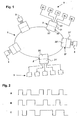
- a broadband communication network 1 with a plurality of data channels is shown schematically in FIG.
- the communication network 1 is connected to a plurality of data transmission units 2, 2 ', 2 "or access multiplexers, the data transmission units each consisting of a network-side and a user-side part.
- the network-side part 20, 20', 20" contains commercially available fast broadband transmission means.
- the data transmission unit is connected directly to the communication network.
- the data transmission unit according to the invention can also be used as a connecting device between superordinate access or transport multiplexers and user devices connected to the communication network.
- the user-side part 21, 21 ', 21 also has known, commercially available connecting means for interfacing with the user devices.
- clients or user devices 3,31,32,33,34,35 can be connected to the data transmission unit 2,2', 2" .
- Such user devices are, for example, telephone sets, computers, printers, fax machines or modems. These user devices can have various types of synchronous as well as asynchronous interfaces.
- the user-side part 21 of the first data transmission unit 2 is connected to the following user devices: the user device with the reference number 31 has an RS232 interface, the device 32 an RS422 interface, the device 33 a 485 interface, the device 34 an Ethernet interface and the device 35 is a telephone.
- Each of these user devices 31, 32, 33, 34, 35 now supplies a different user signal to the first data transmission unit 2 via an interface, the first two being asynchronous and thus not bus-capable, the others being.
- the data transmission unit 2 now has at least one Allocation means 22,23,24,25,26 to the respective interfaces of the Assign an additive neutral element to user devices 31, 32, 33, 34, 35.
- An allocation means is preferred both on the user side and on the network side available.
- the Data transmission unit 2 has an allocation means 22, 23, 24, 25, 26.
- the synchronous interfaces also have one Allocation means.
- An additive neutral element is understood to mean a digital value which, when added to another element, this other element reproduces.
- This additive neutral element which is in the communication network is sent, defines the idle state of the user device, that is, the State in which no user signals are transmitted. The additive The neutral element thus becomes a zero vector of the communication network equated.
- a synchronous interface this will preferably already be existing null element used.
- the allocation element redeems a neutral element for asynchronous interfaces electrical level of the interface from a logical level and converted the state "active" and the state "inactive” such that "inactive" one additive neutral element corresponds.
- the passive one State assigned to the logical state ONE as a neutral element.
- the RS422 interface which is between a positive and negative Voltage difference, the logical state is the neutral element Given ONE for the positive voltage difference.
- RS485 already knows three States, namely ACTIVE, INACTIVE and HIGH-OHM, the neutral element the already existing signal is therefore HIGH RESISTANCE.
- the ethernet knows also three states and is treated like RS485. Are on the phone countless states known that are digitized by scanning, so that there are 256 states. The value at which no sound is transmitted corresponds to the neutral element. Preferably all Interfaces treated uniformly, that is, the neutral elements are in identical zero vectors of the same length are flipped. Is the telephony in the Communication network is also taken into account, a vector is preferably used used, which can denote 256 states. With the RS232 Interface this is done, for example, by waiting in each case, until 8 bits have arrived.
- the communication network 1 provides data channels between data transmission units to disposal.
- data signals are sent, for example via a first Data channel 10 of the communication network 1 to the second Data transmission unit 2 ', these data signals become transparent transfer.
- FIG Reference number A denotes.
- the illustration shows a bit pattern that is sequential or transmitted or received in parallel. The remaining However, user devices are set to the zero vector, which is also constant is transmitted.
- Collisions during data transmission occur when a device which receives data over different channels with more than one channel the data is not equal to the zero vector.
- a second user device 3 is transmitting, for example a third one Data transmission unit 2 ", also data signals via a second Data channel 11, or the data signals of the user device 31 become redundant transmitted over the second data channel 11.
- Such a second data signal is designated by the reference number B in FIG.
- the second data transmission unit 2 'colliding data signals, which is in the state technology would normally cause subsequent signals to go out one data channel would overwrite the signals from the other channel. Therefore, the second data transmission unit 2 'has an addition means which adds the data signals A, B obtained from both data channels 10, 11 and provides a modulo function.
- modulo 256 is used and a limitation is made to a maximum value, to include telephony too.
- Suitable as an addition agent especially an addition circuit. This works according to A-law, for example or ⁇ -law, that is, two are coded according to A-law or ⁇ -law Signals are decoded, added, and the sum is encoded again. The through the Addition circuit obtained sum of the data signals is in Figure 2 with the Reference number C denotes. Since this signal is no longer a known one Corresponds to the transmission protocol, recognizes the second data transmission unit 2 'a data collision and can trigger appropriate actions to the involved transmitting and receiving units attentively to this collision do. This makes sense if the data channels transmit digital user data.
- the addition by the addition circuit corresponds to one Summation of the two audio signals. This is for a conference call desired so that no data collision is signaled.
- the limitation on a maximum value corresponds to a limitation to a maximum volume of the sum audio signal.
- each data transmission unit 2,2 ', 2 both transmitting data signals transmitted, as well as that they come from the Communication network received data signals to its user devices forwards. So that the data transmission units with asynchronous Participants in a data collision-proof cross-connect connection can participate, they have to add the inventive addition as well have the assignment element. However, it is possible that individual with the Access multiplexer connected to the communication network via none Assignment element. That is, if only with User devices are connected to data bus-compatible interfaces, whose Neutral elements already the zero vector of the communication network correspond.
Landscapes
- Engineering & Computer Science (AREA)
- Computer Networks & Wireless Communication (AREA)
- Time-Division Multiplex Systems (AREA)
- Data Exchanges In Wide-Area Networks (AREA)
Abstract
Description
Die Datenübertragungseinheiten sind mit Additionsschaltungen versehen, in welchen empfangene Datensignale miteinander addiert werden. Die gesendeten Neutralelemente verändern das erhaltene Benutzersignal in der Addition nicht, so dass das Benutzersignal an den Empfänger weitergeleitet werden kann. Werden jedoch zwei kollidierende Benutzersignale empfangen, so wird dies mittels der Additionsschaltung erkannt.
- Figur 1
- eine schematische Darstellung eines Kommunikationsnetzes mit mehreren Datenübertragungseinheiten und
- Figur 2
- eine schematische Darstellung von zwei gesendeten Benutzersignalen und dem empfangenen addierten Signal.
Der benutzerseitige Teil 21,21',21" weist ebenfalls bekannte, handelsübliche Verbindungsmittel zur Schnittstellenverbindung mit den Benutzergeräten auf. Benutzerseitig sind Klienten oder Benutzergeräte 3,31,32,33,34,35 an die Datenübertragungseinheit 2,2',2" anschliessbar. Derartige Benutzergeräte sind beispielsweise Telephonapparate, Computer, Drucker, Faxgeräte oder Modems. Diese Benutzergeräte können verschiedenartige, synchrone wie auch asynchrone Schnittstellen aufweisen. So ist in diesem Beispiel der benutzerseitige Teil 21 der ersten Datenübertragungseinheit 2 mit folgenden Benutzergeräten verbunden: das Benutzergerät mit der Bezugsziffer 31 weist eine RS232-Schnittstelle, das Gerät 32 eine RS422-Schnittstelle auf, das Gerät 33 eine 485-Schnittstelle, das Gerät 34 eine Ethernet-Schnittstelle und das Gerät 35 ist ein Telephon.
Jedes dieser Benutzergeräte 31,32,33,34,35 liefert nun über eine Schnittstelle ein anderes Benutzersignal an die erste Datenübertragungseinheit 2, wobei die ersten zwei asynchron und somit nicht busfähig sind, die anderen schon.
- 1
- Kommunikationsnetz
- 2
- Erste Datenübertragungseinheit
- 2'
- Zweites Datenübertragungseinheit
- 2"
- Dritte Datenübertragungseinheit
- 20
- erster netzseitiger Teil
- 20'
- zweiter netzseitiger Teil
- 20"
- dritter netzseitiger Teil
- 21
- erster benutzerseitiger Teil
- 21'
- zweiter benutzerseitiger Teil
- 21"
- dritter benutzerseitiger Teil
- 22,23,24,25,26
- Zuordnungsmittel
- 3, 31,32,33,34,35
- Benutzergeräte
- A
- Erstes Sendesignal
- B
- Zweites Sendesignal
- C
- Empfangssignal
Claims (11)
- Verfahren zur Erstellung einer digitalen synchronen Cross-Connect-Verbindung zwischen Datenübertragungseinheiten (2,2',2"), welche mit Schnittstellen von Benutzergeräten (3) verbunden sind, dadurch gekennzeichnet, dass asynchronen Schnittstellen ein additives Neutralelement zugeordnet wird und dass Datensignale, welche in einer Datenübertragungseinheit (2,2',2") über verschiedene Datenkanäle empfangen worden sind, miteinander addiert werden.
- Verfahren nach Anspruch 1, dadurch gekennzeichnet, dass die asynchronen Schnittstellen zugeordneten Neutralelemente und Neutralelemente von synchronen Schnittstellen Nullvektoren zugeordnet werden, welche alle dieselbe Länge aufweisen.
- Verfahren nach Anspruch 1, dadurch gekennzeichnet, dass die Addition auf einen Maximalwert begrenzt wird.
- Verfahren nach Anspruch 1, dadurch gekennzeichnet, dass das Neutralelement einem inaktiven Zustand des Benutzergerätes (3) zugeordnet wird.
- Verfahren nach Anspruch 1, dadurch gekennzeichnet, dass nach erfolgter Übermittlung von Daten bis zur Übermittlung erneuter Daten die Datenübertragungseinheit (2,2',2") das additive Neutralelement überträgt.
- Datenübertragungseinheit zur Erstellung einer digitalen synchronen Cross-Connect-Verbindung zwischen an ihn über Schnittstellen anschliessbaren Benutzergeräten (3) und einem mehrkanaligen Kommunikationsnetz (1), dadurch gekennzeichnet, dass die Datenübertragungseinheit (2,2',2") ein Zuordnungsmittel (22,23,24,25,26) zur Zuordnung eines additiven Neutralelementes an Schnittstellen der Benutzergeräte (3) und mindestens ein Additionsmittel zur Addition von über verschiedene Kanäle des Kommunikationsnetzes (1) empfangene Datensignale aufweist.
- Datenübertragungseinheit nach Anspruch 6, dadurch gekennzeichnet, dass allen additiven Neutralelementen Nullvektoren zugeordnet sind, welche alle dieselbe Länge aufweisen.
- Datenübertragungseinheit nach Anspruch 6, dadurch gekennzeichnet, dass das Additionsmittel Mittel zur Limitierung der addierten Datensignale aufweist.
- Datenübertragungseinheit nach Anspruch 6, dadurch gekennzeichnet, dass die Additionsschaltung eine 256-Modulofunktion aufweist.
- Datenübertragungseinheit nach Anspruch 6, dadurch gekennzeichnet, dass die Additionsschaltung eine A-law oder µ-law-Schaltung aufweist.
- Datenübertragungseinheit nach Anspruch 6, dadurch gekennzeichnet, dass das Additionsmittel und Zuordnungsmittel permanent aktiv ist.
Applications Claiming Priority (2)
| Application Number | Priority Date | Filing Date | Title |
|---|---|---|---|
| DE10065929A DE10065929A1 (de) | 2000-12-27 | 2000-12-27 | Datenübertragungseinheit zur Erstellung einer digitalen Cross-Connect-Verbindung |
| DE10065929 | 2000-12-27 |
Publications (2)
| Publication Number | Publication Date |
|---|---|
| EP1220566A2 true EP1220566A2 (de) | 2002-07-03 |
| EP1220566A3 EP1220566A3 (de) | 2006-08-23 |
Family
ID=7669545
Family Applications (1)
| Application Number | Title | Priority Date | Filing Date |
|---|---|---|---|
| EP01811106A Withdrawn EP1220566A3 (de) | 2000-12-27 | 2001-11-19 | Datenübertragungseinheit zur Erstellung einer digitalen Cross-Connect-Verbindung |
Country Status (4)
| Country | Link |
|---|---|
| US (1) | US20020114339A1 (de) |
| EP (1) | EP1220566A3 (de) |
| CA (1) | CA2365312A1 (de) |
| DE (1) | DE10065929A1 (de) |
Family Cites Families (9)
| Publication number | Priority date | Publication date | Assignee | Title |
|---|---|---|---|---|
| USRE29991E (en) * | 1975-03-14 | 1979-05-08 | Martin Marietta Corporation | Adaptable time division switch |
| DE3438340A1 (de) * | 1984-10-19 | 1986-04-24 | Standard Elektrik Lorenz Ag, 7000 Stuttgart | Anordnung zum anschliessen von endgeraeten und verfahren zum zuteilen von kanaelen an diese endgeraete |
| US4794591A (en) * | 1987-12-28 | 1988-12-27 | Gte Communication Systems Corporation | Digital voice switch for a multi-port conference circuit |
| DE3924635C2 (de) * | 1989-07-26 | 1998-11-05 | Asea Brown Boveri | Verfahren zur digitalen Datenübertragung im Vollduplex-Betrieb |
| US5235332A (en) * | 1991-12-16 | 1993-08-10 | Alcatel Network Systems, Inc. | Parallel ds3 aid/idle code generator |
| GB9127116D0 (en) * | 1991-12-20 | 1992-02-19 | Jahromi Fazlollah R | Interconnecting communications networks |
| DE19811518A1 (de) * | 1998-03-17 | 1999-09-23 | Bosch Gmbh Robert | Einrichtung zur Übertragung von Sprachsignalen und/oder Telefaxsignalen |
| US6539011B1 (en) * | 1998-06-10 | 2003-03-25 | Merlot Communications, Inc. | Method for initializing and allocating bandwidth in a permanent virtual connection for the transmission and control of audio, video, and computer data over a single network fabric |
| US6529518B1 (en) * | 1998-06-11 | 2003-03-04 | Sun Microsystems, Inc. | Method and apparatus for providing a network interface |
-
2000
- 2000-12-27 DE DE10065929A patent/DE10065929A1/de not_active Withdrawn
-
2001
- 2001-11-19 EP EP01811106A patent/EP1220566A3/de not_active Withdrawn
- 2001-12-17 CA CA002365312A patent/CA2365312A1/en not_active Abandoned
- 2001-12-20 US US10/023,061 patent/US20020114339A1/en not_active Abandoned
Also Published As
| Publication number | Publication date |
|---|---|
| CA2365312A1 (en) | 2002-06-27 |
| DE10065929A1 (de) | 2002-07-04 |
| US20020114339A1 (en) | 2002-08-22 |
| EP1220566A3 (de) | 2006-08-23 |
Similar Documents
| Publication | Publication Date | Title |
|---|---|---|
| DE69119701T2 (de) | Digitales Audio-Kommunikationssystem mit Zentral-Steuereinheit sowie Kommunikationsstelle | |
| DE2515801A1 (de) | Verfahren und schaltungsanordnungen zur zeitmultiplexen datenuebertragung | |
| DE2714368C3 (de) | Schaltungsanordnung zum Durchschalten von Datenwörtern unterschiedlicher Bitfolgefrequenz in Vielfachverbindungen | |
| DE19526484A1 (de) | Verfahren, Kommunikationssystem und Konferenzeinheit zur Durchführung von Konferenzen | |
| DE1512066A1 (de) | Zeitmultiplexvermittlungssystem | |
| DE3808413C1 (de) | ||
| DE2608575A1 (de) | Schaltungsanordnung fuer digitale sprachsignaluebertragung mit digitaler echounterdrueckung | |
| DE3438340A1 (de) | Anordnung zum anschliessen von endgeraeten und verfahren zum zuteilen von kanaelen an diese endgeraete | |
| EP0448927A1 (de) | Verfahren zum Übertragen von zeitdiskreten Informationen | |
| AT390857B (de) | Schaltungsanordnung zum vermitteln von datensignalen unterschiedlicher datensignalraten in einer datenvermittlungsanlage | |
| EP1220566A2 (de) | Datenübertragungseinheit zur Erstellung einer digitalen Cross-Connect-Verbindung | |
| DE3501674A1 (de) | Multiplexer/demultiplexer mit flexibler signalverarbeitungsfunktion fuer digitale zeitmultiplex-nachrichtenuebertragungssysteme | |
| EP0333126B1 (de) | Fernmelde-Nebenstellenanlage für Breitband-Signalübertragung | |
| DE2103307A1 (de) | Schaltungsanordnung zur Eingabe von Daten in nicht besetzte Kanäle eines Multiplexsystem | |
| DE3817407C2 (de) | ||
| DE2828602B1 (de) | Verfahren zum UEbertragen von Daten in einem synchronen Datennetz | |
| DE3045431C2 (de) | Statistisches Zeitmultiplexsystem | |
| DE2316478B2 (de) | Verfahren zur Prüfung und Aufrechterhaltung der Funktionsfähigkeit eines Zeitmultiples-Vermittlungsnetzes | |
| DE3307347C2 (de) | ||
| DE3104470C2 (de) | ||
| DE19549149A1 (de) | Verfahren zur Steuerung der Übertragung von digitalen Nachrichtensignalen über ein Zeitmultiplex-Übertragungsmedium | |
| DE29811851U1 (de) | Endgeräteadapter für bidirektionale Kabelfernsehnetze | |
| DE3343280A1 (de) | Nachrichtenvermittlungssystem | |
| DE3314596C2 (de) | Verfahren zur Einspeisung von Hörtönen und zur Realisierung von Mehrfachverbindungen in zeitmultiplex digital durchschaltenden Fernmelde-, insbesondere Fernsprechanlagen | |
| DE2930420B1 (de) | Digital-Fernmeldesystem |
Legal Events
| Date | Code | Title | Description |
|---|---|---|---|
| PUAI | Public reference made under article 153(3) epc to a published international application that has entered the european phase |
Free format text: ORIGINAL CODE: 0009012 |
|
| AK | Designated contracting states |
Kind code of ref document: A2 Designated state(s): AT BE CH CY DE DK ES FI FR GB GR IE IT LI LU MC NL PT SE TR |
|
| AX | Request for extension of the european patent |
Free format text: AL;LT;LV;MK;RO;SI |
|
| PUAL | Search report despatched |
Free format text: ORIGINAL CODE: 0009013 |
|
| AK | Designated contracting states |
Kind code of ref document: A3 Designated state(s): AT BE CH CY DE DK ES FI FR GB GR IE IT LI LU MC NL PT SE TR |
|
| AX | Request for extension of the european patent |
Extension state: AL LT LV MK RO SI |
|
| AKX | Designation fees paid | ||
| REG | Reference to a national code |
Ref country code: DE Ref legal event code: 8566 |
|
| STAA | Information on the status of an ep patent application or granted ep patent |
Free format text: STATUS: THE APPLICATION IS DEEMED TO BE WITHDRAWN |
|
| 18D | Application deemed to be withdrawn |
Effective date: 20070224 |