EP1220564A2 - Schalteinrichtung für ein optischer Übertragungsnetzwerk - Google Patents
Schalteinrichtung für ein optischer Übertragungsnetzwerk Download PDFInfo
- Publication number
- EP1220564A2 EP1220564A2 EP01130530A EP01130530A EP1220564A2 EP 1220564 A2 EP1220564 A2 EP 1220564A2 EP 01130530 A EP01130530 A EP 01130530A EP 01130530 A EP01130530 A EP 01130530A EP 1220564 A2 EP1220564 A2 EP 1220564A2
- Authority
- EP
- European Patent Office
- Prior art keywords
- channel
- switch
- fibers
- block
- channels
- Prior art date
- Legal status (The legal status is an assumption and is not a legal conclusion. Google has not performed a legal analysis and makes no representation as to the accuracy of the status listed.)
- Granted
Links
Images
Classifications
-
- H—ELECTRICITY
- H04—ELECTRIC COMMUNICATION TECHNIQUE
- H04Q—SELECTING
- H04Q11/00—Selecting arrangements for multiplex systems
- H04Q11/0001—Selecting arrangements for multiplex systems using optical switching
- H04Q11/0005—Switch and router aspects
-
- H—ELECTRICITY
- H04—ELECTRIC COMMUNICATION TECHNIQUE
- H04Q—SELECTING
- H04Q11/00—Selecting arrangements for multiplex systems
- H04Q11/0001—Selecting arrangements for multiplex systems using optical switching
- H04Q11/0005—Switch and router aspects
- H04Q2011/0007—Construction
- H04Q2011/0016—Construction using wavelength multiplexing or demultiplexing
-
- H—ELECTRICITY
- H04—ELECTRIC COMMUNICATION TECHNIQUE
- H04Q—SELECTING
- H04Q11/00—Selecting arrangements for multiplex systems
- H04Q11/0001—Selecting arrangements for multiplex systems using optical switching
- H04Q11/0005—Switch and router aspects
- H04Q2011/0007—Construction
- H04Q2011/0024—Construction using space switching
-
- H—ELECTRICITY
- H04—ELECTRIC COMMUNICATION TECHNIQUE
- H04Q—SELECTING
- H04Q11/00—Selecting arrangements for multiplex systems
- H04Q11/0001—Selecting arrangements for multiplex systems using optical switching
- H04Q11/0005—Switch and router aspects
- H04Q2011/0052—Interconnection of switches
Definitions
- the invention is based on a switching device for optical transmission network, with a first switch, to which a plurality of fibers are connected, the each with a plurality of channels different Wavelength are provided, the first switch to do so is suitable, each channel each of the fibers with each to connect another channel of all fibers.
- Such a switching device is, for example, as Digital Cross Connect Switch (DXC) at a wavelength Division Multiplex (WDM) transmission network known.
- the Switching device can there as electrical or optical Matrix switch can be realized with which each channel one any fiber with any channel of any other fiber can be connected.
- the object of the invention is to provide a switching device for to create an optical transmission network that a sensible realization of a large number of Switching connections enabled.
- This task is at the beginning of a switching device mentioned type according to the invention solved in that at least one channel of the fibers is not at the first Switch, but connected to a second switch is, the second switch is only suitable for everyone Channel of a first of the fibers with each channel of a second to connect the fibers.
- the switching device according to the invention is not more suitable that any channel of any fiber can be connected to each channel of all other fibers.
- this can easily be compensated by that with the help of a higher-level management system entire transmission network or the ones to be set up with it Connections are controlled globally.
- At least one channel of the fibers is not at the first Switch and not to the second switch, but to an amplifier connected, the amplifier only is suitable for having each channel a first of the fibers the corresponding channel of the same wavelength of a second to connect the fibers.
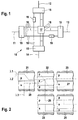
- a digital switching device 10 is shown in FIG shown, which is intended to four optical fibers 11, 12, 13, 14 to connect.
- the Switching device 10 can be as electrical or as optical switch be formed.
- the switching device 10 represents a so-called “digital cross connect switch (DXC) ".
- the fibers connected to the switching device 10 11, 12, 13, 14 can optical signals on a plurality transmitted by channels 16.
- the existing channels by their wavelength.
- this is expressed in that the fibers 11, 12, 13, 14 with the aid of multiplexing devices 15 the individual channels 16 can be divided, the channels 16 each of the fibers 11, 12, 13, 14 differ in wavelength differ.
- the fibers 11, 12, 13 include 14 to a so-called Wavelength Division Multiplex (WDM) Transmission network.
- WDM Wavelength Division Multiplex
- the switching device 10 has a first switch 17 on, with each connected input 18 with each other connected input 18 can be connected.
- the switch 17 is preferably a matrix switch educated. With the help of switch 17 anyone can incoming channel 16 on the output side as desired be forwarded. The wavelength of the forwarded channel 16 can also be changed become.
- Each channel 16 of fiber 11 connected to switch 17 can thus be connected to any channel 16 which is too one of the fibers 12, 13, 14 belongs and also with the Switch 17 is connected. This applies accordingly Manner for each of the channels 16 of the fibers 12, 13, 14.
- the channels not connected to the first switch 17 16 'of the two fibers 11 and 13 are over a second Switch 19 connected together.
- the switches 19 are preferably designed as a matrix switch. With help of the switch 19, the wavelength of an incoming Channel 16 'to a different output side Wavelength can be changed. The connection between the respective two fibers 11 and 13 or 12 and 14 remains unchanged.
- FIG. 1 Exemplary connections are shown in FIG shown schematically using a A plurality of the switching devices 10 of FIG. 1 are constructed can be.
- Each of the three columns in FIG. 2 blocks 21, 22, 23, 24, 25 shown is by means of a switching device 10 realized.
- the blocks 21, 23, 24 are divided into two areas, the are identified by the reference symbols s and p.
- the blocks 22, 25 are divided into three areas s and p divided.
- Blocks 21, 22, 23, 24, 25 represent the Fibers 11, 12, 13, 14 depending on the wavelengths of the existing channels 16.
- the areas s and p of the Blocks 21, 22, 23, 24, 25 have different ones Wavelengths.
- the area s is always about Channels 16 connected to the first switch 17 are, and which are therefore forwarded arbitrarily can.
- the area p (“pass”) is always about Channels 16 that are not connected to the first switch 17 are connected, but their wavelength by means of second switch 19 can be changed.
- the areas s and p of adjacent blocks 21, 22, 23 and 24, 25 are in terms of their wavelengths trained differently and are at least partially arranged overlapping.
- a first connection 26 is dashed in FIG. 2 shown.
- the wavelength ⁇ 1 of the channel 16 associated with this connection changed that this changed wavelength in the following block 22 one of those channels 16 is assigned, which can be switched as required.
- the Connection 26 thus belongs to the area in block 21 p, but in block 22 to area s.
- connection 26 is then changed to another Fiber switched. This follows from the fact that the Link 26 out of block 22 and into block 24 is introduced. The connection 26 belongs in block 24 again to the area s. From block 24 is the Connection 26 then in area p of block 25 forwarded.
- a second connection 27 is dotted in FIG. 2 shown. With this connection 27 the wavelength ⁇ 2 of the associated channel 16 only in block 22 changed. Then in block 23 the connection 27 is on the block 25 forwarded. Channel 16 is now included the wavelength ⁇ 2 from block 21 to block 25 advanced.
- a third connection 28 is shown in FIG. 2 shown in dash-dotted lines.
- this connection 28 the channel 16 with a wavelength ⁇ 3 in the range s of Blocks 21 initiated.
- the wavelength changed within the range s such that the channel 16 is then assigned to area p in block 23.
- Block 22 thus becomes channel 16 via the associated first Switch 17 switched on, while in block 23 the Channel 16 on the associated first switch 17 is passed.
- the switching device 10 of Figure 1 can be seen as Imagine motorway junction. There is continuous traffic that in Figure 2 by the areas p ("pass") of individual blocks is realized. There is still Turn traffic, which in Figure 2 through the areas s ("switch") of the individual blocks is realized. The through traffic can switch to turning traffic, what in Figure 2 a change in wavelength equivalent.
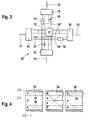
- FIG. 3 shows a switching device 30, largely the switching device 10 of FIG. 1 equivalent. Corresponding components are therefore marked with matching reference numbers.
- the switching device 30 has the Figure 3 additional channels 16 '', which neither with first switch 17, still with the second switches 19th are connected. Instead, these channels contain 16 '' no switches within the switching device 30, but only one amplifier 32 per channel.
- FIG. 4 shows exemplary connections in shown schematically using a A plurality of the switching devices 30 of FIG. 3 are constructed can be.
- the representation of Figure 4 corresponds the representation of Figure 3.
- Corresponding Functions are therefore with the same reference numbers characterized.
- Blocks 33, 34, 35 are present in FIG. How from 4 shows an additional area a ("amplify") present in blocks 33, 34, 35, the is ultimately assigned to those channels 16 ′′ that none of the switches 17 or 19, only the amplifier 32 included. As can also be seen from FIG. 4, the areas a, p and s overlap each other arranged. In particular, areas a and p alternate in successive blocks 33, 34, 35 each.
- a first connection 36 is dotted in FIG. 4 shown.
- This connection 36 identifies a channel 16, which is in block 33 in area a, in the block 34 in the area p and in the block 35 again in the Area a is located.
- This channel 16 is thus in everyone second consecutive block 33, 35 reinforced and must only a small number of switches 19 in block 34 happen.
- the channel 16 has the wavelength ⁇ 1 that can't change.
- a second connection 37 is dashed in FIG. 4 shown.
- the channel 16 of this connection 37 has the Wavelength ⁇ 2. It is located in block 33 in the area a and then changes to the area p in block 34. So that is it at junction 37 in area p of block 34 possible to change the wavelength of channel 16. This has the consequence that the channel 16 of the connection 37 in the block 35 is in the area s and thus one any forwarding to another block is possible.
- a third connection 38 is shown in FIG. 4 shown in dash-dotted lines.
- this connection 38 the channel 16 with a wavelength ⁇ 3 in the range s of Blocks 33 initiated.
- channel 16 is first of any other block has been initiated, then to the area a of Blocks 35 to be assigned.
Landscapes
- Engineering & Computer Science (AREA)
- Computer Networks & Wireless Communication (AREA)
- Optical Communication System (AREA)
- Use Of Switch Circuits For Exchanges And Methods Of Control Of Multiplex Exchanges (AREA)
Abstract
Description
- Figur 1
- zeigt ein schematisches Blockschaltbild eines ersten Ausführungsbeispiels einer erfindungsgemäßen Schalteinrichtung,
- Figur 2
- zeigt eine schematische Darstellung von Verbindungen mittels Schalteinrichtungen nach der Figur 1,
- Figur 3
- zeigt ein schematisches Blockschaltbild eines zweiten Ausführungsbeispiels einer erfindungsgemäßen Schalteinrichtung, und
- Figur 4
- zeigt eine schematische Darstellung von Verbindungen mittels Schalteinrichtungen nach der Figur 3.
Claims (3)
- Schalteinrichtung (10, 30) für ein optisches Übertragungsnetzwerk, mit einem ersten Schalter (17), an den eine Mehrzahl von Fasern (11, 12, 13, 14) angeschlossen sind, die jeweils mit einer Mehrzahl von Kanälen (16) unterschiedlicher Wellenlänge versehen sind, wobei der erste Schalter (17) dazu geeignet ist, jeden Kanal (16) jeder der Fasern (11, 12, 13, 14) mit jedem anderen Kanal (16) der Fasern (11, 12, 13, 14) zu verbinden, dadurch gekennzeichnet, daß mindestens ein Kanal (16') der Fasern (11, 12, 13, 14) nicht an den ersten Schalter (17), sondern an einen zweiten Schalter (19) angeschlossen ist, wobei der zweite Schalter (19) nur dazu geeignet ist, jeden Kanal (16') einer ersten der Fasern (11, 12, 13, 14) mit jedem Kanal (16') einer zweiten der Fasern (11, 12, 13, 14) zu verbinden.
- Schalteinrichtung (30) nach Anspruch 1, dadurch gekennzeichnet, daß mindestens ein Kanal (16'') der Fasern (11, 12, 13, 14) nicht an den ersten Schalter (17) und nicht an den zweiten Schalter (19), sondern an einen Verstärker (32) angeschlossen ist, wobei der Verstärker (32) nur dazu geeignet ist, jeden Kanal (16'') einer ersten der Fasern (11, 12, 13, 14) mit dem zugehörigen Kanal (16'') gleicher Wellenlänge einer zweiten der Fasern (11, 12, 13, 14) zu verbinden.
- Managementsystem zur Steuerung einer Mehrzahl von Schalteinrichtungen (10, 30) nach Anspruch 1 oder 2, dadurch gekennzeichnet, dass das Managementsystem beim Aufbau einer Verbindung die verschiedenen Möglichkeiten der Weiterschaltung von Kanälen (16, 16' 16'') durch die Schalteinrichtungen(10, 30) berücksichtigt.
Applications Claiming Priority (2)
| Application Number | Priority Date | Filing Date | Title |
|---|---|---|---|
| DE10065499A DE10065499A1 (de) | 2000-12-28 | 2000-12-28 | Schalteinrichtung für ein optisches Übertragungsnetzwerk |
| DE10065499 | 2000-12-28 |
Publications (3)
| Publication Number | Publication Date |
|---|---|
| EP1220564A2 true EP1220564A2 (de) | 2002-07-03 |
| EP1220564A3 EP1220564A3 (de) | 2004-01-14 |
| EP1220564B1 EP1220564B1 (de) | 2006-07-12 |
Family
ID=7669292
Family Applications (1)
| Application Number | Title | Priority Date | Filing Date |
|---|---|---|---|
| EP01130530A Expired - Lifetime EP1220564B1 (de) | 2000-12-28 | 2001-12-21 | Schalteinrichtung für ein optischer Übertragungsnetzwerk |
Country Status (4)
| Country | Link |
|---|---|
| US (1) | US6584243B2 (de) |
| EP (1) | EP1220564B1 (de) |
| AT (1) | ATE333201T1 (de) |
| DE (2) | DE10065499A1 (de) |
Families Citing this family (1)
| Publication number | Priority date | Publication date | Assignee | Title |
|---|---|---|---|---|
| US6721508B1 (en) | 1998-12-14 | 2004-04-13 | Tellabs Operations Inc. | Optical line terminal arrangement, apparatus and methods |
Family Cites Families (2)
| Publication number | Priority date | Publication date | Assignee | Title |
|---|---|---|---|---|
| JP3582030B2 (ja) * | 1995-07-05 | 2004-10-27 | 富士通株式会社 | クロスコネクト装置 |
| US6366716B1 (en) * | 2000-06-15 | 2002-04-02 | Nortel Networks Limited | Optical switching device |
-
2000
- 2000-12-28 DE DE10065499A patent/DE10065499A1/de not_active Withdrawn
-
2001
- 2001-12-19 US US10/021,354 patent/US6584243B2/en not_active Expired - Lifetime
- 2001-12-21 DE DE50110445T patent/DE50110445D1/de not_active Expired - Lifetime
- 2001-12-21 AT AT01130530T patent/ATE333201T1/de not_active IP Right Cessation
- 2001-12-21 EP EP01130530A patent/EP1220564B1/de not_active Expired - Lifetime
Also Published As
| Publication number | Publication date |
|---|---|
| EP1220564B1 (de) | 2006-07-12 |
| DE10065499A1 (de) | 2002-07-04 |
| US6584243B2 (en) | 2003-06-24 |
| US20020085792A1 (en) | 2002-07-04 |
| EP1220564A3 (de) | 2004-01-14 |
| ATE333201T1 (de) | 2006-08-15 |
| DE50110445D1 (de) | 2006-08-24 |
Similar Documents
| Publication | Publication Date | Title |
|---|---|---|
| EP0461519A2 (de) | Optisches Schaltelement | |
| DE69838354T2 (de) | Optischer Schalter | |
| DE69736099T2 (de) | Vorrichtung zum Ein-und Ausfügen von Wellenlängenmultiplexkanälen | |
| DE3916720A1 (de) | Verfahren zur erweiterung eines dreistufigen regelmaessigen koppelfeldes | |
| DE10213133A1 (de) | Optische Schaltstation | |
| EP1821438B1 (de) | Optische Schaltung zur Realisierung eines Knotens höherer Ordnung in einem optischen Übertragungsnetzwerk | |
| DE69534560T2 (de) | Optische Rangierverteiler | |
| DE69528951T2 (de) | Photonische Schaltmatrix | |
| DE2713610A1 (de) | Pcm-zeitmultiplexkoppelfeld | |
| DE10036709B4 (de) | Optischer Netzknoten mit Add-Drop- oder Cross-Connect-Funktionalität und dazugehörige Verfahren | |
| EP1220564B1 (de) | Schalteinrichtung für ein optischer Übertragungsnetzwerk | |
| DE10343615A1 (de) | Netzknoten für ein optisches Nachrichtenübertragungsnetz | |
| DE1512947C3 (de) | Schaltungsanordnung für Fernmeldevermittlungsanlagen mit mehrstufigen Koppelfeldern, insbesondere für Fernsprechanlagen Siemens AG, 1000 Berlin und 8000 München | |
| DE19847410A1 (de) | Optisches unidirektionales Ringnetz | |
| EP1176764B1 (de) | Verfahren zum Betreiben eines Datenübertragungsnetzwerks | |
| DE2127711C3 (de) | Schaltungsanordnung zur Erweiterung der Zu- und Abgänge zweier hintereinander angeordneter Koppelstufen einer in Fernmeldevermittlungsanlagen eingesetzten Koppelanordnung | |
| DE102006033463A1 (de) | Eindimensionaler wellenlängen-selektiver Schalter und Verfahren zum kanalweisen Schalten für einen eindimensionalen wellenlängen-selektiven Schalter | |
| DE4317856A1 (de) | Auswahlschaltung | |
| DE3819587C1 (de) | ||
| DE4203176C2 (de) | Kanalauswahlschaltung | |
| DE19859832A1 (de) | Schaltmatrix für Telekommunikationsanwendungen | |
| DE4213095A1 (de) | Optisches Schaltnetzwerk | |
| DE3151093C2 (de) | Gruppe von Lichtschaltern für ein Vermittlungssystem | |
| DE2602129C3 (de) | Schaltungsanordnung fur Fernmelde· vermlttlungsanlagen, insbesondere Fernsprechvermittlungsanlagen mit mehrstufigen Koppelfeldern | |
| DE3816948C2 (de) |
Legal Events
| Date | Code | Title | Description |
|---|---|---|---|
| PUAI | Public reference made under article 153(3) epc to a published international application that has entered the european phase |
Free format text: ORIGINAL CODE: 0009012 |
|
| AK | Designated contracting states |
Kind code of ref document: A2 Designated state(s): AT BE CH CY DE DK ES FI FR GB GR IE IT LI LU MC NL PT SE TR |
|
| AX | Request for extension of the european patent |
Free format text: AL;LT;LV;MK;RO;SI |
|
| PUAL | Search report despatched |
Free format text: ORIGINAL CODE: 0009013 |
|
| AK | Designated contracting states |
Kind code of ref document: A3 Designated state(s): AT BE CH CY DE DK ES FI FR GB GR IE IT LI LU MC NL PT SE TR |
|
| AX | Request for extension of the european patent |
Extension state: AL LT LV MK RO SI |
|
| 17P | Request for examination filed |
Effective date: 20040604 |
|
| AKX | Designation fees paid |
Designated state(s): AT BE CH CY DE DK ES FI FR GB GR IE IT LI LU MC NL PT SE TR |
|
| GRAP | Despatch of communication of intention to grant a patent |
Free format text: ORIGINAL CODE: EPIDOSNIGR1 |
|
| GRAS | Grant fee paid |
Free format text: ORIGINAL CODE: EPIDOSNIGR3 |
|
| GRAA | (expected) grant |
Free format text: ORIGINAL CODE: 0009210 |
|
| AK | Designated contracting states |
Kind code of ref document: B1 Designated state(s): AT BE CH CY DE DK ES FI FR GB GR IE IT LI LU MC NL PT SE TR |
|
| PG25 | Lapsed in a contracting state [announced via postgrant information from national office to epo] |
Ref country code: IE Free format text: LAPSE BECAUSE OF FAILURE TO SUBMIT A TRANSLATION OF THE DESCRIPTION OR TO PAY THE FEE WITHIN THE PRESCRIBED TIME-LIMIT Effective date: 20060712 Ref country code: FI Free format text: LAPSE BECAUSE OF FAILURE TO SUBMIT A TRANSLATION OF THE DESCRIPTION OR TO PAY THE FEE WITHIN THE PRESCRIBED TIME-LIMIT Effective date: 20060712 Ref country code: NL Free format text: LAPSE BECAUSE OF FAILURE TO SUBMIT A TRANSLATION OF THE DESCRIPTION OR TO PAY THE FEE WITHIN THE PRESCRIBED TIME-LIMIT Effective date: 20060712 |
|
| REG | Reference to a national code |
Ref country code: GB Ref legal event code: FG4D Free format text: NOT ENGLISH |
|
| REG | Reference to a national code |
Ref country code: CH Ref legal event code: EP |
|
| GBT | Gb: translation of ep patent filed (gb section 77(6)(a)/1977) |
Effective date: 20060725 |
|
| REG | Reference to a national code |
Ref country code: IE Ref legal event code: FG4D Free format text: LANGUAGE OF EP DOCUMENT: GERMAN |
|
| REF | Corresponds to: |
Ref document number: 50110445 Country of ref document: DE Date of ref document: 20060824 Kind code of ref document: P |
|
| PG25 | Lapsed in a contracting state [announced via postgrant information from national office to epo] |
Ref country code: SE Free format text: LAPSE BECAUSE OF FAILURE TO SUBMIT A TRANSLATION OF THE DESCRIPTION OR TO PAY THE FEE WITHIN THE PRESCRIBED TIME-LIMIT Effective date: 20061012 Ref country code: DK Free format text: LAPSE BECAUSE OF FAILURE TO SUBMIT A TRANSLATION OF THE DESCRIPTION OR TO PAY THE FEE WITHIN THE PRESCRIBED TIME-LIMIT Effective date: 20061012 |
|
| PG25 | Lapsed in a contracting state [announced via postgrant information from national office to epo] |
Ref country code: ES Free format text: LAPSE BECAUSE OF FAILURE TO SUBMIT A TRANSLATION OF THE DESCRIPTION OR TO PAY THE FEE WITHIN THE PRESCRIBED TIME-LIMIT Effective date: 20061023 |
|
| PG25 | Lapsed in a contracting state [announced via postgrant information from national office to epo] |
Ref country code: PT Free format text: LAPSE BECAUSE OF FAILURE TO SUBMIT A TRANSLATION OF THE DESCRIPTION OR TO PAY THE FEE WITHIN THE PRESCRIBED TIME-LIMIT Effective date: 20061212 |
|
| ET | Fr: translation filed | ||
| PG25 | Lapsed in a contracting state [announced via postgrant information from national office to epo] |
Ref country code: MC Free format text: LAPSE BECAUSE OF NON-PAYMENT OF DUE FEES Effective date: 20061231 Ref country code: LI Free format text: LAPSE BECAUSE OF NON-PAYMENT OF DUE FEES Effective date: 20061231 Ref country code: CH Free format text: LAPSE BECAUSE OF NON-PAYMENT OF DUE FEES Effective date: 20061231 Ref country code: BE Free format text: LAPSE BECAUSE OF NON-PAYMENT OF DUE FEES Effective date: 20061231 |
|
| NLV1 | Nl: lapsed or annulled due to failure to fulfill the requirements of art. 29p and 29m of the patents act | ||
| REG | Reference to a national code |
Ref country code: IE Ref legal event code: FD4D |
|
| RAP2 | Party data changed (patent owner data changed or rights of a patent transferred) |
Owner name: ALCATEL LUCENT |
|
| PLBE | No opposition filed within time limit |
Free format text: ORIGINAL CODE: 0009261 |
|
| STAA | Information on the status of an ep patent application or granted ep patent |
Free format text: STATUS: NO OPPOSITION FILED WITHIN TIME LIMIT |
|
| 26N | No opposition filed |
Effective date: 20070413 |
|
| REG | Reference to a national code |
Ref country code: CH Ref legal event code: PL |
|
| BERE | Be: lapsed |
Owner name: ALCATEL Effective date: 20061231 |
|
| PG25 | Lapsed in a contracting state [announced via postgrant information from national office to epo] |
Ref country code: AT Free format text: LAPSE BECAUSE OF NON-PAYMENT OF DUE FEES Effective date: 20061221 |
|
| PG25 | Lapsed in a contracting state [announced via postgrant information from national office to epo] |
Ref country code: GR Free format text: LAPSE BECAUSE OF FAILURE TO SUBMIT A TRANSLATION OF THE DESCRIPTION OR TO PAY THE FEE WITHIN THE PRESCRIBED TIME-LIMIT Effective date: 20061013 |
|
| PG25 | Lapsed in a contracting state [announced via postgrant information from national office to epo] |
Ref country code: LU Free format text: LAPSE BECAUSE OF NON-PAYMENT OF DUE FEES Effective date: 20061221 Ref country code: TR Free format text: LAPSE BECAUSE OF FAILURE TO SUBMIT A TRANSLATION OF THE DESCRIPTION OR TO PAY THE FEE WITHIN THE PRESCRIBED TIME-LIMIT Effective date: 20060712 |
|
| PG25 | Lapsed in a contracting state [announced via postgrant information from national office to epo] |
Ref country code: CY Free format text: LAPSE BECAUSE OF FAILURE TO SUBMIT A TRANSLATION OF THE DESCRIPTION OR TO PAY THE FEE WITHIN THE PRESCRIBED TIME-LIMIT Effective date: 20060712 |
|
| REG | Reference to a national code |
Ref country code: FR Ref legal event code: GC Effective date: 20140717 |
|
| REG | Reference to a national code |
Ref country code: FR Ref legal event code: RG Effective date: 20141016 |
|
| REG | Reference to a national code |
Ref country code: FR Ref legal event code: CA Effective date: 20150521 |
|
| REG | Reference to a national code |
Ref country code: FR Ref legal event code: CA Effective date: 20150521 |
|
| REG | Reference to a national code |
Ref country code: FR Ref legal event code: PLFP Year of fee payment: 15 |
|
| REG | Reference to a national code |
Ref country code: FR Ref legal event code: PLFP Year of fee payment: 16 |
|
| PGFP | Annual fee paid to national office [announced via postgrant information from national office to epo] |
Ref country code: FR Payment date: 20161222 Year of fee payment: 16 |
|
| PGFP | Annual fee paid to national office [announced via postgrant information from national office to epo] |
Ref country code: IT Payment date: 20161223 Year of fee payment: 16 |
|
| REG | Reference to a national code |
Ref country code: FR Ref legal event code: ST Effective date: 20180831 |
|
| PG25 | Lapsed in a contracting state [announced via postgrant information from national office to epo] |
Ref country code: IT Free format text: LAPSE BECAUSE OF NON-PAYMENT OF DUE FEES Effective date: 20171221 Ref country code: FR Free format text: LAPSE BECAUSE OF NON-PAYMENT OF DUE FEES Effective date: 20180102 |
|
| REG | Reference to a national code |
Ref country code: DE Ref legal event code: R082 Ref document number: 50110445 Country of ref document: DE Representative=s name: MENZIETTI WETZEL, DE Ref country code: DE Ref legal event code: R081 Ref document number: 50110445 Country of ref document: DE Owner name: PROVENANCE ASSET GROUP LLC, PITTSFORD, US Free format text: FORMER OWNER: ALCATEL LUCENT, PARIS, FR |
|
| REG | Reference to a national code |
Ref country code: GB Ref legal event code: 732E Free format text: REGISTERED BETWEEN 20190829 AND 20190904 |
|
| PGFP | Annual fee paid to national office [announced via postgrant information from national office to epo] |
Ref country code: GB Payment date: 20201029 Year of fee payment: 20 Ref country code: DE Payment date: 20201027 Year of fee payment: 20 |
|
| REG | Reference to a national code |
Ref country code: DE Ref legal event code: R071 Ref document number: 50110445 Country of ref document: DE |
|
| REG | Reference to a national code |
Ref country code: GB Ref legal event code: PE20 Expiry date: 20211220 |
|
| PG25 | Lapsed in a contracting state [announced via postgrant information from national office to epo] |
Ref country code: GB Free format text: LAPSE BECAUSE OF EXPIRATION OF PROTECTION Effective date: 20211220 |