EP1220401A2 - Gehäuse aus Kunststoff - Google Patents
Gehäuse aus Kunststoff Download PDFInfo
- Publication number
- EP1220401A2 EP1220401A2 EP01403268A EP01403268A EP1220401A2 EP 1220401 A2 EP1220401 A2 EP 1220401A2 EP 01403268 A EP01403268 A EP 01403268A EP 01403268 A EP01403268 A EP 01403268A EP 1220401 A2 EP1220401 A2 EP 1220401A2
- Authority
- EP
- European Patent Office
- Prior art keywords
- shell
- shells
- projection
- attached
- housing
- Prior art date
- Legal status (The legal status is an assumption and is not a legal conclusion. Google has not performed a legal analysis and makes no representation as to the accuracy of the status listed.)
- Granted
Links
Images

Classifications
-
- B—PERFORMING OPERATIONS; TRANSPORTING
- B60—VEHICLES IN GENERAL
- B60R—VEHICLES, VEHICLE FITTINGS, OR VEHICLE PARTS, NOT OTHERWISE PROVIDED FOR
- B60R16/00—Electric or fluid circuits specially adapted for vehicles and not otherwise provided for; Arrangement of elements of electric or fluid circuits specially adapted for vehicles and not otherwise provided for
- B60R16/02—Electric or fluid circuits specially adapted for vehicles and not otherwise provided for; Arrangement of elements of electric or fluid circuits specially adapted for vehicles and not otherwise provided for electric constitutive elements
- B60R16/0207—Wire harnesses
- B60R16/0215—Protecting, fastening and routing means therefor
- B60R16/0222—Grommets
Definitions
- the invention relates to a housing made of plastic for receiving lines, consisting of two half-shells that can be released by at least two snap-in elements can be connected to one another, in which the latching elements each consist of one attached to a first half-shell, protruding outwards and from a corresponding one attached to the outside of the second half shell frame-like closing part exist, its a boundary of the half-shell itself is formed and which engages around the projection of the first half-shell in the assembly position.
- Such housings have been known for years for a wide variety of applications available on the market. They are in the embodiment described above used, for example, to protect and guide electrical cables in places, where the lines would otherwise be exposed and easily damaged mechanically could become.
- a possible area of application is, for example, motor vehicles at which electrical lines are laid in the body and also in the interior, for example in the seats.
- the housings can be straight or curved his.
- the half-shells of the housing are in the embodiment described above easy to put together thanks to the snap-in elements. There will be none Tools and no additional fasteners needed. If the locking parts of the one half-shell the projections of the other half-shell in the assembly position reach around, the housing is closed. When joining the two half shells However, the same must be positioned exactly so that the locking parts can actually be pressed over the corresponding projections.
- the invention has for its object to the housing described above shape that its assembly can be further simplified.
- This object is achieved according to the invention in that on each of the locking parts two spaced parallel to each other, in the direction of when joining guide arms pointing to the movement to be performed are attached, whose distance from each other corresponds to the width of a projection.
- the "finding" of the projections by the guide arms can then be further facilitated when the free ends thereof are tapered.
- the slope of the The taper points away from the associated half-shell.
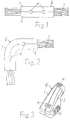
- Fig. 1 is a rectilinear housing G consisting of two half-shells 1 and 2 shown. It is used to hold, guide and protect electrical Lines 3.
- the housing G is made of plastic, for example of polypropylene. Its two half-shells 1 and 2 are connected to one another by snap-in elements 4 connected, two of which are shown schematically in FIG. 1.
- the housing G can be tubular, so that the half-shells 1 and 2 one have approximately semicircular cross-section. But it is also any other meaningful one Cross-sectional shape can be used for the housing G.
- the housing G can also Fastening elements can be attached, by means of which the same is fastened to a carrier can be.
- the housing G shown in Fig. 3 is with locking elements 5 as Fasteners equipped.
- the resiliently engaging elements 4 of the housing G are shown in FIGS. 3 to 6 as Embodiment in enlarged representations. There are at least two such elements 4 attached to the housing G.
- half shell 2 On the half shell 2 is part of a resiliently engaging element 4 to the outside protruding projection 6 attached. It is advantageous on one side edge of the Half-shell 2 positioned. The front, starting from the side edge of the half-shell 2 Edge 7 of the projection 6 runs obliquely away from the side edge, while the rear Edge 8 protrudes from half-shell 2 at right angles.
- a frame-like locking part 9 attached, which in the mounting position - so at closed housing G - engages around the projection 6 of the half-shell 2, as in Fig. 6 is shown.
- the closing part 9 consists of two strips 10 attached to the outside of the half-shell 1 and 11, which are parallel to each other at a distance and in the direction of the Closing the housing G given direction of movement over the side edge of the Project half shell 1. They are at a distance from the half-shell 1 by a web 12 connected with each other.
- the closing part 9 thus encloses as a frame-like component a here rectangular or square free space 13 on one side of the Side edge of the half-shell 1 itself is limited. Raises into the free space 13 Mounting position of the housing G of the projection 6 of the half-shell 2.
- the web 12 then lies behind the edge 8 of the projection 6.
- Guide arms 14 and 15 are located on the closing part 9 at a distance and parallel to one another attached, in the given direction of movement when closing the housing G. protrude beyond the closing part 9. They have a width of the projection 6 corresponding distance from each other and are in the illustrated embodiment Extensions of the strips 10 and 11.
- the guide arms 14 and 15 are used for simplified assembly of the housing G. You capture when assembling the two half-shells 1 and 2 the respective projection 6 of the half-shell 2 before the actual closing process. If the projection 6 between the guide arms 14 and 15 lies, the half-shells 1 and 2 have their correct position to each other. she then just need to be squeezed together. A sideways evasion is not possible. When the two half-shells 1 and 2 are pressed together, the web becomes 12 of the closing part 9 pressed upwards by the oblique edge 7 of the projection 6. He then snaps behind the projection 6.
- the "finding" of the projections 6 can be made easier by the fact that the free Ends of the guide arms 14 and 15 are tapered, with one of the associated half-shell technological slope.
- Projection 6 and associated free space 13 are in the exemplary embodiment described shown rectangular. You can also have another meaningful geometric shape.
- the projections 6 can also be attached to the half-shell 1, so that the Locking parts 9 are then located on the half-shells 2. It is also possible each time correspondingly, both projections 6 and locking parts 9 on both half-shells 1 and 2 attach.
Landscapes
- Engineering & Computer Science (AREA)
- Mechanical Engineering (AREA)
- Casings For Electric Apparatus (AREA)
- Magnetically Actuated Valves (AREA)
- Diaphragms For Electromechanical Transducers (AREA)
- Installation Of Indoor Wiring (AREA)
- Details Of Connecting Devices For Male And Female Coupling (AREA)
- Position Input By Displaying (AREA)
- Telephone Set Structure (AREA)
- Clamps And Clips (AREA)
Abstract
Description
Claims (2)
- Gehäuse aus Kunststoff zur Aufnahme von Leitungen, bestehend aus zwei Halbschalen, die durch mindestens zwei einrastende Elemente lösbar miteinander verbindbar sind, bei welchem die einrastenden Elemente jeweils aus einem an einer ersten Halbschale angebrachten, nach außen abstehenden Vorsprung sowie aus einem korrespondierenden, an der zweiten Halbschale außen angebrachten rahmenartigen Schließteil bestehen, dessen eine Begrenzung von der Halbschale selbst gebildet ist und der in Montageposition den Vorsprung der ersten Halbschale umgreift, dadurch gekennzeichnet, daß an jedem der Schließteile (9) zwei mit Abstand parallel zueinander verlaufende, in Richtung der beim Zusammenfügen der Halbschalen (1,2) durchzuführenden Bewegung weisende Führungsarme (14,15) angebracht sind, deren Abstand voneinander der Breite eines Vorsprungs (6) entspricht.
- Gehäuse nach Anspruch 1, dadurch gekennzeichnet, daß die freien Enden der Führungsarme (14,15) konisch verjüngt sind, mit von der zugehörigen Halbschale wegweisender Schräge.
Applications Claiming Priority (2)
| Application Number | Priority Date | Filing Date | Title |
|---|---|---|---|
| DE20021572U DE20021572U1 (de) | 2000-12-21 | 2000-12-21 | Gehäuse aus Kunststoff |
| DE20021572U | 2000-12-21 |
Publications (3)
| Publication Number | Publication Date |
|---|---|
| EP1220401A2 true EP1220401A2 (de) | 2002-07-03 |
| EP1220401A3 EP1220401A3 (de) | 2003-05-21 |
| EP1220401B1 EP1220401B1 (de) | 2005-10-26 |
Family
ID=7950336
Family Applications (1)
| Application Number | Title | Priority Date | Filing Date |
|---|---|---|---|
| EP01403268A Expired - Lifetime EP1220401B1 (de) | 2000-12-21 | 2001-12-14 | Gehäuse aus Kunststoff |
Country Status (4)
| Country | Link |
|---|---|
| EP (1) | EP1220401B1 (de) |
| AT (1) | ATE308139T1 (de) |
| DE (2) | DE20021572U1 (de) |
| ES (1) | ES2248256T3 (de) |
Family Cites Families (2)
| Publication number | Priority date | Publication date | Assignee | Title |
|---|---|---|---|---|
| JP2758109B2 (ja) * | 1992-08-31 | 1998-05-28 | 矢崎総業株式会社 | ロック構造 |
| JP3427949B2 (ja) * | 1994-07-19 | 2003-07-22 | 住友電装株式会社 | グロメット |
-
2000
- 2000-12-21 DE DE20021572U patent/DE20021572U1/de not_active Expired - Lifetime
-
2001
- 2001-12-14 ES ES01403268T patent/ES2248256T3/es not_active Expired - Lifetime
- 2001-12-14 DE DE50107819T patent/DE50107819D1/de not_active Expired - Lifetime
- 2001-12-14 AT AT01403268T patent/ATE308139T1/de active
- 2001-12-14 EP EP01403268A patent/EP1220401B1/de not_active Expired - Lifetime
Also Published As
| Publication number | Publication date |
|---|---|
| EP1220401B1 (de) | 2005-10-26 |
| EP1220401A3 (de) | 2003-05-21 |
| ES2248256T3 (es) | 2006-03-16 |
| ATE308139T1 (de) | 2005-11-15 |
| DE50107819D1 (de) | 2005-12-01 |
| DE20021572U1 (de) | 2001-02-22 |
Similar Documents
| Publication | Publication Date | Title |
|---|---|---|
| DE202014011217U1 (de) | Halterahmen für einen Steckverbinder | |
| WO2015085994A1 (de) | Halterahmen für einen steckverbinder | |
| DE102019135726A1 (de) | Halterahmen für einen Steckverbinder | |
| EP0875084B1 (de) | Vorrichtung zum elektrisch leitenden verbinden des rahmengestells oder des schrankkorpus eines schaltschrankes mit der türe | |
| DE3744644A1 (de) | Vorrichtung zum befestigen einer luefterhaube am wasserkasten eines luft/wasser-kuehlers fuer kraftfahrzeuge | |
| DE2511385C3 (de) | Elektrische Anschlußklemme | |
| DE602005004108T2 (de) | Vielfacher Gerätehalter zur horizontalen und vertikalen Montage. | |
| DE29509360U1 (de) | Vorrichtung zum Befestigen eines mit einem plattenförmigen Teil versehenen Elementes an einer Wand in einem Gehäuse o.dgl. | |
| DE102013113974A1 (de) | Halterahmen für einen Steckverbinder | |
| EP0749180B1 (de) | Steckverbindergehäuse | |
| EP1220401B1 (de) | Gehäuse aus Kunststoff | |
| DE10004220C2 (de) | Vorrichtung zur Klemmbefestigung einer Flachbatterie | |
| DE102018133135A1 (de) | Halterahmen für einen Steckverbinder | |
| EP0722208A2 (de) | Anordnung zur Einbauhalterung von Elektro-Installationsgeräten | |
| DE29616933U1 (de) | Rastvorrichtung für ein geradlinig verschiebbares Bauteil | |
| DE102013113973B4 (de) | Metallischer Halterahmen für einen Steckverbinder sowie Verfahren zur Herstellung | |
| DE202010013994U1 (de) | Quaderförmiges Gehäuse | |
| DE102007024374A1 (de) | Befestigung der Griffschalen eines Messers | |
| DE29502779U1 (de) | Potentialverteilungsvorrichtung für elektrische Anlagen | |
| EP2645501B2 (de) | Systemanordnung aus einem Systemträger und mehreren Systemmodulen für die Gebäudeelektroinstallationstechnik und Türkommunikationstechnik | |
| DE3200729C2 (de) | Einrichtung zur Befestigung von Leiterplatten in einem Trägerrahmen | |
| EP0984120A1 (de) | Verbindungsanordnung | |
| EP0903063A1 (de) | Gehäuse | |
| DE102023107157A1 (de) | Halterahmen für einen Steckverbinder | |
| EP1376801A1 (de) | Elektrisches Installationsgerät mit Tragrahmen und mindestens einem an diesem befestigten Einsatz |
Legal Events
| Date | Code | Title | Description |
|---|---|---|---|
| PUAI | Public reference made under article 153(3) epc to a published international application that has entered the european phase |
Free format text: ORIGINAL CODE: 0009012 |
|
| AK | Designated contracting states |
Kind code of ref document: A2 Designated state(s): AT BE CH CY DE DK ES FI FR GB GR IE IT LI LU MC NL PT SE TR |
|
| AX | Request for extension of the european patent |
Free format text: AL;LT;LV;MK;RO;SI |
|
| PUAL | Search report despatched |
Free format text: ORIGINAL CODE: 0009013 |
|
| RIC1 | Information provided on ipc code assigned before grant |
Ipc: 7B 60R 16/02 B Ipc: 7H 02G 3/06 A Ipc: 7B 65D 43/00 B |
|
| AK | Designated contracting states |
Designated state(s): AT BE CH CY DE DK ES FI FR GB GR IE IT LI LU MC NL PT SE TR |
|
| AX | Request for extension of the european patent |
Extension state: AL LT LV MK RO SI |
|
| 17P | Request for examination filed |
Effective date: 20030409 |
|
| AKX | Designation fees paid |
Designated state(s): AT BE CH CY DE DK ES FI FR GB GR IE IT LI LU MC NL PT SE TR |
|
| GRAP | Despatch of communication of intention to grant a patent |
Free format text: ORIGINAL CODE: EPIDOSNIGR1 |
|
| GRAP | Despatch of communication of intention to grant a patent |
Free format text: ORIGINAL CODE: EPIDOSNIGR1 |
|
| GRAS | Grant fee paid |
Free format text: ORIGINAL CODE: EPIDOSNIGR3 |
|
| GRAA | (expected) grant |
Free format text: ORIGINAL CODE: 0009210 |
|
| AK | Designated contracting states |
Kind code of ref document: B1 Designated state(s): AT BE CH CY DE DK ES FI FR GB GR IE IT LI LU MC NL PT SE TR |
|
| PG25 | Lapsed in a contracting state [announced via postgrant information from national office to epo] |
Ref country code: FI Free format text: LAPSE BECAUSE OF FAILURE TO SUBMIT A TRANSLATION OF THE DESCRIPTION OR TO PAY THE FEE WITHIN THE PRESCRIBED TIME-LIMIT Effective date: 20051026 Ref country code: IE Free format text: LAPSE BECAUSE OF FAILURE TO SUBMIT A TRANSLATION OF THE DESCRIPTION OR TO PAY THE FEE WITHIN THE PRESCRIBED TIME-LIMIT Effective date: 20051026 Ref country code: TR Free format text: LAPSE BECAUSE OF FAILURE TO SUBMIT A TRANSLATION OF THE DESCRIPTION OR TO PAY THE FEE WITHIN THE PRESCRIBED TIME-LIMIT Effective date: 20051026 Ref country code: NL Free format text: LAPSE BECAUSE OF FAILURE TO SUBMIT A TRANSLATION OF THE DESCRIPTION OR TO PAY THE FEE WITHIN THE PRESCRIBED TIME-LIMIT Effective date: 20051026 |
|
| REG | Reference to a national code |
Ref country code: GB Ref legal event code: FG4D Free format text: NOT ENGLISH |
|
| REG | Reference to a national code |
Ref country code: CH Ref legal event code: EP |
|
| GBT | Gb: translation of ep patent filed (gb section 77(6)(a)/1977) |
Effective date: 20051026 |
|
| REG | Reference to a national code |
Ref country code: IE Ref legal event code: FG4D Free format text: LANGUAGE OF EP DOCUMENT: GERMAN |
|
| REF | Corresponds to: |
Ref document number: 50107819 Country of ref document: DE Date of ref document: 20051201 Kind code of ref document: P |
|
| PG25 | Lapsed in a contracting state [announced via postgrant information from national office to epo] |
Ref country code: CY Free format text: LAPSE BECAUSE OF FAILURE TO SUBMIT A TRANSLATION OF THE DESCRIPTION OR TO PAY THE FEE WITHIN THE PRESCRIBED TIME-LIMIT Effective date: 20051214 |
|
| PG25 | Lapsed in a contracting state [announced via postgrant information from national office to epo] |
Ref country code: MC Free format text: LAPSE BECAUSE OF NON-PAYMENT OF DUE FEES Effective date: 20051231 Ref country code: CH Free format text: LAPSE BECAUSE OF NON-PAYMENT OF DUE FEES Effective date: 20051231 Ref country code: LI Free format text: LAPSE BECAUSE OF NON-PAYMENT OF DUE FEES Effective date: 20051231 Ref country code: BE Free format text: LAPSE BECAUSE OF NON-PAYMENT OF DUE FEES Effective date: 20051231 Ref country code: LU Free format text: LAPSE BECAUSE OF NON-PAYMENT OF DUE FEES Effective date: 20051231 |
|
| PG25 | Lapsed in a contracting state [announced via postgrant information from national office to epo] |
Ref country code: DK Free format text: LAPSE BECAUSE OF FAILURE TO SUBMIT A TRANSLATION OF THE DESCRIPTION OR TO PAY THE FEE WITHIN THE PRESCRIBED TIME-LIMIT Effective date: 20060126 Ref country code: GR Free format text: LAPSE BECAUSE OF FAILURE TO SUBMIT A TRANSLATION OF THE DESCRIPTION OR TO PAY THE FEE WITHIN THE PRESCRIBED TIME-LIMIT Effective date: 20060126 |
|
| REG | Reference to a national code |
Ref country code: SE Ref legal event code: TRGR |
|
| REG | Reference to a national code |
Ref country code: ES Ref legal event code: FG2A Ref document number: 2248256 Country of ref document: ES Kind code of ref document: T3 |
|
| NLV1 | Nl: lapsed or annulled due to failure to fulfill the requirements of art. 29p and 29m of the patents act | ||
| REG | Reference to a national code |
Ref country code: IE Ref legal event code: FD4D |
|
| ET | Fr: translation filed | ||
| REG | Reference to a national code |
Ref country code: CH Ref legal event code: PL |
|
| PLBE | No opposition filed within time limit |
Free format text: ORIGINAL CODE: 0009261 |
|
| STAA | Information on the status of an ep patent application or granted ep patent |
Free format text: STATUS: NO OPPOSITION FILED WITHIN TIME LIMIT |
|
| 26N | No opposition filed |
Effective date: 20060727 |
|
| BERE | Be: lapsed |
Owner name: NEXANS Effective date: 20051231 |
|
| PGFP | Annual fee paid to national office [announced via postgrant information from national office to epo] |
Ref country code: ES Payment date: 20091222 Year of fee payment: 9 Ref country code: SE Payment date: 20091214 Year of fee payment: 9 |
|
| PGFP | Annual fee paid to national office [announced via postgrant information from national office to epo] |
Ref country code: PT Payment date: 20091204 Year of fee payment: 9 |
|
| REG | Reference to a national code |
Ref country code: PT Ref legal event code: MM4A Free format text: LAPSE DUE TO NON-PAYMENT OF FEES Effective date: 20110614 |
|
| PG25 | Lapsed in a contracting state [announced via postgrant information from national office to epo] |
Ref country code: PT Free format text: LAPSE BECAUSE OF NON-PAYMENT OF DUE FEES Effective date: 20110614 |
|
| REG | Reference to a national code |
Ref country code: SE Ref legal event code: EUG |
|
| PG25 | Lapsed in a contracting state [announced via postgrant information from national office to epo] |
Ref country code: SE Free format text: LAPSE BECAUSE OF NON-PAYMENT OF DUE FEES Effective date: 20101215 |
|
| REG | Reference to a national code |
Ref country code: ES Ref legal event code: FD2A Effective date: 20120220 |
|
| PG25 | Lapsed in a contracting state [announced via postgrant information from national office to epo] |
Ref country code: ES Free format text: LAPSE BECAUSE OF NON-PAYMENT OF DUE FEES Effective date: 20101215 |
|
| PGFP | Annual fee paid to national office [announced via postgrant information from national office to epo] |
Ref country code: IT Payment date: 20121221 Year of fee payment: 12 |
|
| PGFP | Annual fee paid to national office [announced via postgrant information from national office to epo] |
Ref country code: FR Payment date: 20130130 Year of fee payment: 12 |
|
| PGFP | Annual fee paid to national office [announced via postgrant information from national office to epo] |
Ref country code: GB Payment date: 20131219 Year of fee payment: 13 |
|
| REG | Reference to a national code |
Ref country code: FR Ref legal event code: ST Effective date: 20140829 |
|
| PG25 | Lapsed in a contracting state [announced via postgrant information from national office to epo] |
Ref country code: FR Free format text: LAPSE BECAUSE OF NON-PAYMENT OF DUE FEES Effective date: 20131231 |
|
| GBPC | Gb: european patent ceased through non-payment of renewal fee |
Effective date: 20141214 |
|
| PG25 | Lapsed in a contracting state [announced via postgrant information from national office to epo] |
Ref country code: IT Free format text: LAPSE BECAUSE OF NON-PAYMENT OF DUE FEES Effective date: 20131231 |
|
| PG25 | Lapsed in a contracting state [announced via postgrant information from national office to epo] |
Ref country code: GB Free format text: LAPSE BECAUSE OF NON-PAYMENT OF DUE FEES Effective date: 20141214 |
|
| PG25 | Lapsed in a contracting state [announced via postgrant information from national office to epo] |
Ref country code: IT Free format text: LAPSE BECAUSE OF NON-PAYMENT OF DUE FEES Effective date: 20131214 |
|
| PGFP | Annual fee paid to national office [announced via postgrant information from national office to epo] |
Ref country code: DE Payment date: 20171211 Year of fee payment: 17 |
|
| PGFP | Annual fee paid to national office [announced via postgrant information from national office to epo] |
Ref country code: AT Payment date: 20171221 Year of fee payment: 17 |
|
| REG | Reference to a national code |
Ref country code: DE Ref legal event code: R119 Ref document number: 50107819 Country of ref document: DE |
|
| REG | Reference to a national code |
Ref country code: AT Ref legal event code: MM01 Ref document number: 308139 Country of ref document: AT Kind code of ref document: T Effective date: 20181214 |
|
| PG25 | Lapsed in a contracting state [announced via postgrant information from national office to epo] |
Ref country code: DE Free format text: LAPSE BECAUSE OF NON-PAYMENT OF DUE FEES Effective date: 20190702 |
|
| PG25 | Lapsed in a contracting state [announced via postgrant information from national office to epo] |
Ref country code: AT Free format text: LAPSE BECAUSE OF NON-PAYMENT OF DUE FEES Effective date: 20181214 |