EP1219800A2 - Gasturbinenzyklus - Google Patents
Gasturbinenzyklus Download PDFInfo
- Publication number
- EP1219800A2 EP1219800A2 EP01128785A EP01128785A EP1219800A2 EP 1219800 A2 EP1219800 A2 EP 1219800A2 EP 01128785 A EP01128785 A EP 01128785A EP 01128785 A EP01128785 A EP 01128785A EP 1219800 A2 EP1219800 A2 EP 1219800A2
- Authority
- EP
- European Patent Office
- Prior art keywords
- stage
- combustion chamber
- flue gases
- recuperator
- condenser
- Prior art date
- Legal status (The legal status is an assumption and is not a legal conclusion. Google has not performed a legal analysis and makes no representation as to the accuracy of the status listed.)
- Granted
Links
Images
Classifications
-
- F—MECHANICAL ENGINEERING; LIGHTING; HEATING; WEAPONS; BLASTING
- F02—COMBUSTION ENGINES; HOT-GAS OR COMBUSTION-PRODUCT ENGINE PLANTS
- F02C—GAS-TURBINE PLANTS; AIR INTAKES FOR JET-PROPULSION PLANTS; CONTROLLING FUEL SUPPLY IN AIR-BREATHING JET-PROPULSION PLANTS
- F02C3/00—Gas-turbine plants characterised by the use of combustion products as the working fluid
- F02C3/20—Gas-turbine plants characterised by the use of combustion products as the working fluid using a special fuel, oxidant, or dilution fluid to generate the combustion products
- F02C3/30—Adding water, steam or other fluids for influencing combustion, e.g. to obtain cleaner exhaust gases
-
- F—MECHANICAL ENGINEERING; LIGHTING; HEATING; WEAPONS; BLASTING
- F01—MACHINES OR ENGINES IN GENERAL; ENGINE PLANTS IN GENERAL; STEAM ENGINES
- F01K—STEAM ENGINE PLANTS; STEAM ACCUMULATORS; ENGINE PLANTS NOT OTHERWISE PROVIDED FOR; ENGINES USING SPECIAL WORKING FLUIDS OR CYCLES
- F01K25/00—Plants or engines characterised by use of special working fluids, not otherwise provided for; Plants operating in closed cycles and not otherwise provided for
- F01K25/08—Plants or engines characterised by use of special working fluids, not otherwise provided for; Plants operating in closed cycles and not otherwise provided for using special vapours
- F01K25/10—Plants or engines characterised by use of special working fluids, not otherwise provided for; Plants operating in closed cycles and not otherwise provided for using special vapours the vapours being cold, e.g. ammonia, carbon dioxide, ether
- F01K25/103—Carbon dioxide
-
- F—MECHANICAL ENGINEERING; LIGHTING; HEATING; WEAPONS; BLASTING
- F02—COMBUSTION ENGINES; HOT-GAS OR COMBUSTION-PRODUCT ENGINE PLANTS
- F02C—GAS-TURBINE PLANTS; AIR INTAKES FOR JET-PROPULSION PLANTS; CONTROLLING FUEL SUPPLY IN AIR-BREATHING JET-PROPULSION PLANTS
- F02C1/00—Gas-turbine plants characterised by the use of hot gases or unheated pressurised gases, as the working fluid
- F02C1/04—Gas-turbine plants characterised by the use of hot gases or unheated pressurised gases, as the working fluid the working fluid being heated indirectly
- F02C1/10—Closed cycles
-
- F—MECHANICAL ENGINEERING; LIGHTING; HEATING; WEAPONS; BLASTING
- F02—COMBUSTION ENGINES; HOT-GAS OR COMBUSTION-PRODUCT ENGINE PLANTS
- F02C—GAS-TURBINE PLANTS; AIR INTAKES FOR JET-PROPULSION PLANTS; CONTROLLING FUEL SUPPLY IN AIR-BREATHING JET-PROPULSION PLANTS
- F02C3/00—Gas-turbine plants characterised by the use of combustion products as the working fluid
- F02C3/20—Gas-turbine plants characterised by the use of combustion products as the working fluid using a special fuel, oxidant, or dilution fluid to generate the combustion products
-
- F—MECHANICAL ENGINEERING; LIGHTING; HEATING; WEAPONS; BLASTING
- F02—COMBUSTION ENGINES; HOT-GAS OR COMBUSTION-PRODUCT ENGINE PLANTS
- F02C—GAS-TURBINE PLANTS; AIR INTAKES FOR JET-PROPULSION PLANTS; CONTROLLING FUEL SUPPLY IN AIR-BREATHING JET-PROPULSION PLANTS
- F02C3/00—Gas-turbine plants characterised by the use of combustion products as the working fluid
- F02C3/34—Gas-turbine plants characterised by the use of combustion products as the working fluid with recycling of part of the working fluid, i.e. semi-closed cycles with combustion products in the closed part of the cycle
-
- F—MECHANICAL ENGINEERING; LIGHTING; HEATING; WEAPONS; BLASTING
- F02—COMBUSTION ENGINES; HOT-GAS OR COMBUSTION-PRODUCT ENGINE PLANTS
- F02C—GAS-TURBINE PLANTS; AIR INTAKES FOR JET-PROPULSION PLANTS; CONTROLLING FUEL SUPPLY IN AIR-BREATHING JET-PROPULSION PLANTS
- F02C7/00—Features, components parts, details or accessories, not provided for in, or of interest apart form groups F02C1/00 - F02C6/00; Air intakes for jet-propulsion plants
- F02C7/08—Heating air supply before combustion, e.g. by exhaust gases
-
- F—MECHANICAL ENGINEERING; LIGHTING; HEATING; WEAPONS; BLASTING
- F02—COMBUSTION ENGINES; HOT-GAS OR COMBUSTION-PRODUCT ENGINE PLANTS
- F02C—GAS-TURBINE PLANTS; AIR INTAKES FOR JET-PROPULSION PLANTS; CONTROLLING FUEL SUPPLY IN AIR-BREATHING JET-PROPULSION PLANTS
- F02C7/00—Features, components parts, details or accessories, not provided for in, or of interest apart form groups F02C1/00 - F02C6/00; Air intakes for jet-propulsion plants
- F02C7/12—Cooling of plants
- F02C7/14—Cooling of plants of fluids in the plant, e.g. lubricant or fuel
- F02C7/141—Cooling of plants of fluids in the plant, e.g. lubricant or fuel of working fluid
- F02C7/143—Cooling of plants of fluids in the plant, e.g. lubricant or fuel of working fluid before or between the compressor stages
-
- F—MECHANICAL ENGINEERING; LIGHTING; HEATING; WEAPONS; BLASTING
- F05—INDEXING SCHEMES RELATING TO ENGINES OR PUMPS IN VARIOUS SUBCLASSES OF CLASSES F01-F04
- F05D—INDEXING SCHEME FOR ASPECTS RELATING TO NON-POSITIVE-DISPLACEMENT MACHINES OR ENGINES, GAS-TURBINES OR JET-PROPULSION PLANTS
- F05D2210/00—Working fluids
- F05D2210/10—Kind or type
- F05D2210/12—Kind or type gaseous, i.e. compressible
Definitions
- the invention relates to a method for operating a gas turbine system with CO 2 as the working medium, in which hydrocarbons are burned in at least one combustion chamber in an oxygen-enriched CO 2 atmosphere to form flue gases which consist primarily of CO 2 and H 2 O, which expands within at least one turbine stage downstream of the combustion chamber, then is compressed in a compressor stage and at least partially condensed in a downstream condenser, so that at least parts of the CO 2 and H 2 O are liquefied and partially removed together with non-condensed flue gas components and that a non-removed main part liquid CO 2 is compressed by means of a pump unit, preheated in at least one recuperator stage and fed back to the combustion chamber.
- Gas turbine systems with internal combustion and a quasi-closed circuit for CO 2 as a working medium are examples of a promising environmentally friendly technology for energy generation and conversion.
- gas turbine plants with a quasi-closed CO 2 cycle are able to significantly reduce the CO 2 emissions and nitrogen oxide emissions caused by the combustion of carbonaceous fuels in atmospheric oxygen.
- the flue gases generated during the combustion process are cooled and fed back to the intake area of the gas turbine system with subsequent internal combustion by recirculation.
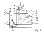
- FIG. 5 a gas turbine system with a CO 2 process has been proposed, which is shown schematically in FIG. 5.
- the quasi-closed gas turbine process charged with CO 2 shown in FIG. 5 has a combustion chamber 2 in which fossil fuel, for example natural gas (CH 4 ) is burned via the feed line 6 with the exclusive addition of pure oxygen (O 2 ) via the feed line 7 becomes.
- fossil fuel for example natural gas (CH 4 )
- O 2 pure oxygen
- the smoke gases 21 emerging from the combustion chamber 2 drive a gas turbine 3, which is connected via a shaft 19 to a generator 5 for generating electricity.
- the compressor 18 is arranged on the common shaft 19 with the turbine 3 and the generator 5.
- a recuperative heat extraction by means of a heat exchanger 14, so that the condensation point of CO 2 is undershot within the condenser 4, as a result of which the compressed and cooled CO 2 changes into the liquid state.
- 10 water can be branched off at the condensation point via a control valve.
- the non-branched, liquefied main portion of CO 2 is compressed by a pump 1 and fed again to the combustion chamber 2 in a correspondingly preheated and compressed form after passing through various recuperator stages 14, 15 and 16.
- According to the invention is a method for operating a gas turbine system with CO 2 as a working medium, in which in at least one combustion chamber, hydrocarbons in an oxygen-enriched CO 2 atmosphere are burned to flue gases, which mainly consist of CO 2 and H 2 0, which are burned within at least a turbine stage downstream of the combustion chamber is expanded and then compressed in a compressor stage and at least partially condensed in a downstream condenser, so that at least parts of the CO 2 and H 2 0 are liquefied and partially discharged together with non-condensed flue gas components and that a non-removed main part is liquid CO 2 compressed by means of a pump unit, preheated in at least one recuperator stage and finally fed back to the combustion chamber, further developed in such a way that the compressed main part CO 2 is pre-expanded to a combustion pressure with which the main part C O 2 is fed to the combustion chamber for combustion.
- flue gases which mainly consist of CO 2 and H 2 0, which are burned within at least a turbine stage downstream of the combustion
- the measure according to the invention of the pre-expansion of the main portion of CO 2 compressed by the pump unit which is typically at a pressure level between 250 and 300 bar after the pump unit, allows the high pressure level of the CO 2 to be reduced to pressure values between 70 and 100 bar safe and efficient operation of the combustion chamber is guaranteed.
- the pressure is typically reduced with the aid of a turbine stage within the quasi-closed CO 2 circuit, which is located downstream of the pump unit and effectively relaxes the CO 2 gases before they enter the combustion chamber.
- the additional turbine stage is preferably arranged in the CO 2 circuit immediately upstream of the combustion chamber and provides the desired pressure reduction there.
- a multi-stage, for example three-stage recuperator is likewise preferably provided, which preheats the CO 2 gases compressed by the pump unit to a temperature desired for combustion.
- Recuperator stages are used for this purpose, for a targeted heat transfer from the hot exhaust gases that expand directly from the turbine stage downstream of the combustion chamber and / or from the warm CO 2 gases emerging from the compressor stage before entering the condenser to those entering for further expansion into the further turbine stage Provide CO 2 gases.
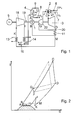
- FIG. 1 shows a schematically illustrated circuit diagram for a quasi-closed CO 2 circuit, which essentially provides a structure similar to that of the CO 2 circuit described in the prior art with reference to FIG. 5.
- the reference symbols used in FIG. 1 indicate components of the same name that have already been introduced and described with reference to FIG. 5.
- a new component of the gas turbine system shown in FIG. 1 is the further turbine stage 22, which is interposed in the quasi-closed CO 2 circuit between the pump unit 1 and the combustion chamber 2.
- the CO 2 gases compressed at high pressure after emerging from the pump unit 1 are passed through a heat exchanger unit 11, in which they are additionally heated by thermal coupling to the hot exhaust gases emerging from the turbine stage 3, before they enter the second turbine stage 22 Expansion.
- the CO 2 gases expanded by the turbine stage 22 then reach the combustion chamber 2 at a pressure between 70 and 100 bar, in which they are available for further combustion.
- the arrangement of the machine group shown in FIG. 1 can, as shown, be single-shaft, i.e. a common arrangement of turbine stage 3, the further turbine stage 22, the pump unit 1, the compressor stage 18 and the generator 5 on a single shaft 19.
- the turbine 22 could also be coupled to the pump unit 1 be on the separate shaft, which preferably rotates at free speed, a further load could also be accommodated, for example an over Inverter coupled electrical machine.
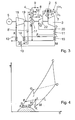
- FIG. 2 shows a T / S diagram which illustrates the thermodynamic properties of the CO 2 circuit shown in FIG. 1.
- the positions designated in the diagram with the letters A, B, C, D, K, I, H, J and M denote working points which correspond to those points shown in FIG. 1.
- a characteristic variable is, for example, the expansion step GJ, which on the one hand leads to a decrease in temperature and at the same time to a reduction in pressure, as a result of which the subsequent combustion process JC is to be carried out within technically permissible range limits.
- the process flow shown in broken lines in FIG. 2 represents a combustion process which, as shown in FIG. 5, does not provide for any expansion preceding the combustion process. It can clearly be seen that, with the pre-expansion according to the invention, similarly high combustion temperatures can be achieved as with the conventional system according to FIG. 5, but at a much lower pressure.
- An essential point in the realization of a quasi-closed CO 2 cycle with a technically acceptable efficiency is the reaching of the beginning of the condensation of CO 2 before entering the condenser 4.
- the beginning of the condensation is defined by the working point H, which is in the T / S diagram
- the point of the envelope is that which limits the liquefied state of CO 2 (hatched area).
- the start of condensation H is achieved via the pre-compression KI in the subcritical gas phase with subsequent intermediate cooling IH. In this way, it is possible to considerably reduce the proportion of the pressure ratio between B and A, ie the pressure increase generated by the pump unit 1, in the total pressure ratio B / K.
- the recuperator preheating of the CO 2 gases emerging from the pump unit 1 before entering the turbine stage 22 consists only of a single-stage recuperator 11, the preheating performance of which is limited due to the high pressure ratios and the associated high thermal capacity of the high-tension CO 2 .
- the CO 2 circuit shown in FIG. 3 provides a three-stage recuperator unit consisting of three heat exchangers 11, 14 and 15.
- an additional intercooler 8 ′ can be provided in the low-pressure region of the CO 2 circuit immediately before entering the condenser 4, which removes the additional heat that cannot be removed by the aforementioned heat exchangers in order to reach the start of condensation of CO 2 at point H.
- a precooler 13 is provided for the purpose of minimizing the power consumption of the compressor 18.
Landscapes
- Engineering & Computer Science (AREA)
- Chemical & Material Sciences (AREA)
- Combustion & Propulsion (AREA)
- Mechanical Engineering (AREA)
- General Engineering & Computer Science (AREA)
- Life Sciences & Earth Sciences (AREA)
- Chemical Kinetics & Catalysis (AREA)
- Sustainable Development (AREA)
- Engine Equipment That Uses Special Cycles (AREA)
- Carbon And Carbon Compounds (AREA)
- Separation By Low-Temperature Treatments (AREA)
- Treating Waste Gases (AREA)
- Gas Separation By Absorption (AREA)
- Organic Low-Molecular-Weight Compounds And Preparation Thereof (AREA)
Abstract
Description
- Fig. 1
- schematisierter CO2-Kreislauf mit einer Rekuperatorstufe,
- Fig. 2
- T/S-Diagramm zum vorstehend beschriebenen Kreislauf,
- Fig. 3
- CO2-Kreislauf mit dreistufiger Rekuperatoreinheit,
- Fig. 4
- T/S-Diagramm zu vorstehendem quasi geschlossenem Kreislauf, sowie
- Fig. 5
- Stand der Technik zu quasi geschlossenem CO2-Kreislauf.
Der andere Teilstrom des von der Pumpeneinheit 2 kommenden CO2-Stromes erfährt seine Vorwärmung durch die Wärme L-M in einem parallel zum Wärmetauscher 14 angeordneten Wärmetauscher 15. Die Temperatur in Punkt F stellt sich somit als Mischwert beider Vorwärmungen ein.
- 1
- Pumpeneinheit
- 2
- Brennkammer
- 3
- Turbinenstufe
- 4
- Kondensator
- 5
- Generator
- 6
- Leitung für CH4
- 7
- Leitung für O2
- 8,9,10
- Ventil
- 8'
- Kühlereinheit
- 11,12,13, 14,15
- Wärmetauscher
- 17
- Leitung nach Pumpe 1
- 18
- Verdichter
- 19
- Welle
- 20
- Abgase
- 21
- Heissgase
- 22
- Turbinenstufe
- ABC...
- Zustandspunkte im T/S-Diagramm von CO2
Claims (13)
- Verfahren zum Betrieb einer Gasturbinenanlage mit CO2 als Arbeitsmittel, bei dem in wenigstens einer Brennkammer (2) Kohlenwasserstoffe in einer mit Sauerstoff angereicherten CO2-Atmosphäre zu Rauchgasen (21), die vorwiegend aus CO2 und H2O bestehen, verbrannt werden, die innerhalb wenigstens einer der Brennkammer (2) nachgeordneten Turbinenstufe (3) expandiert, anschließend in einer Verdichterstufe (18) komprimiert und in einem nachgeordneten Kondensator (4) zumindest teilweise kondensiert werden, sodass zumindest Teile des CO2 und H2O verflüssigt und teilweise zusammen mit nichtkondensierten Rauchgasbestandteilen abgeführt werden und dass ein nicht abgeführter Hauptanteil flüssigen CO2 mittels einer Pumpeneinheit (1) komprimiert, in wenigstens einer Rekuperatorstufe (11) vorgewärmt und der Brennkammer (2) erneut zugeführt wird,
dadurch gekennzeichnet, dass der durch die Pumpeneinheit (1) komprimierte Hauptanteil CO2 auf einen Verbrennungsdruck vorexpandiert wird, mit dem der Hauptanteil CO2 der Brennkammer (2) zur Verbrennung zugeführt wird. - Verfahren nach Anspruch 1,
dadurch gekennzeichnet, dass der durch die Pumpeneinheit (1) komprimierte Hauptanteil CO2 auf den Verbrennungsdruck vorexpandiert wird, nachdem der komprimierte Hauptanteil CO2 wenigstens eine Rekuperatorstufe (11) durchlaufen hat. - Verfahren nach Anspruch 1 oder 2,
dadurch gekennzeichnet, dass der Verbrennungsdruck zwischen 70 bis 100 bar beträgt. - Verfahren nach einem der Ansprüche 1 bis 3,
dadurch gekennzeichnet, dass die nach Kompression der durch die Turbinenstufe (3) expandierten Rauchgase (20) gekühlt werden bevor sie dem Kondensator (4) zugeleitet werden. - Verfahren nach Anspruch 4,
dadurch gekennzeichnet, dass die Kompression und Kühlung der Rauchgase (20) derart erfolgt, dass vor Eintritt der Rauchgase in den Kondensator (4) der Kondensationsbeginn von CO2 in der unterkritischen Gasphase erreicht wird. - Verfahren nach einem der Ansprüche 1 bis 5,
dadurch gekennzeichnet, dass die Vorwärmung des komprimierten Hauptanteils CO2 durch Wärmetausch mit den aus der Turbinenstufe (3) expandiert austretenden Rauchgasen und/oder mit den aus der Verdichterstufe (18) komprimiert austretenden Rauchgasen durchgeführt wird, bevor der komprimierte Hauptanteil CO2 vorexpandiert wird. - Verfahren nach Anspruch 6,
dadurch gekennzeichnet, dass die aus der Turbinenstufe (3) expandiert austretenden Rauchgase vor der Kompression durch die Verdichterstufe (18) und/oder die aus der Verdichterstufe (18) komprimiert austretenden Rauchgase vor der Kondensation durch den Kondensator (4) mit zusätzlichen Kühleinheiten (13, 8')gekühlt werden. - Verfahren nach einem der Ansprüche 1 bis 7,
dadurch gekennzeichnet, dass den aus der Brennkammer (2) austretenden Rauchgasen vor Eintritt in die Turbinenstufe (3) CO2 zugemischt wird, das eine geringere Temperatur aufweist als die der Rauchgase. - Gasturbinenanlage mit CO2 als Arbeitsmittel, mit wenigstens einer Brennkammer (2), in der Kohlenwasserstoffe zusammen mit Sauerstoff innerhalb einer angereicherten CO2-Atmosphäre zu Rauchgasen, die vorwiegend aus CO2 und H2O bestehen, verbrennbar sind, wenigstens einer der Brennkammer (2) nachgeordneten ersten Turbinenstufe (3), innerhalb der die Rauchgase expandieren, mit wenigstens einer der ersten Turbinenstufe (3) nachgeordneten Verdichterstufe (18) sowie einem der Verdichterstufe nachgeordneten Kondensator (4) mit Abscheideeinheiten (8, 9), durch die Teile des innerhalb des Kondensators verflüssigten CO2 sowie nicht kondensierte Rauchgasbestandteile abtrennbar sind, mit einer dem Kondensator (4) nachgeordneten Pumpeneinheit (1), die über wenigstens ein Rekuperator (11) mit der Brennkammer (2) verbunden ist,
dadurch gekennzeichnet, dass zwischen der Pumpeneinheit (1) und der Brennkammer (2) wenigstens eine zweite Turbinenstufe (22) vorgesehen ist, in der der durch die Pumpeneinheit (1) komprimierte Restanteil CO2 auf einen Verbrennungsdruck vorexpandierbar ist, unter dem der Restanteil CO2 der Brennkammer (2) zur Verbrennung zuführbar ist. - Gasturbinenanlage nach Anspruch 9,
dadurch gekennzeichnet, dass die zweite Turbinenstufe (22) nach dem wenigstens einen Rekuperator (11) vor der Brennkammer (2) angeordnet ist. - Gasturbinenanlage nach Anspruch 9 oder 10
dadurch gekennzeichnet, dass der Rekuperator dreistufig aufgebaut ist mit einer ersten Rekuperatorstufe (14) zwischen Verdichterstufe (18) und Kondensator (4), einer zweiten (15) und einer dritten Rekuperatorstufe (11) zwischen der ersten Turbinenstufe (3) und der Verdichterstufe (18). - Gasturbinenanlage nach Anspruch 11,
dadurch gekennzeichnet, dass die erste (14) und die zweite Rekuperatorstufe (15) parallel zueinander geschaltet sind und die dritte Rekuperatorstufe (11) in Serie zur ersten (14) und zweiten Rekuperatorstufe (15). - Gasturbinenanlage nach einem der Ansprüche 9 bis 12,
dadurch gekennzeichnet, dass zwischen der ersten Turbinenstufe (3) und der Verdichterstufe (18) sowie zwischen der Verdichterstufe (18) und dem Kondensator (4) jeweils eine Kühlereinheit (13, 8') angeordnet sind.
Applications Claiming Priority (2)
| Application Number | Priority Date | Filing Date | Title |
|---|---|---|---|
| DE10064270 | 2000-12-22 | ||
| DE10064270A DE10064270A1 (de) | 2000-12-22 | 2000-12-22 | Verfahren zum Betrieb einer Gasturbinenanlage sowie eine diesbezügliche Gasturbinenanlage |
Publications (3)
| Publication Number | Publication Date |
|---|---|
| EP1219800A2 true EP1219800A2 (de) | 2002-07-03 |
| EP1219800A3 EP1219800A3 (de) | 2005-09-07 |
| EP1219800B1 EP1219800B1 (de) | 2009-10-07 |
Family
ID=7668443
Family Applications (1)
| Application Number | Title | Priority Date | Filing Date |
|---|---|---|---|
| EP01128785A Expired - Lifetime EP1219800B1 (de) | 2000-12-22 | 2001-12-04 | Gasturbinenzyklus |
Country Status (5)
| Country | Link |
|---|---|
| US (1) | US6684643B2 (de) |
| EP (1) | EP1219800B1 (de) |
| JP (1) | JP2002201959A (de) |
| AT (1) | ATE445090T1 (de) |
| DE (2) | DE10064270A1 (de) |
Cited By (4)
| Publication number | Priority date | Publication date | Assignee | Title |
|---|---|---|---|---|
| FR2894300A1 (fr) * | 2005-12-07 | 2007-06-08 | Arkopharma Sa Lab | Perfectionnement dans un procede d'hydrogenation catalytique du gaz carbonique de l'athmosphere |
| WO2009002179A1 (en) * | 2007-06-27 | 2008-12-31 | Nebb Technology As | Method and plant for combined production of electric energy and water |
| CN105209732B (zh) * | 2013-03-15 | 2017-05-10 | 帕尔默实验室有限责任公司 | 使用二氧化碳循环工作流体高效发电的系统和方法 |
| CN110195620A (zh) * | 2019-05-31 | 2019-09-03 | 华北电力大学 | 基于超临界二氧化碳的增压流化床联合循环发电系统 |
Families Citing this family (106)
| Publication number | Priority date | Publication date | Assignee | Title |
|---|---|---|---|---|
| DE10231879B4 (de) * | 2002-07-12 | 2017-02-09 | General Electric Technology Gmbh | Verfahren zur Beeinflussung und Kontrolle der Oxidschicht auf thermisch belasteten metallischen Bauteilen von CO2/H2O-Gasturbinenanlagen |
| US7618825B2 (en) | 2002-07-12 | 2009-11-17 | Alstom Technology Ltd. | Method for influencing and monitoring the oxide layer on metallic components of hot CO2/H20 cycle systems |
| CA2497576A1 (en) * | 2002-07-14 | 2004-01-29 | Wolfgang Harazim | Method for the separation of residual gases and working fluid in a combined cycle water/steam process |
| US6802178B2 (en) * | 2002-09-12 | 2004-10-12 | The Boeing Company | Fluid injection and injection method |
| GB2401403B (en) * | 2003-05-08 | 2006-05-31 | Rolls Royce Plc | Carbon dioxide recirculation |
| EP1609958A1 (de) * | 2004-06-22 | 2005-12-28 | Siemens Aktiengesellschaft | Gasturbine mit einem Verdichter und einem Rekuperator |
| DE102006051170B4 (de) * | 2006-10-26 | 2010-02-11 | Takata-Petri Ag | Verfahren und Vorrichtung zur Herstellung eines Gasgenerators und Gasgenerator |
| MY156350A (en) | 2008-03-28 | 2016-02-15 | Exxonmobil Upstream Res Co | Low emission power generation and hydrocarbon recovery systems and methods |
| CA2718803C (en) * | 2008-03-28 | 2016-07-12 | Exxonmobil Upstream Research Company | Low emission power generation and hydrocarbon recovery systems and methods |
| US20100024433A1 (en) * | 2008-07-30 | 2010-02-04 | John Frederick Ackermann | System and method of operating a gas turbine engine with an alternative working fluid |
| US20100024378A1 (en) * | 2008-07-30 | 2010-02-04 | John Frederick Ackermann | System and method of operating a gas turbine engine with an alternative working fluid |
| US20100071878A1 (en) * | 2008-09-19 | 2010-03-25 | General Electric Company | System and method for cooling using system exhaust |
| PL2344738T3 (pl) | 2008-10-14 | 2019-09-30 | Exxonmobil Upstream Research Company | Sposób i układ do sterowania produktami spalania |
| MX345743B (es) | 2009-02-26 | 2017-02-14 | 8 Rivers Capital Llc | Aparato y método para efectuar la combustión de un combustible a alta presión y alta temperatura, y sistema y dispositivo asociados. |
| US10018115B2 (en) | 2009-02-26 | 2018-07-10 | 8 Rivers Capital, Llc | System and method for high efficiency power generation using a carbon dioxide circulating working fluid |
| US8596075B2 (en) * | 2009-02-26 | 2013-12-03 | Palmer Labs, Llc | System and method for high efficiency power generation using a carbon dioxide circulating working fluid |
| CA2777768C (en) | 2009-11-12 | 2016-06-07 | Exxonmobil Upstream Research Company | Low emission power generation and hydrocarbon recovery systems and methods |
| CA2801499C (en) | 2010-07-02 | 2017-01-03 | Exxonmobil Upstream Research Company | Low emission power generation systems and methods |
| CN102959202B (zh) | 2010-07-02 | 2016-08-03 | 埃克森美孚上游研究公司 | 集成系统、发电的方法和联合循环发电系统 |
| JP5906555B2 (ja) | 2010-07-02 | 2016-04-20 | エクソンモービル アップストリーム リサーチ カンパニー | 排ガス再循環方式によるリッチエアの化学量論的燃焼 |
| US9903271B2 (en) | 2010-07-02 | 2018-02-27 | Exxonmobil Upstream Research Company | Low emission triple-cycle power generation and CO2 separation systems and methods |
| US8869889B2 (en) | 2010-09-21 | 2014-10-28 | Palmer Labs, Llc | Method of using carbon dioxide in recovery of formation deposits |
| US20120067054A1 (en) | 2010-09-21 | 2012-03-22 | Palmer Labs, Llc | High efficiency power production methods, assemblies, and systems |
| TWI593872B (zh) | 2011-03-22 | 2017-08-01 | 艾克頌美孚上游研究公司 | 整合系統及產生動力之方法 |
| TWI563166B (en) | 2011-03-22 | 2016-12-21 | Exxonmobil Upstream Res Co | Integrated generation systems and methods for generating power |
| TWI564474B (zh) | 2011-03-22 | 2017-01-01 | 艾克頌美孚上游研究公司 | 於渦輪系統中控制化學計量燃燒的整合系統和使用彼之產生動力的方法 |
| TWI563165B (en) | 2011-03-22 | 2016-12-21 | Exxonmobil Upstream Res Co | Power generation system and method for generating power |
| WO2013067149A1 (en) * | 2011-11-02 | 2013-05-10 | 8 Rivers Capital, Llc | Power generating system and corresponding method |
| WO2013095829A2 (en) | 2011-12-20 | 2013-06-27 | Exxonmobil Upstream Research Company | Enhanced coal-bed methane production |
| JP6185936B2 (ja) * | 2012-02-11 | 2017-08-23 | パルマー ラボ,エルエルシー | 閉鎖型サイクル急冷を伴う部分酸化反応 |
| US9353682B2 (en) | 2012-04-12 | 2016-05-31 | General Electric Company | Methods, systems and apparatus relating to combustion turbine power plants with exhaust gas recirculation |
| US9784185B2 (en) | 2012-04-26 | 2017-10-10 | General Electric Company | System and method for cooling a gas turbine with an exhaust gas provided by the gas turbine |
| US10273880B2 (en) | 2012-04-26 | 2019-04-30 | General Electric Company | System and method of recirculating exhaust gas for use in a plurality of flow paths in a gas turbine engine |
| EP2890885B1 (de) * | 2012-08-30 | 2020-10-07 | Enhanced Energy Group LLC | Kreislaufturbinenmotorantriebssystem |
| US9708977B2 (en) | 2012-12-28 | 2017-07-18 | General Electric Company | System and method for reheat in gas turbine with exhaust gas recirculation |
| US10107495B2 (en) | 2012-11-02 | 2018-10-23 | General Electric Company | Gas turbine combustor control system for stoichiometric combustion in the presence of a diluent |
| US10215412B2 (en) | 2012-11-02 | 2019-02-26 | General Electric Company | System and method for load control with diffusion combustion in a stoichiometric exhaust gas recirculation gas turbine system |
| US9631815B2 (en) | 2012-12-28 | 2017-04-25 | General Electric Company | System and method for a turbine combustor |
| US10161312B2 (en) | 2012-11-02 | 2018-12-25 | General Electric Company | System and method for diffusion combustion with fuel-diluent mixing in a stoichiometric exhaust gas recirculation gas turbine system |
| US9611756B2 (en) | 2012-11-02 | 2017-04-04 | General Electric Company | System and method for protecting components in a gas turbine engine with exhaust gas recirculation |
| US9574496B2 (en) | 2012-12-28 | 2017-02-21 | General Electric Company | System and method for a turbine combustor |
| US9869279B2 (en) | 2012-11-02 | 2018-01-16 | General Electric Company | System and method for a multi-wall turbine combustor |
| US9599070B2 (en) | 2012-11-02 | 2017-03-21 | General Electric Company | System and method for oxidant compression in a stoichiometric exhaust gas recirculation gas turbine system |
| US9803865B2 (en) | 2012-12-28 | 2017-10-31 | General Electric Company | System and method for a turbine combustor |
| JP6531912B2 (ja) | 2012-12-31 | 2019-06-19 | インヴェンティス サーマル テクノロジーズ インコーポレイテッド | 燃焼ガスからの集積二酸化炭素ガス分離の為のプロセス |
| US10208677B2 (en) | 2012-12-31 | 2019-02-19 | General Electric Company | Gas turbine load control system |
| US9581081B2 (en) | 2013-01-13 | 2017-02-28 | General Electric Company | System and method for protecting components in a gas turbine engine with exhaust gas recirculation |
| US9512759B2 (en) | 2013-02-06 | 2016-12-06 | General Electric Company | System and method for catalyst heat utilization for gas turbine with exhaust gas recirculation |
| US9938861B2 (en) | 2013-02-21 | 2018-04-10 | Exxonmobil Upstream Research Company | Fuel combusting method |
| TW201502356A (zh) | 2013-02-21 | 2015-01-16 | Exxonmobil Upstream Res Co | 氣渦輪機排氣中氧之減少 |
| RU2637609C2 (ru) | 2013-02-28 | 2017-12-05 | Эксонмобил Апстрим Рисерч Компани | Система и способ для камеры сгорания турбины |
| US9618261B2 (en) | 2013-03-08 | 2017-04-11 | Exxonmobil Upstream Research Company | Power generation and LNG production |
| TW201500635A (zh) | 2013-03-08 | 2015-01-01 | Exxonmobil Upstream Res Co | 處理廢氣以供用於提高油回收 |
| US20140250945A1 (en) | 2013-03-08 | 2014-09-11 | Richard A. Huntington | Carbon Dioxide Recovery |
| JP6143895B2 (ja) | 2013-03-08 | 2017-06-07 | エクソンモービル アップストリーム リサーチ カンパニー | 発電及びメタンハイドレートからのメタン回収 |
| US9631542B2 (en) | 2013-06-28 | 2017-04-25 | General Electric Company | System and method for exhausting combustion gases from gas turbine engines |
| TWI654368B (zh) | 2013-06-28 | 2019-03-21 | 美商艾克頌美孚上游研究公司 | 用於控制在廢氣再循環氣渦輪機系統中的廢氣流之系統、方法與媒體 |
| US9617914B2 (en) | 2013-06-28 | 2017-04-11 | General Electric Company | Systems and methods for monitoring gas turbine systems having exhaust gas recirculation |
| US9835089B2 (en) | 2013-06-28 | 2017-12-05 | General Electric Company | System and method for a fuel nozzle |
| US9903588B2 (en) | 2013-07-30 | 2018-02-27 | General Electric Company | System and method for barrier in passage of combustor of gas turbine engine with exhaust gas recirculation |
| US9587510B2 (en) | 2013-07-30 | 2017-03-07 | General Electric Company | System and method for a gas turbine engine sensor |
| US9951658B2 (en) | 2013-07-31 | 2018-04-24 | General Electric Company | System and method for an oxidant heating system |
| JP6250332B2 (ja) | 2013-08-27 | 2017-12-20 | 8 リバーズ キャピタル,エルエルシー | ガスタービン設備 |
| US10030588B2 (en) | 2013-12-04 | 2018-07-24 | General Electric Company | Gas turbine combustor diagnostic system and method |
| US9752458B2 (en) | 2013-12-04 | 2017-09-05 | General Electric Company | System and method for a gas turbine engine |
| US10227920B2 (en) | 2014-01-15 | 2019-03-12 | General Electric Company | Gas turbine oxidant separation system |
| US9863267B2 (en) | 2014-01-21 | 2018-01-09 | General Electric Company | System and method of control for a gas turbine engine |
| US9915200B2 (en) | 2014-01-21 | 2018-03-13 | General Electric Company | System and method for controlling the combustion process in a gas turbine operating with exhaust gas recirculation |
| US10079564B2 (en) | 2014-01-27 | 2018-09-18 | General Electric Company | System and method for a stoichiometric exhaust gas recirculation gas turbine system |
| EP2915963A1 (de) * | 2014-03-05 | 2015-09-09 | Siemens Aktiengesellschaft | Heizkraftanlage und Verfahren zum Betreiben einer Heizkraftanlage |
| US10047633B2 (en) | 2014-05-16 | 2018-08-14 | General Electric Company | Bearing housing |
| US9885283B2 (en) * | 2014-06-05 | 2018-02-06 | Rolls-Royce Corporation | Gas turbine engine driven by supercritical power generation system |
| US10655542B2 (en) | 2014-06-30 | 2020-05-19 | General Electric Company | Method and system for startup of gas turbine system drive trains with exhaust gas recirculation |
| US10060359B2 (en) | 2014-06-30 | 2018-08-28 | General Electric Company | Method and system for combustion control for gas turbine system with exhaust gas recirculation |
| US9885290B2 (en) | 2014-06-30 | 2018-02-06 | General Electric Company | Erosion suppression system and method in an exhaust gas recirculation gas turbine system |
| TWI691644B (zh) | 2014-07-08 | 2020-04-21 | 美商八河資本有限公司 | 具改良效率之功率生產方法及系統 |
| MY176626A (en) | 2014-09-09 | 2020-08-19 | 8 Rivers Capital Llc | Production of low pressure liquid carbon dioxide from a power production system and method |
| US11231224B2 (en) | 2014-09-09 | 2022-01-25 | 8 Rivers Capital, Llc | Production of low pressure liquid carbon dioxide from a power production system and method |
| US11686258B2 (en) | 2014-11-12 | 2023-06-27 | 8 Rivers Capital, Llc | Control systems and methods suitable for use with power production systems and methods |
| US10961920B2 (en) | 2018-10-02 | 2021-03-30 | 8 Rivers Capital, Llc | Control systems and methods suitable for use with power production systems and methods |
| MA40950A (fr) | 2014-11-12 | 2017-09-19 | 8 Rivers Capital Llc | Systèmes et procédés de commande appropriés pour une utilisation avec des systèmes et des procédés de production d'énergie |
| US9819292B2 (en) | 2014-12-31 | 2017-11-14 | General Electric Company | Systems and methods to respond to grid overfrequency events for a stoichiometric exhaust recirculation gas turbine |
| US9869247B2 (en) | 2014-12-31 | 2018-01-16 | General Electric Company | Systems and methods of estimating a combustion equivalence ratio in a gas turbine with exhaust gas recirculation |
| US10788212B2 (en) | 2015-01-12 | 2020-09-29 | General Electric Company | System and method for an oxidant passageway in a gas turbine system with exhaust gas recirculation |
| US10094566B2 (en) | 2015-02-04 | 2018-10-09 | General Electric Company | Systems and methods for high volumetric oxidant flow in gas turbine engine with exhaust gas recirculation |
| US10316746B2 (en) | 2015-02-04 | 2019-06-11 | General Electric Company | Turbine system with exhaust gas recirculation, separation and extraction |
| US10253690B2 (en) | 2015-02-04 | 2019-04-09 | General Electric Company | Turbine system with exhaust gas recirculation, separation and extraction |
| US10267270B2 (en) | 2015-02-06 | 2019-04-23 | General Electric Company | Systems and methods for carbon black production with a gas turbine engine having exhaust gas recirculation |
| US10145269B2 (en) | 2015-03-04 | 2018-12-04 | General Electric Company | System and method for cooling discharge flow |
| US10480792B2 (en) | 2015-03-06 | 2019-11-19 | General Electric Company | Fuel staging in a gas turbine engine |
| CN107849976B (zh) | 2015-06-15 | 2021-11-02 | 八河流资产有限责任公司 | 用于启动发电设备的系统和方法 |
| MX2018002550A (es) | 2015-09-01 | 2018-08-15 | 8 Rivers Capital Llc | Sistemas y metodos para la produccion de energia usando ciclos de co2 anidados. |
| AU2016332456A1 (en) | 2015-09-30 | 2018-05-17 | Florida Turbine Technologies, Inc. | CAES combustor test facility |
| MX2018010022A (es) | 2016-02-18 | 2018-12-10 | 8 Rivers Capital Llc | Sistema y metodo para la produccion de energia incluyendo metanacion. |
| EP4234906A3 (de) | 2016-02-26 | 2023-11-08 | 8 Rivers Capital, LLC | Systeme und verfahren zur steuerung eines kraftwerks |
| PL3445955T3 (pl) | 2016-04-21 | 2022-09-19 | 8 Rivers Capital, Llc | Układ i sposób utleniania gazów węglowodorowych |
| MX2019002888A (es) | 2016-09-13 | 2019-07-04 | 8 Rivers Capital Llc | Sistema y metodo para la produccion de energia utilizando oxidacion parcial. |
| EP3714146B1 (de) | 2017-08-28 | 2023-08-23 | 8 Rivers Capital, LLC | Hitzearme optimierung von rekuperativen überkritischen co2 -leistungszyklen |
| ES2970038T3 (es) | 2018-03-02 | 2024-05-24 | 8 Rivers Capital Llc | Sistemas y métodos para la producción de energía usando un fluido de trabajo de dióxido de carbono |
| WO2019223985A1 (de) | 2018-05-22 | 2019-11-28 | Siemens Aktiengesellschaft | Erweiterter gasturbinenprozess mit expander |
| WO2021079324A1 (en) | 2019-10-22 | 2021-04-29 | 8 Rivers Capital, Llc | Control schemes for thermal management of power production systems and methods |
| EP3872233A1 (de) * | 2020-02-26 | 2021-09-01 | Doosan Lentjes GmbH | Verfahren zur speicherung von energie und energiespeichersystem |
| JP7592893B2 (ja) * | 2021-04-26 | 2024-12-02 | ヌオーヴォ・ピニォーネ・テクノロジー・ソチエタ・レスポンサビリタ・リミタータ | 燃料から機械エネルギーへの高効率変換のためのプラント |
| IT202100010490A1 (it) * | 2021-04-26 | 2022-10-26 | Nuovo Pignone Tecnologie Srl | Plant for high-efficiency fuel to mechanical energy conversion. |
| EP4649228A1 (de) * | 2023-01-13 | 2025-11-19 | Arbor Energy And Resources Corporation | Integriertes kohlenstoffsequestrierungs- und stromerzeugungssystem sowie verfahren zur verwendung |
| CN119914413B (zh) * | 2023-10-31 | 2025-10-21 | 中国科学院工程热物理研究所 | 二甲醚生产与自冷凝跨临界co2阿拉姆循环联合系统、方法 |
Family Cites Families (6)
| Publication number | Priority date | Publication date | Assignee | Title |
|---|---|---|---|---|
| US3736745A (en) * | 1971-06-09 | 1973-06-05 | H Karig | Supercritical thermal power system using combustion gases for working fluid |
| US4434613A (en) * | 1981-09-02 | 1984-03-06 | General Electric Company | Closed cycle gas turbine for gaseous production |
| US4498289A (en) * | 1982-12-27 | 1985-02-12 | Ian Osgerby | Carbon dioxide power cycle |
| US4528811A (en) * | 1983-06-03 | 1985-07-16 | General Electric Co. | Closed-cycle gas turbine chemical processor |
| DE4303174A1 (de) * | 1993-02-04 | 1994-08-18 | Joachim Dipl Ing Schwieger | Verfahren zum Erzeugen elektrischer Energie |
| DE59810673D1 (de) * | 1998-04-28 | 2004-03-04 | Asea Brown Boveri | Kraftwerksanlage mit einem CO2-Prozess |
-
2000
- 2000-12-22 DE DE10064270A patent/DE10064270A1/de not_active Withdrawn
-
2001
- 2001-12-04 AT AT01128785T patent/ATE445090T1/de not_active IP Right Cessation
- 2001-12-04 EP EP01128785A patent/EP1219800B1/de not_active Expired - Lifetime
- 2001-12-04 DE DE50115157T patent/DE50115157D1/de not_active Expired - Lifetime
- 2001-12-06 US US10/003,418 patent/US6684643B2/en not_active Expired - Lifetime
- 2001-12-21 JP JP2001390385A patent/JP2002201959A/ja active Pending
Cited By (6)
| Publication number | Priority date | Publication date | Assignee | Title |
|---|---|---|---|---|
| FR2894300A1 (fr) * | 2005-12-07 | 2007-06-08 | Arkopharma Sa Lab | Perfectionnement dans un procede d'hydrogenation catalytique du gaz carbonique de l'athmosphere |
| WO2007065930A1 (fr) * | 2005-12-07 | 2007-06-14 | Imarko Research S.A. | Perfectionnement dans un procédé d'hydrogénation catalytique du gaz carbonique de l'atmosphère |
| WO2009002179A1 (en) * | 2007-06-27 | 2008-12-31 | Nebb Technology As | Method and plant for combined production of electric energy and water |
| CN105209732B (zh) * | 2013-03-15 | 2017-05-10 | 帕尔默实验室有限责任公司 | 使用二氧化碳循环工作流体高效发电的系统和方法 |
| CN110195620A (zh) * | 2019-05-31 | 2019-09-03 | 华北电力大学 | 基于超临界二氧化碳的增压流化床联合循环发电系统 |
| CN110195620B (zh) * | 2019-05-31 | 2020-10-30 | 华北电力大学 | 基于超临界二氧化碳的增压流化床联合循环发电系统 |
Also Published As
| Publication number | Publication date |
|---|---|
| US20020134085A1 (en) | 2002-09-26 |
| EP1219800B1 (de) | 2009-10-07 |
| DE50115157D1 (de) | 2009-11-19 |
| JP2002201959A (ja) | 2002-07-19 |
| DE10064270A1 (de) | 2002-07-11 |
| ATE445090T1 (de) | 2009-10-15 |
| EP1219800A3 (de) | 2005-09-07 |
| US6684643B2 (en) | 2004-02-03 |
Similar Documents
| Publication | Publication Date | Title |
|---|---|---|
| EP1219800B1 (de) | Gasturbinenzyklus | |
| DE60036327T2 (de) | Verfahren zur Luftzerlegung mit einer Brennkraftmaschine zur Herstellung von Luftgasen und elektrischer Energie | |
| DE102004039164A1 (de) | Verfahren zur Erzeugung von Energie in einer eine Gasturbine umfassenden Energieerzeugungsanlage sowie Energieerzeugungsanlage zur Durchführung des Verfahrens | |
| DE102014105237B3 (de) | Verfahren und Vorrichtung zum Speichern und Rückgewinnen von Energie | |
| DE60033889T2 (de) | Verfahren zur Energieerzeugung mit einem thermochemischen Rückgewinnungskreislauf | |
| EP0924410B1 (de) | Verfahren zum Betrieb einer Gasturbogruppe | |
| EP0518868B1 (de) | Verfahren und anlage zur erzeugung mechanischer energie | |
| DE69931548T2 (de) | Turbinenanlage | |
| EP0553125B1 (de) | Verfahren und anlage zur kombinierten erzeugung elektrischer und mechanischer energie | |
| DE69918492T2 (de) | Turbine à gaz à chauffage indirect integree à une unite de separation des gaz de l'air | |
| EP0424660B1 (de) | Gas/Dampf-Kraftwerksanlage | |
| DE4301100C2 (de) | Verfahren zum Betrieb eines Kombikraftwerkes mit Kohle- oder Oelvergasung | |
| DE2743830C2 (de) | Verfahren zum Betreiben einer kombinierten Gas-Dampfkraftanlage und Gas-Dampfkraftanlage zur Durchführung des Verfahrens | |
| DE2524723C2 (de) | Kombiniertes Gas-Dampf-Kraftwerk mit Druckgaserzeuger | |
| DE19654472A1 (de) | Verfahren zur Kühlung von thermisch hochbelasteten Aggregaten einer Gasturbogruppe | |
| EP0666412B1 (de) | Verfahren zur Kühlung von Kühlluft für eine Gasturbine | |
| EP0530519B1 (de) | Kraftwerksanlage mit nuklearer und fossiler Feuerung | |
| DE4303174A1 (de) | Verfahren zum Erzeugen elektrischer Energie | |
| DE3413241A1 (de) | Kombiniertes gas-/dampfturbinenkraftwerk mit co/o(pfeil abwaerts)2(pfeil abwaerts)-verbrennung | |
| EP0489270B1 (de) | Verfahren zur Druckverminderung eines Gases aus einem Primärnetz | |
| EP1518040A1 (de) | Dampfkraftwerk | |
| EP1482131A1 (de) | Dampfkraft-/Arbeitsprozess mit indirekter Energiezufuhr für die Elektroenergiegewinnung im Kreisprozess sowie Anordnung zu seiner Durchführung | |
| AT395635B (de) | Kombinierte gasturbine - dampfkraftanlage | |
| DE19732268A1 (de) | Gasturbine und Verfahren zum Betreiben derselben sowie Verfahren und Vorrichtung zum Verdichten eines Arbeitsgases | |
| DE4143226A1 (de) | Gasturbogruppe |
Legal Events
| Date | Code | Title | Description |
|---|---|---|---|
| PUAI | Public reference made under article 153(3) epc to a published international application that has entered the european phase |
Free format text: ORIGINAL CODE: 0009012 |
|
| AK | Designated contracting states |
Kind code of ref document: A2 Designated state(s): AT BE CH CY DE DK ES FI FR GB GR IE IT LI LU MC NL PT SE TR |
|
| AX | Request for extension of the european patent |
Free format text: AL;LT;LV;MK;RO;SI |
|
| RAP1 | Party data changed (applicant data changed or rights of an application transferred) |
Owner name: ALSTOM (SWITZERLAND) LTD |
|
| RAP1 | Party data changed (applicant data changed or rights of an application transferred) |
Owner name: ALSTOM TECHNOLOGY LTD |
|
| PUAL | Search report despatched |
Free format text: ORIGINAL CODE: 0009013 |
|
| AK | Designated contracting states |
Kind code of ref document: A3 Designated state(s): AT BE CH CY DE DK ES FI FR GB GR IE IT LI LU MC NL PT SE TR |
|
| AX | Request for extension of the european patent |
Extension state: AL LT LV MK RO SI |
|
| 17P | Request for examination filed |
Effective date: 20060217 |
|
| AKX | Designation fees paid |
Designated state(s): AT BE CH CY DE DK ES FI FR GB GR IE IT LI LU MC NL PT SE TR |
|
| GRAP | Despatch of communication of intention to grant a patent |
Free format text: ORIGINAL CODE: EPIDOSNIGR1 |
|
| GRAS | Grant fee paid |
Free format text: ORIGINAL CODE: EPIDOSNIGR3 |
|
| GRAA | (expected) grant |
Free format text: ORIGINAL CODE: 0009210 |
|
| AK | Designated contracting states |
Kind code of ref document: B1 Designated state(s): AT BE CH CY DE DK ES FI FR GB GR IE IT LI LU MC NL PT SE TR |
|
| REG | Reference to a national code |
Ref country code: GB Ref legal event code: FG4D Free format text: NOT ENGLISH |
|
| REG | Reference to a national code |
Ref country code: CH Ref legal event code: EP |
|
| REG | Reference to a national code |
Ref country code: IE Ref legal event code: FG4D |
|
| REF | Corresponds to: |
Ref document number: 50115157 Country of ref document: DE Date of ref document: 20091119 Kind code of ref document: P |
|
| NLV1 | Nl: lapsed or annulled due to failure to fulfill the requirements of art. 29p and 29m of the patents act | ||
| PG25 | Lapsed in a contracting state [announced via postgrant information from national office to epo] |
Ref country code: FI Free format text: LAPSE BECAUSE OF FAILURE TO SUBMIT A TRANSLATION OF THE DESCRIPTION OR TO PAY THE FEE WITHIN THE PRESCRIBED TIME-LIMIT Effective date: 20091007 Ref country code: PT Free format text: LAPSE BECAUSE OF FAILURE TO SUBMIT A TRANSLATION OF THE DESCRIPTION OR TO PAY THE FEE WITHIN THE PRESCRIBED TIME-LIMIT Effective date: 20100208 Ref country code: ES Free format text: LAPSE BECAUSE OF FAILURE TO SUBMIT A TRANSLATION OF THE DESCRIPTION OR TO PAY THE FEE WITHIN THE PRESCRIBED TIME-LIMIT Effective date: 20100118 Ref country code: SE Free format text: LAPSE BECAUSE OF FAILURE TO SUBMIT A TRANSLATION OF THE DESCRIPTION OR TO PAY THE FEE WITHIN THE PRESCRIBED TIME-LIMIT Effective date: 20091007 |
|
| REG | Reference to a national code |
Ref country code: IE Ref legal event code: FD4D |
|
| BERE | Be: lapsed |
Owner name: ALSTOM TECHNOLOGY LTD Effective date: 20091231 |
|
| PG25 | Lapsed in a contracting state [announced via postgrant information from national office to epo] |
Ref country code: DK Free format text: LAPSE BECAUSE OF FAILURE TO SUBMIT A TRANSLATION OF THE DESCRIPTION OR TO PAY THE FEE WITHIN THE PRESCRIBED TIME-LIMIT Effective date: 20091007 Ref country code: MC Free format text: LAPSE BECAUSE OF NON-PAYMENT OF DUE FEES Effective date: 20100701 Ref country code: IE Free format text: LAPSE BECAUSE OF FAILURE TO SUBMIT A TRANSLATION OF THE DESCRIPTION OR TO PAY THE FEE WITHIN THE PRESCRIBED TIME-LIMIT Effective date: 20091007 Ref country code: NL Free format text: LAPSE BECAUSE OF FAILURE TO SUBMIT A TRANSLATION OF THE DESCRIPTION OR TO PAY THE FEE WITHIN THE PRESCRIBED TIME-LIMIT Effective date: 20091007 |
|
| REG | Reference to a national code |
Ref country code: CH Ref legal event code: PL |
|
| PLBE | No opposition filed within time limit |
Free format text: ORIGINAL CODE: 0009261 |
|
| STAA | Information on the status of an ep patent application or granted ep patent |
Free format text: STATUS: NO OPPOSITION FILED WITHIN TIME LIMIT |
|
| 26N | No opposition filed |
Effective date: 20100708 |
|
| REG | Reference to a national code |
Ref country code: FR Ref legal event code: ST Effective date: 20100831 |
|
| PG25 | Lapsed in a contracting state [announced via postgrant information from national office to epo] |
Ref country code: LI Free format text: LAPSE BECAUSE OF NON-PAYMENT OF DUE FEES Effective date: 20091231 Ref country code: BE Free format text: LAPSE BECAUSE OF NON-PAYMENT OF DUE FEES Effective date: 20091231 Ref country code: CH Free format text: LAPSE BECAUSE OF NON-PAYMENT OF DUE FEES Effective date: 20091231 Ref country code: FR Free format text: LAPSE BECAUSE OF NON-PAYMENT OF DUE FEES Effective date: 20091231 Ref country code: GR Free format text: LAPSE BECAUSE OF FAILURE TO SUBMIT A TRANSLATION OF THE DESCRIPTION OR TO PAY THE FEE WITHIN THE PRESCRIBED TIME-LIMIT Effective date: 20100108 |
|
| PG25 | Lapsed in a contracting state [announced via postgrant information from national office to epo] |
Ref country code: IT Free format text: LAPSE BECAUSE OF FAILURE TO SUBMIT A TRANSLATION OF THE DESCRIPTION OR TO PAY THE FEE WITHIN THE PRESCRIBED TIME-LIMIT Effective date: 20091007 |
|
| PG25 | Lapsed in a contracting state [announced via postgrant information from national office to epo] |
Ref country code: LU Free format text: LAPSE BECAUSE OF NON-PAYMENT OF DUE FEES Effective date: 20091204 |
|
| PG25 | Lapsed in a contracting state [announced via postgrant information from national office to epo] |
Ref country code: AT Free format text: LAPSE BECAUSE OF NON-PAYMENT OF DUE FEES Effective date: 20091204 |
|
| PG25 | Lapsed in a contracting state [announced via postgrant information from national office to epo] |
Ref country code: TR Free format text: LAPSE BECAUSE OF FAILURE TO SUBMIT A TRANSLATION OF THE DESCRIPTION OR TO PAY THE FEE WITHIN THE PRESCRIBED TIME-LIMIT Effective date: 20091007 |
|
| PG25 | Lapsed in a contracting state [announced via postgrant information from national office to epo] |
Ref country code: CY Free format text: LAPSE BECAUSE OF FAILURE TO SUBMIT A TRANSLATION OF THE DESCRIPTION OR TO PAY THE FEE WITHIN THE PRESCRIBED TIME-LIMIT Effective date: 20091007 |
|
| REG | Reference to a national code |
Ref country code: DE Ref legal event code: R082 Ref document number: 50115157 Country of ref document: DE Representative=s name: ROESLER, UWE, DIPL.-PHYS.UNIV., DE Ref country code: DE Ref legal event code: R081 Ref document number: 50115157 Country of ref document: DE Owner name: GENERAL ELECTRIC TECHNOLOGY GMBH, CH Free format text: FORMER OWNER: ALSTOM TECHNOLOGY LTD., BADEN, CH Ref country code: DE Ref legal event code: R081 Ref document number: 50115157 Country of ref document: DE Owner name: ANSALDO ENERGIA IP UK LIMITED, GB Free format text: FORMER OWNER: ALSTOM TECHNOLOGY LTD., BADEN, CH |
|
| PGFP | Annual fee paid to national office [announced via postgrant information from national office to epo] |
Ref country code: DE Payment date: 20161213 Year of fee payment: 16 Ref country code: GB Payment date: 20161222 Year of fee payment: 16 |
|
| REG | Reference to a national code |
Ref country code: DE Ref legal event code: R082 Ref document number: 50115157 Country of ref document: DE Representative=s name: ROESLER, UWE, DIPL.-PHYS.UNIV., DE Ref country code: DE Ref legal event code: R081 Ref document number: 50115157 Country of ref document: DE Owner name: ANSALDO ENERGIA IP UK LIMITED, GB Free format text: FORMER OWNER: GENERAL ELECTRIC TECHNOLOGY GMBH, BADEN, CH |
|
| REG | Reference to a national code |
Ref country code: GB Ref legal event code: 732E Free format text: REGISTERED BETWEEN 20170824 AND 20170830 |
|
| REG | Reference to a national code |
Ref country code: DE Ref legal event code: R119 Ref document number: 50115157 Country of ref document: DE |
|
| GBPC | Gb: european patent ceased through non-payment of renewal fee |
Effective date: 20171204 |
|
| PG25 | Lapsed in a contracting state [announced via postgrant information from national office to epo] |
Ref country code: DE Free format text: LAPSE BECAUSE OF NON-PAYMENT OF DUE FEES Effective date: 20180703 |
|
| PG25 | Lapsed in a contracting state [announced via postgrant information from national office to epo] |
Ref country code: GB Free format text: LAPSE BECAUSE OF NON-PAYMENT OF DUE FEES Effective date: 20171204 |