EP1218760B1 - Strommessung in einem fahrzeug mittels eines batteriekabels als vorwiderstand - Google Patents
Strommessung in einem fahrzeug mittels eines batteriekabels als vorwiderstand Download PDFInfo
- Publication number
- EP1218760B1 EP1218760B1 EP00968598A EP00968598A EP1218760B1 EP 1218760 B1 EP1218760 B1 EP 1218760B1 EP 00968598 A EP00968598 A EP 00968598A EP 00968598 A EP00968598 A EP 00968598A EP 1218760 B1 EP1218760 B1 EP 1218760B1
- Authority
- EP
- European Patent Office
- Prior art keywords
- voltage
- battery
- amplifier
- cable
- current
- Prior art date
- Legal status (The legal status is an assumption and is not a legal conclusion. Google has not performed a legal analysis and makes no representation as to the accuracy of the status listed.)
- Expired - Lifetime
Links
Images

Classifications
-
- G—PHYSICS
- G01—MEASURING; TESTING
- G01R—MEASURING ELECTRIC VARIABLES; MEASURING MAGNETIC VARIABLES
- G01R31/00—Arrangements for testing electric properties; Arrangements for locating electric faults; Arrangements for electrical testing characterised by what is being tested not provided for elsewhere
- G01R31/005—Testing of electric installations on transport means
- G01R31/006—Testing of electric installations on transport means on road vehicles, e.g. automobiles or trucks
-
- G—PHYSICS
- G01—MEASURING; TESTING
- G01R—MEASURING ELECTRIC VARIABLES; MEASURING MAGNETIC VARIABLES
- G01R1/00—Details of instruments or arrangements of the types included in groups G01R5/00 - G01R13/00 and G01R31/00
- G01R1/20—Modifications of basic electric elements for use in electric measuring instruments; Structural combinations of such elements with such instruments
- G01R1/203—Resistors used for electric measuring, e.g. decade resistors standards, resistors for comparators, series resistors, shunts
Definitions
- the present invention relates to the measurement of electrical current and particularly to measuring current in a vehicle using one of the cables of a vehicle connected to its battery.
- an electrical current has to be measured and monitored.
- vehicles having a battery used for various purposes such as starting an engine or powering electrical systems such as lights and instruments
- current is measured and monitored for instrumentation control purposes.
- U.S. Patent 4,937,528 entitled “Method for Monitoring Automotive Battery Status”, which is assigned to the assignee of the subject application describes an analysis system in which current is measured and monitored during operation of an automobile to determine capacity, state of charge and certain fault conditions of the vehicle's battery.
- Such a system can also be used for other types of vehicles, such as aircraft, buses, etc.
- One technique for electrical current measurement and/or monitoring the current flow in the electrical systems of automotive, aircraft and other vehicles requires a sensor that effectively measures the magnetic field caused by a current flowing through a conductor.
- Some of the commonly used sensor types are Hall effect and inductive devices.
- Another technique, used in the aforesaid patent, is that of a precision resistance shunt of a known resistance value which is placed in series with a part of the conductor carrying the current to be measured. By measuring the voltage across the shunt and knowing its resistance, the current can be calculated.
- a shunt While the use of a shunt is adequate for many purposes, it has disadvantages in that it requires the cost of the shunt itself and additional electrical connections. More importantly, the shunt results in a power loss which is a product of the square of the current value times the resistance value of the shunt. For example, if a one ohm shunt is used to measure current flow in the electrical system of an automobile, the power loss due to the resistance heating of the shunt would be substantial and could cause unnecessary fuel consumption in the vehicle.
- US-A-4937528 discloses apparatus for measuring current in a vehicle battery using a shunt.
- US-A-3660759 discloses apparatus for testing an automotive battery wherein the battery cable may form the shunt.
- US-A-4186339 discloses apparatus for monitoring current flow from a battery and describes a reference voltage source and the use of different current scales in accordance with the expected battery current flow.
- apparatus for monitoring current flow to a battery installed in a vehicle the battery having positive and negative terminals, the apparatus comprising:
- the apparatus further comprises:
- a third amplifier receives a signal output by the digital potentiometer and outputs the signal input to the first-mentioned amplifier, the third amplifier having a reference terminal to set its operating point and wherein a voltage centred on zero is provided for the input to said reference terminal to offset for circuit tolerance variations.
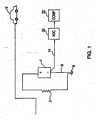
- the body of a vehicle such as an automobile, aircraft, bus, or boat is designated V.
- the vehicle body is generally of metal and has an electrical ground reference 8 which can be the vehicle frame or chassis.
- a battery 1 of any conventional type, such as lead-acid, used to supply power for normal purposes such as starting, lighting and instrumentation (SLI).
- Battery 1 has the usual positive and negative terminals.
- Reference numeral 2 designate the electrical load of the vehicle that is serviced by the battery.
- the load 2 is shown connected between the battery positive terminal and the electrical reference ground 8 and can be of any suitable type, such as a starter motor, lights, air conditioning system, etc.
- the battery charging system which is of any conventional type, is not shown.
- An electrical conductor cable 3 is connected between the battery negative terminal and the ground reference 8. This is commonly called the ground return cable.
- Cable 3 is a necessary component of the electrical system found in virtually all vehicles having a battery, In accordance with one embodiment of the invention; cable 3 is made to have a known resistance value. This can be, for example, 0.1 milliohms, although any other suitable value can be used depending upon the overall requirements of the vehicle electrical system. Any current flowing into battery 1, such as during charging, or flowing out of the battery, such as during operation of an electrical system, will flow through the cable 3.
- the voltage drop across cable 3 is used. This voltage will vary depending upon the current flow to and from battery 1.
- the voltage appearing across cable 3, which is an analog quantity, is applied over lead 14 to the input of an analog - digital converter 20 which converts it to a digital quantity.
- the digital quantity is supplied to a computer 22 which has programmed therein the resistance value of the cable 3.
- the arrangement shown in Fig. 1 is capable of monitoring the current without the need for any additional component, such as a shunt used with cable 3, which would consume power, or another type of sensor and any connections that they would require.
- the computed current value is available for any desired purpose. There can be a continuous monitoring of the current flow so that information can be supplied to a battery monitoring system of the type disclosed in the aforesaid patent. All of this is accomplished simply and efficiently.
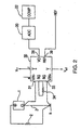
- Fig. 2 shows another embodiment of the invention that uses a differential current sensor.
- Element 1 is the vehicle battery
- 2 is the vehicle electrical system load supplied by the battery
- 3 is the cable of known resistance value between the battery's negative terminal and the vehicle electrical ground reference 8.
- An instrumentation amplifier 30 has input terminals 31 and 33 connected respectively to the battery negative terminal and the vehicle electrical ground reference 8.
- the instrumentation amplifier 30 can be, for example, of type AWA 118 manufactured by Burr-Brown.
- the input terminals of such a device have a high input impedance.
- the device 30 also has a resistor 34 connected between appropriate terminals to set its gain.
- Device 30 is also shown as receiving a positive operating voltage from a source Vcc and a negative voltage from a source Vdd.
- Device 30 has an output terminal 38 and a reference terminal 39.
- the voltage across cable 3, corresponding to the current flowing through it, is sensed at the high impedance input terminal 31 of the device 30.
- the gain of device 30 is set by resistor 34 to any suitable value, for example in a range of ⁇ 5 volts output (corresponding to the range of the voltage change across cable 3) to correspond to a range of ⁇ 1000 Amperes of current flowing through the cable.
- the output 38 on the device terminal will be an analog voltage which corresponds to the current flowing through cable 3 into and out of the battery. This is supplied to the A/D converter 20 whose output digital signal is supplied to the computer 22 which is programmed to be able to make the current flow computation.
- the reference terminal 39 of device 30 can be adjusted to offset the device 30 output range. If a bipolar A/D converter 20 is used, the reference terminal 39 of device 30 would be set near zero depending on the internal offset of the amplifier device itself. If the converter 20 is unipolar, the reference terminal 39 would be set at the center of the voltage range of the converter.
- the output 38 of the amplifier device 30 can be amplified further to obtain smaller current ranges such as, for example, ⁇ 100 Amperes and ⁇ 10 Amperes. That is, circuit resolution is increased for a higher voltage input to A/D converter 20 since it can be resolved into finer increments.
- the computer 22 can be programmed with an algorithm to automatically determine which of the ranges to use for the battery current at any given time.
- Fig. 3 shows another embodiment of the invention which operates without knowing the exact resistance value of the cable. This is to provide three main functions for monitoring the battery current of a vehicle. The first function is to measure the current going both in and out of the battery. The second is an auto-calibration circuit which calibrates the battery's return cable used as a shunt to allow accurate measurement of the battery's current. The auto-cal circuit eliminates the need for knowing the exact impedance (resistance) of the cable. This can vary with manufacturing tolerances and also varies depending on the model of the car. The third function is to provide for automatic compensation for component tolerances that would cause an offset when the system input current is zero.
- Fig. 3 common elements are identified with the same reference numerals applied as used in Figs. 1 and 2 ; specifically, as before, 1 indicates the car battery, 2 the vehicle electrical load, 3 the ground return cable and 8 the ground reference connection point of the vehicle frame.
- an auto-zero relay 104 whose operation is controlled by digital signals from computer 22 in accordance with an application program or by a dedicated digital controller having an embedded program. In the following description the term controller is used but it should be understood that the controller can be part of a computer.
- One contact of relay 104 is connected to the negative terminal of battery 1, to which cable 3 is connected, and the other contact to the ground reference point 8.
- the relay 104 center arm is connected to a resistor 105 which serves as the input to a variable voltage divider which includes an adjustable digitally controlled potentiometer 106 having a resistor 107 connected between its output terminal L and ground 8.
- the center arm pick off point of potentiometer 106 can be set by applying digital signals from the controller to its input terminals.
- a resistor 108 connects the output of the voltage divider 105 - 107 to the positive input terminal of an instrumentation amplifier 111 which has an input resistor 109 between its negative input terminal and the negative battery terminal to which cable 3 is connected.
- Amplifier 111 can be of type INA 118 made by Burr-Brown.
- resistor 110 at the input of amplifier 111 to set its gain.
- Resistors 112 and 113 connected between the circuit positive voltage supply point and ground are part of a voltage divider for the auto-zero circuit which includes another adjustable digital potentiometer 114 controlled by the controller.
- Resistor 115 at the output of potentiometer 1 14 is connected to the upper end of a voltage divider formed by resistors 116 and 117 whose junction receives voltage from the circuit negative supply.
- the upper end of this voltage divider is connected to the input of a buffer amplifier 119 whose output is connected to ground by resistors 120 and 121. This provides a negative bias for the auto-zero circuit enabling the voltage at the input of amplifier 119 to swing negative without the need of the output voltage of potentiometer 114 to go negative.
- Each of amplifiers 122 and 123 has its input connected to the output V o of amplifier 111.
- Each of the amplifiers 122 and 123 has a selected gain to have an output to correspond to a current range.
- amplifier 123 has a gain of 100 representing a current range of ⁇ 10 Amps and amplifier 122 a gain of 10 to provide an output representing ⁇ 100 Amps.
- the output of each of the amplifiers 122 and 123 is connected to the ADC 20 of Fig. 1 which is a data input to the controller or computer 22.
- a transistor 125 such as a PMOS device, along with its bias resistors 126 and 127 is a reference current source.
- a signal is applied from the controller to the lower end of resistor 127 to turn on the device 125 and produce a voltage across a resistor 128 which is a precision resistor of known value, for example 10 ohms.
- the output voltage of device 125 across resistor 128 corresponds to a current value that can be computed since the value of resistor 128 is known.
- This voltage on line 129 is applied to the ADC and is used by the controller for calibrating the system gain.
- the output of amplifier 111 also is applied to the inputs of amplifiers 122 and 123 of different gain and the outputs of these amplifiers are applied to ADC 20.
- the outputs of amplifiers 122 and 123 which also can be over a ⁇ 5V range, correspond to other ranges of the current flow as indicated above.
- Adjustment of the divider 105-107 is accomplished by using the reference current from source 125 that can be switched on and off. As previously described, since the value of precision resistor 128 is known the controller can calculate a current from the measured voltage across resistor 128. The controller periodically switches the current from source 125 on and off, and the difference between the voltage across resistor 128 and that at the output of the ⁇ 10 Amp amplifier 123 is measured. Based on this difference the controller adjusts divider 105-107, by moving the arm of the digitally controlled potentiometer 106, so as to obtain an output equal to the switched reference current. For example, If the reference current is a 1 amp pulse the voltage pulse at the output of amplifier 123 ( ⁇ 10 amp range) would be 500 mV peak to peak since ⁇ 5 volts (the range of the amplifiers output) represents ⁇ 10 amps.
- the controller starts the auto-zero function. It first turns on relay 104, i.e., the center arm would go up. This disconnects the input of the voltage divider 105-107 form the battery cable 3 and places a short circuit across the input to the current measuring circuit. The controller then operates to adjust the center arm of digital potentiometer 114 to set the input voltage at the amplifier 111 reference terminal 111 R. This allows the output of amplifier 111 to be adjusted to compensate for internal offsets. This is adjusted until the output of amplifier 111 makes the output at the ⁇ 10 Amp amplifier 123 zero, within a predetermined tolerance.
- the auto-zero voltage at the output of potentiometer 114 is combined with negative voltage from the junction of voltage divider resistors 117 and 118 to provide a voltage centered on zero for the input to the reference terminal 111R of amplifier 111.
- Amplifier 119 along with resistors 120 and 121 provides a low impedance drive for the reference terminal 111 R of amplifier 111.
- By using the biasing network of resistors 117 and 118 a positive to negative swing is obtained for the amplifier 111 reference terminal without having the output of potentiometer 114 go negative.
- the center arm of the digital potentiometer 114 cannot go below the voltage at terminal 114G of digital potentiometer 114 in accordance with manufacturing specifications.
- the reference voltage needed for amplifier 111 can be set to be at the center of the range of digital potentiometer 114.
- the adjustment range is set to cover the expected tolerance variations of the ground return cable 3 and various offset voltages caused by component tolerances.
- Each of the circuits of Figs. 1-3 is able to measure and monitor the current flow into and from the vehicle battery without the need for any additional components such as a current shunt.
- Modifications of the circuits shown include the use of the cable connected to the battery positive terminal or the use of both cables. For the latter, there can be measurement of the voltage across one cable for battery current flow input and across the other terminal for current flow output. Also, the computer 22 can be provided with a data lookup table to directly convert voltage input data to a current value rather than making the Ohm's law type calculation.
Landscapes
- Chemical & Material Sciences (AREA)
- Engineering & Computer Science (AREA)
- Combustion & Propulsion (AREA)
- Physics & Mathematics (AREA)
- General Physics & Mathematics (AREA)
- Measurement Of Current Or Voltage (AREA)
- Secondary Cells (AREA)
- Tests Of Electric Status Of Batteries (AREA)
- Measurement Of Resistance Or Impedance (AREA)
Claims (3)
- Vorrichtung zum Überwachen des Stromflusses zu einer in einem Fahrzeug (V) installierten Batterie (1), wobei die Batterie einen positiven und einen negativen Anschluß aufweist, wobei die Vorrichtung folgendes umfaßt:ein Batteriekabel (3), das einen Widerstandswert aufweist, wobei das Kabel von einem der Batterieanschlüsse zu einem Punkt (8) des elektrischen Systems des Fahrzeugs geschaltet ist; undein Spannungsmeßmittel (104, 105, 106, 107, 111, 122, 123), das einen Spannungsabfall an dem Kabel mißt, gekennzeichnet durchein mit dem Spannungsmeßmittel verbundenes Berechnungsmittel (22), wobei das Berechnungsmittel den Stromfluß auf der Grundlage der gemessenen Batteriekabelspannung berechnet;wobei das Spannungsmeßmittel direkt über das Batteriekabel hinweg mit den Batteriekabelenden an der Batterie und der elektrischen Massereferenz des Fahrzeugs verbunden ist; unddas Spannungsmeßmittel folgendes umfaßt:eine Referenzstromquelle (125, 126, 127) zum Produzieren eines Referenzstroms, der aus der Batterie einem Widerstand (128) zugeführt wird, um dadurch einen Ausgangsspannungsabfall (129) an dem Widerstand zu produzieren, wobei der Widerstand ein Präzisionswiderstand mit bekanntem Wert ist; undeinen Verstärker (123) mit einer Ausgangsspannung, die in einem Bereich variiert, wobei die Ausgangsspannung des Verstärkers der gemessenen Batteriekabelspannung entspricht und den Stromfluß zu der Batterie repräsentiert;und dadurch, daß ein Analog/Digital-Umsetzer (20) vorgesehen ist, um die Ausgangsspannungen der Referenzstromquelle bzw. des Verstärkers in digitale Werte umzusetzen, wobei das Berechnungsmittel (22) die Differenz zwischen den beiden digitalen Werten bestimmt und ein dieser entsprechendes digitales Steuersignal produziert, unddas Spannungsmeßmittel außerdem ein digitales Potentiometer (106) umfaßt, das auf das digitale Steuersignal reagiert, um ein Eingangssignal des Verstärkers dergestalt zu justieren, daß der durch die Ausgangsspannung des Verstärkers repräsentierte Batteriestromfluß gleich dem Referenzstrom ist.
- Vorrichtung nach Anspruch 1, ferner umfassend:einen zweiten Verstärker (122), der auch dasselbe Eingangssignal wie der ersterwähnte Verstärker (111) erhält, wobei die Verstärker (111, 122) jeweils eine unterschiedliche Verstärkung aufweisen, um einem unterschiedlichen Bereich von durch das Batteriekabel fließenden Stromwerten zu entsprechen.
- Vorrichtung nach Anspruch 1 oder 2, wobei ein dritter Verstärker (111) eine Signalausgabe des digitalen Potentiometers (106) erhält und die Signaleingabe an den ersterwähnten Verstärker (123) ausgibt, wobei der dritte Verstärker einen Referenzanschluß (111R) zum Einstellen seines Arbeitspunkts aufweist und wobei zur Eingabe in den Referenzanschluß eine auf null zentrierte Spannung vorgesehen wird, um Schaltungstoleranzschwankungen auszugleichen.
Applications Claiming Priority (3)
| Application Number | Priority Date | Filing Date | Title |
|---|---|---|---|
| US09/415,310 US6285191B1 (en) | 1999-10-08 | 1999-10-08 | Measurement of current in a vehicle using battery cable as a shunt |
| US415310 | 1999-10-08 | ||
| PCT/US2000/027192 WO2001027641A1 (en) | 1999-10-08 | 2000-10-03 | Measurement of current in a vehicle using battery cable as a shunt |
Publications (2)
| Publication Number | Publication Date |
|---|---|
| EP1218760A1 EP1218760A1 (de) | 2002-07-03 |
| EP1218760B1 true EP1218760B1 (de) | 2008-05-14 |
Family
ID=23645188
Family Applications (1)
| Application Number | Title | Priority Date | Filing Date |
|---|---|---|---|
| EP00968598A Expired - Lifetime EP1218760B1 (de) | 1999-10-08 | 2000-10-03 | Strommessung in einem fahrzeug mittels eines batteriekabels als vorwiderstand |
Country Status (9)
| Country | Link |
|---|---|
| US (1) | US6285191B1 (de) |
| EP (1) | EP1218760B1 (de) |
| JP (1) | JP2003511313A (de) |
| KR (1) | KR20020044159A (de) |
| AT (1) | ATE395606T1 (de) |
| AU (1) | AU7848600A (de) |
| CA (1) | CA2386907A1 (de) |
| DE (1) | DE60038887D1 (de) |
| WO (1) | WO2001027641A1 (de) |
Cited By (1)
| Publication number | Priority date | Publication date | Assignee | Title |
|---|---|---|---|---|
| CN102967744A (zh) * | 2011-08-30 | 2013-03-13 | 现代自动车株式会社 | 用于判断dc-dc转换器的失衡电流的装置及其方法 |
Families Citing this family (78)
| Publication number | Priority date | Publication date | Assignee | Title |
|---|---|---|---|---|
| US8198900B2 (en) | 1996-07-29 | 2012-06-12 | Midtronics, Inc. | Automotive battery charging system tester |
| US6850037B2 (en) | 1997-11-03 | 2005-02-01 | Midtronics, Inc. | In-vehicle battery monitor |
| US6566883B1 (en) * | 1999-11-01 | 2003-05-20 | Midtronics, Inc. | Electronic battery tester |
| US8872517B2 (en) | 1996-07-29 | 2014-10-28 | Midtronics, Inc. | Electronic battery tester with battery age input |
| US7705602B2 (en) | 1997-11-03 | 2010-04-27 | Midtronics, Inc. | Automotive vehicle electrical system diagnostic device |
| US8958998B2 (en) | 1997-11-03 | 2015-02-17 | Midtronics, Inc. | Electronic battery tester with network communication |
| JP2001121974A (ja) * | 1999-10-29 | 2001-05-08 | Honda Motor Co Ltd | 車両走行用モータの制御用電流検出装置 |
| US7398176B2 (en) | 2000-03-27 | 2008-07-08 | Midtronics, Inc. | Battery testers with secondary functionality |
| US8513949B2 (en) | 2000-03-27 | 2013-08-20 | Midtronics, Inc. | Electronic battery tester or charger with databus connection |
| US7446536B2 (en) | 2000-03-27 | 2008-11-04 | Midtronics, Inc. | Scan tool for electronic battery tester |
| US9255955B2 (en) | 2003-09-05 | 2016-02-09 | Midtronics, Inc. | Method and apparatus for measuring a parameter of a vehicle electrical system |
| US8164343B2 (en) * | 2003-09-05 | 2012-04-24 | Midtronics, Inc. | Method and apparatus for measuring a parameter of a vehicle electrical system |
| US9018958B2 (en) | 2003-09-05 | 2015-04-28 | Midtronics, Inc. | Method and apparatus for measuring a parameter of a vehicle electrical system |
| US7154276B2 (en) | 2003-09-05 | 2006-12-26 | Midtronics, Inc. | Method and apparatus for measuring a parameter of a vehicle electrical system |
| JP2005086108A (ja) * | 2003-09-10 | 2005-03-31 | Renesas Technology Corp | 半導体集積回路 |
| FR2872580B1 (fr) * | 2004-06-30 | 2006-09-01 | Valeo Equip Electr Moteur | Procede de mesure du courant electrique dans une pluralite de conducteurs |
| US8344685B2 (en) | 2004-08-20 | 2013-01-01 | Midtronics, Inc. | System for automatically gathering battery information |
| US8442877B2 (en) | 2004-08-20 | 2013-05-14 | Midtronics, Inc. | Simplification of inventory management |
| US8436619B2 (en) | 2004-08-20 | 2013-05-07 | Midtronics, Inc. | Integrated tag reader and environment sensor |
| US9496720B2 (en) | 2004-08-20 | 2016-11-15 | Midtronics, Inc. | System for automatically gathering battery information |
| FR2880692B1 (fr) * | 2005-01-13 | 2007-03-09 | Valeo Electronique Sys Liaison | Shunt de mesure |
| KR100844806B1 (ko) * | 2005-03-31 | 2008-07-07 | 주식회사 엘지화학 | 복수의 검출 저항을 이용하여 배터리 셀의 전류량을측정하는 장치 및 방법 |
| TWI320241B (en) * | 2005-05-27 | 2010-02-01 | Method and apparatus of detecting voltage for battery pack | |
| US7723957B2 (en) * | 2005-11-30 | 2010-05-25 | Lg Chem, Ltd. | System, method, and article of manufacture for determining an estimated battery parameter vector |
| US8791645B2 (en) | 2006-02-10 | 2014-07-29 | Honeywell International Inc. | Systems and methods for controlling light sources |
| US7688022B2 (en) | 2006-02-17 | 2010-03-30 | Lear Corporation | Energy management system for a vehicle |
| US8476864B2 (en) * | 2007-06-13 | 2013-07-02 | Lear Corporation | Battery monitoring system |
| WO2009011875A2 (en) | 2007-07-17 | 2009-01-22 | Midtronics, Inc. | Battery tester for electric vehicle |
| US9274157B2 (en) | 2007-07-17 | 2016-03-01 | Midtronics, Inc. | Battery tester for electric vehicle |
| JP5130868B2 (ja) * | 2007-11-01 | 2013-01-30 | パナソニック株式会社 | 車両用蓄電池の状態判別装置及びそれを備えた車両用蓄電池 |
| US8203345B2 (en) | 2007-12-06 | 2012-06-19 | Midtronics, Inc. | Storage battery and battery tester |
| US7868592B2 (en) | 2007-12-10 | 2011-01-11 | Visteon Global Technologies, Inc. | Method of automotive electrical bus management |
| US8305034B2 (en) * | 2008-07-23 | 2012-11-06 | Lear Corporation | Battery monitoring system |
| KR100913766B1 (ko) | 2008-12-03 | 2009-08-25 | (주)한위드정보기술 | 축전지 상태 모니터링 시스템 |
| JP2011013059A (ja) * | 2009-07-01 | 2011-01-20 | Hitachi Ltd | 電子回路基板の負荷電流測定方式 |
| JP5789911B2 (ja) * | 2009-10-06 | 2015-10-07 | 株式会社ジェイテクト | 回転角検出装置及び電動パワーステアリング装置 |
| US9588185B2 (en) | 2010-02-25 | 2017-03-07 | Keith S. Champlin | Method and apparatus for detecting cell deterioration in an electrochemical cell or battery |
| WO2011109343A2 (en) | 2010-03-03 | 2011-09-09 | Midtronics, Inc. | Monitor for front terminal batteries |
| US20110260735A1 (en) * | 2010-04-22 | 2011-10-27 | Mccabe Paul P | Method for detecting battery cable deterioration in an industrial vehicle |
| US9229062B2 (en) | 2010-05-27 | 2016-01-05 | Midtronics, Inc. | Electronic storage battery diagnostic system |
| DE112011101892T5 (de) | 2010-06-03 | 2013-03-21 | Midtronics, Inc. | Akku-Satz-Wartung für elektrische Fahrzeuge |
| US8738309B2 (en) | 2010-09-30 | 2014-05-27 | Midtronics, Inc. | Battery pack maintenance for electric vehicles |
| US11740294B2 (en) | 2010-06-03 | 2023-08-29 | Midtronics, Inc. | High use battery pack maintenance |
| US10046649B2 (en) | 2012-06-28 | 2018-08-14 | Midtronics, Inc. | Hybrid and electric vehicle battery pack maintenance device |
| US9419311B2 (en) | 2010-06-18 | 2016-08-16 | Midtronics, Inc. | Battery maintenance device with thermal buffer |
| US9201120B2 (en) | 2010-08-12 | 2015-12-01 | Midtronics, Inc. | Electronic battery tester for testing storage battery |
| JP4937401B1 (ja) * | 2010-11-16 | 2012-05-23 | 株式会社東芝 | 電子機器および同機器における電源モジュールの入力電力値算出方法 |
| JP5728270B2 (ja) * | 2011-03-31 | 2015-06-03 | 富士重工業株式会社 | 充電システム |
| DE102011083307A1 (de) * | 2011-09-23 | 2013-03-28 | Continental Automotive Gmbh | Vorrichtung zur Messung eines Batteriestroms |
| JP2013083543A (ja) * | 2011-10-11 | 2013-05-09 | Yazaki Corp | 電流検出装置 |
| DE112012004706T5 (de) | 2011-11-10 | 2014-08-21 | Midtronics, Inc. | Batteriepack-Testvorrichtung |
| DE102012000557A1 (de) * | 2012-01-16 | 2013-07-18 | Micronas Gmbh | Überwachungseinrichtung und Verfahren zur Überwachung eines Leitungsabschnittes mit einer Überwachungseinrichtung |
| US9851411B2 (en) | 2012-06-28 | 2017-12-26 | Keith S. Champlin | Suppressing HF cable oscillations during dynamic measurements of cells and batteries |
| US11325479B2 (en) | 2012-06-28 | 2022-05-10 | Midtronics, Inc. | Hybrid and electric vehicle battery maintenance device |
| DE102012014969A1 (de) * | 2012-07-30 | 2014-01-30 | Iav Gmbh Ingenieurgesellschaft Auto Und Verkehr | Verfahren und Vorrichtung zur Strommessung in Kraftfahrzeugen |
| DE102012219945A1 (de) * | 2012-10-31 | 2014-04-30 | Robert Bosch Gmbh | Verfahren zum Messen eines elektrischen Stroms |
| US9244100B2 (en) | 2013-03-15 | 2016-01-26 | Midtronics, Inc. | Current clamp with jaw closure detection |
| US9312575B2 (en) | 2013-05-16 | 2016-04-12 | Midtronics, Inc. | Battery testing system and method |
| DE102013011790B4 (de) | 2013-07-16 | 2016-12-22 | Micronas Gmbh | Überwachungssystem |
| KR102037149B1 (ko) * | 2013-09-23 | 2019-10-28 | 현대모비스 주식회사 | 온도 별 저항 값을 이용한 전류 측정 장치 및 그 방법 |
| US10843574B2 (en) | 2013-12-12 | 2020-11-24 | Midtronics, Inc. | Calibration and programming of in-vehicle battery sensors |
| EP2897229A1 (de) | 2014-01-16 | 2015-07-22 | Midtronics, Inc. | Batterieklemme mit Endoskelettentwurf |
| US10473555B2 (en) | 2014-07-14 | 2019-11-12 | Midtronics, Inc. | Automotive maintenance system |
| US10132907B2 (en) * | 2014-09-17 | 2018-11-20 | Continental Teves Ag & Co. Ohg | Calibration of current sensors by means of reference current during current measurement |
| US10222397B2 (en) | 2014-09-26 | 2019-03-05 | Midtronics, Inc. | Cable connector for electronic battery tester |
| US10317468B2 (en) | 2015-01-26 | 2019-06-11 | Midtronics, Inc. | Alternator tester |
| US9966676B2 (en) | 2015-09-28 | 2018-05-08 | Midtronics, Inc. | Kelvin connector adapter for storage battery |
| US10608353B2 (en) | 2016-06-28 | 2020-03-31 | Midtronics, Inc. | Battery clamp |
| US11054480B2 (en) | 2016-10-25 | 2021-07-06 | Midtronics, Inc. | Electrical load for electronic battery tester and electronic battery tester including such electrical load |
| KR102423301B1 (ko) * | 2017-12-11 | 2022-07-19 | 주식회사 엘지에너지솔루션 | 단락 방지 장치 및 방법 |
| US11513160B2 (en) | 2018-11-29 | 2022-11-29 | Midtronics, Inc. | Vehicle battery maintenance device |
| US11566972B2 (en) | 2019-07-31 | 2023-01-31 | Midtronics, Inc. | Tire tread gauge using visual indicator |
| US11545839B2 (en) | 2019-11-05 | 2023-01-03 | Midtronics, Inc. | System for charging a series of connected batteries |
| US11668779B2 (en) | 2019-11-11 | 2023-06-06 | Midtronics, Inc. | Hybrid and electric vehicle battery pack maintenance device |
| US11474153B2 (en) | 2019-11-12 | 2022-10-18 | Midtronics, Inc. | Battery pack maintenance system |
| DE102019218027A1 (de) * | 2019-11-22 | 2021-05-27 | Continental Automotive Gmbh | Verfahren zur Prüfung eines Batteriesensors und Batteriesensor |
| US11973202B2 (en) | 2019-12-31 | 2024-04-30 | Midtronics, Inc. | Intelligent module interface for battery maintenance device |
| US11486930B2 (en) | 2020-01-23 | 2022-11-01 | Midtronics, Inc. | Electronic battery tester with battery clamp storage holsters |
Family Cites Families (12)
| Publication number | Priority date | Publication date | Assignee | Title |
|---|---|---|---|---|
| US3660759A (en) * | 1970-03-19 | 1972-05-02 | Kal Equip Co | Meter connection adapter for automobile electrical system tester including diode and shorting switch therefor |
| US4186339A (en) * | 1978-01-20 | 1980-01-29 | Curtis Instruments, Inc. | Method and apparatus for measuring current, especially useful in multi-ampere systems |
| DE3718521A1 (de) * | 1987-06-03 | 1988-12-22 | Du Pont Deutschland | Verfahren zum aufzeichnen von quasihalbtonbildern und vorrichtung zur umwandlung von bildpunkt-tonwertdaten |
| US5444378A (en) * | 1988-07-13 | 1995-08-22 | Electronic Development Inc. | Battery state of charge monitor |
| EP0558057B1 (de) * | 1992-02-28 | 1997-05-02 | Tatsuta Electric Wire & Cable Co., Ltd | Kabel zur Lecküberwachung von Flüssigkeit |
| US5583416A (en) * | 1994-01-26 | 1996-12-10 | Gnb Battery Technologies, Inc. | Apparatus and method for step-charging batteries to optimize charge acceptance |
| JP2855405B2 (ja) * | 1994-06-13 | 1999-02-10 | 古河電池株式会社 | 蓄電池の充放電監視方法及び監視装置 |
| JPH08136626A (ja) * | 1994-09-16 | 1996-05-31 | Seiko Epson Corp | バッテリー残存容量計及びバッテリー残存容量の演算方法 |
| TW300957B (de) * | 1994-11-21 | 1997-03-21 | Seiko Epson Corp | |
| WO1997001103A1 (en) * | 1995-06-21 | 1997-01-09 | Jones, Gerald, Patrick | Battery monitor |
| JPH09311062A (ja) * | 1996-05-22 | 1997-12-02 | Ricoh Co Ltd | 流量センサ駆動回路 |
| JPH10262334A (ja) * | 1997-03-18 | 1998-09-29 | Toshiba Corp | 電力機器、電力機器の消費電流測定方法 |
-
1999
- 1999-10-08 US US09/415,310 patent/US6285191B1/en not_active Expired - Lifetime
-
2000
- 2000-10-03 JP JP2001530600A patent/JP2003511313A/ja not_active Ceased
- 2000-10-03 CA CA002386907A patent/CA2386907A1/en not_active Abandoned
- 2000-10-03 EP EP00968598A patent/EP1218760B1/de not_active Expired - Lifetime
- 2000-10-03 AU AU78486/00A patent/AU7848600A/en not_active Abandoned
- 2000-10-03 WO PCT/US2000/027192 patent/WO2001027641A1/en active Application Filing
- 2000-10-03 AT AT00968598T patent/ATE395606T1/de not_active IP Right Cessation
- 2000-10-03 DE DE60038887T patent/DE60038887D1/de not_active Expired - Lifetime
- 2000-10-03 KR KR1020027004529A patent/KR20020044159A/ko not_active Application Discontinuation
Cited By (2)
| Publication number | Priority date | Publication date | Assignee | Title |
|---|---|---|---|---|
| CN102967744A (zh) * | 2011-08-30 | 2013-03-13 | 现代自动车株式会社 | 用于判断dc-dc转换器的失衡电流的装置及其方法 |
| CN102967744B (zh) * | 2011-08-30 | 2016-08-17 | 现代自动车株式会社 | Dc-dc转换器的二次侧的电流失衡确定装置和方法 |
Also Published As
| Publication number | Publication date |
|---|---|
| KR20020044159A (ko) | 2002-06-14 |
| WO2001027641A1 (en) | 2001-04-19 |
| US6285191B1 (en) | 2001-09-04 |
| ATE395606T1 (de) | 2008-05-15 |
| EP1218760A1 (de) | 2002-07-03 |
| DE60038887D1 (de) | 2008-06-26 |
| CA2386907A1 (en) | 2001-04-19 |
| JP2003511313A (ja) | 2003-03-25 |
| AU7848600A (en) | 2001-04-23 |
Similar Documents
| Publication | Publication Date | Title |
|---|---|---|
| EP1218760B1 (de) | Strommessung in einem fahrzeug mittels eines batteriekabels als vorwiderstand | |
| US20020180418A1 (en) | Current sense amplifier and method | |
| JPH09504418A (ja) | コモンモード範囲及び動作環境にわたって正確な入力インピーダンス及び利得特性を示す信号状態調整装置及び方法 | |
| US5789934A (en) | Test circuit including a power supply with a current transformer to monitor capacitor output current | |
| US9714962B2 (en) | Monitoring device and method for monitoring a line section using a monitoring device | |
| JPH01500136A (ja) | 自動車における電子制御装置に対する監視装置 | |
| US11156643B2 (en) | Current sensor with optimized current density distribution, method for determining a load current | |
| US3781658A (en) | Method and apparatus for determining battery performance at one temperature when battery is at another temperature | |
| EP0206488A1 (de) | Verfahren und Vorrichtung zur elektrischen Strommessung | |
| US5910723A (en) | System for monitoring the charging of a modular set of electrochemical cells connected in series and a corresponding cell measurement module | |
| CN113156192A (zh) | 一种新能源车高压系统的电流采样装置 | |
| CN110649791B (zh) | 电流检测电路及电源装置 | |
| US20100237826A1 (en) | Charger for charging at least one rechargeable energy storage unit | |
| US4721957A (en) | Ground shift compensated parameter measurement system | |
| US6795783B2 (en) | Method of and apparatus for accurate resistance measurement with a programmable current source | |
| US11656284B2 (en) | Method for operating a battery sensor, and battery sensor | |
| US7362558B2 (en) | Protective device in a controller | |
| US4893252A (en) | Monitoring system for the output stage of a bridge | |
| US9797958B2 (en) | Monitoring system | |
| EP0011359A1 (de) | Verfahren und Vorrichtung zum Testen elektrischer Schaltungen | |
| JP2000502177A (ja) | バッテリの状態、配線と接続部の抵抗、電気システムの総合的な品質、及び電流等の電気システムの測定のための装置及び方法 | |
| JP2002228695A (ja) | 抵抗測定装置 | |
| CN221261122U (zh) | 直流充电桩绝缘检测电路 | |
| CN109725631B (zh) | 一种静态电流测试装置和车辆 | |
| US20240154438A1 (en) | Asymmetric device for diagnosis, for charging and/or for discharging of electric batteries and conductors for said device |
Legal Events
| Date | Code | Title | Description |
|---|---|---|---|
| PUAI | Public reference made under article 153(3) epc to a published international application that has entered the european phase |
Free format text: ORIGINAL CODE: 0009012 |
|
| 17P | Request for examination filed |
Effective date: 20020408 |
|
| AK | Designated contracting states |
Kind code of ref document: A1 Designated state(s): AT BE CH CY DE DK ES FI FR GB GR IE IT LI LU MC NL PT SE |
|
| AX | Request for extension of the european patent |
Free format text: AL;LT;LV;MK;RO;SI |
|
| 17Q | First examination report despatched |
Effective date: 20030804 |
|
| 17Q | First examination report despatched |
Effective date: 20030804 |
|
| GRAP | Despatch of communication of intention to grant a patent |
Free format text: ORIGINAL CODE: EPIDOSNIGR1 |
|
| RAP1 | Party data changed (applicant data changed or rights of an application transferred) |
Owner name: ALLIEDSIGNAL INC. |
|
| GRAS | Grant fee paid |
Free format text: ORIGINAL CODE: EPIDOSNIGR3 |
|
| GRAA | (expected) grant |
Free format text: ORIGINAL CODE: 0009210 |
|
| AK | Designated contracting states |
Kind code of ref document: B1 Designated state(s): AT BE CH CY DE DK ES FI FR GB GR IE IT LI LU MC NL PT SE |
|
| REG | Reference to a national code |
Ref country code: GB Ref legal event code: FG4D |
|
| REG | Reference to a national code |
Ref country code: CH Ref legal event code: EP |
|
| REG | Reference to a national code |
Ref country code: IE Ref legal event code: FG4D Free format text: LANGUAGE OF EP DOCUMENT: FRENCH |
|
| REF | Corresponds to: |
Ref document number: 60038887 Country of ref document: DE Date of ref document: 20080626 Kind code of ref document: P |
|
| PG25 | Lapsed in a contracting state [announced via postgrant information from national office to epo] |
Ref country code: FI Free format text: LAPSE BECAUSE OF FAILURE TO SUBMIT A TRANSLATION OF THE DESCRIPTION OR TO PAY THE FEE WITHIN THE PRESCRIBED TIME-LIMIT Effective date: 20080514 Ref country code: ES Free format text: LAPSE BECAUSE OF FAILURE TO SUBMIT A TRANSLATION OF THE DESCRIPTION OR TO PAY THE FEE WITHIN THE PRESCRIBED TIME-LIMIT Effective date: 20080825 |
|
| NLV1 | Nl: lapsed or annulled due to failure to fulfill the requirements of art. 29p and 29m of the patents act | ||
| PG25 | Lapsed in a contracting state [announced via postgrant information from national office to epo] |
Ref country code: AT Free format text: LAPSE BECAUSE OF FAILURE TO SUBMIT A TRANSLATION OF THE DESCRIPTION OR TO PAY THE FEE WITHIN THE PRESCRIBED TIME-LIMIT Effective date: 20080514 Ref country code: NL Free format text: LAPSE BECAUSE OF FAILURE TO SUBMIT A TRANSLATION OF THE DESCRIPTION OR TO PAY THE FEE WITHIN THE PRESCRIBED TIME-LIMIT Effective date: 20080514 |
|
| PG25 | Lapsed in a contracting state [announced via postgrant information from national office to epo] |
Ref country code: PT Free format text: LAPSE BECAUSE OF FAILURE TO SUBMIT A TRANSLATION OF THE DESCRIPTION OR TO PAY THE FEE WITHIN THE PRESCRIBED TIME-LIMIT Effective date: 20081014 Ref country code: DK Free format text: LAPSE BECAUSE OF FAILURE TO SUBMIT A TRANSLATION OF THE DESCRIPTION OR TO PAY THE FEE WITHIN THE PRESCRIBED TIME-LIMIT Effective date: 20080514 Ref country code: SE Free format text: LAPSE BECAUSE OF FAILURE TO SUBMIT A TRANSLATION OF THE DESCRIPTION OR TO PAY THE FEE WITHIN THE PRESCRIBED TIME-LIMIT Effective date: 20080814 |
|
| PG25 | Lapsed in a contracting state [announced via postgrant information from national office to epo] |
Ref country code: BE Free format text: LAPSE BECAUSE OF FAILURE TO SUBMIT A TRANSLATION OF THE DESCRIPTION OR TO PAY THE FEE WITHIN THE PRESCRIBED TIME-LIMIT Effective date: 20080514 |
|
| PLBE | No opposition filed within time limit |
Free format text: ORIGINAL CODE: 0009261 |
|
| STAA | Information on the status of an ep patent application or granted ep patent |
Free format text: STATUS: NO OPPOSITION FILED WITHIN TIME LIMIT |
|
| 26N | No opposition filed |
Effective date: 20090217 |
|
| PG25 | Lapsed in a contracting state [announced via postgrant information from national office to epo] |
Ref country code: MC Free format text: LAPSE BECAUSE OF NON-PAYMENT OF DUE FEES Effective date: 20081031 |
|
| REG | Reference to a national code |
Ref country code: CH Ref legal event code: PL |
|
| PG25 | Lapsed in a contracting state [announced via postgrant information from national office to epo] |
Ref country code: CH Free format text: LAPSE BECAUSE OF NON-PAYMENT OF DUE FEES Effective date: 20081031 Ref country code: LI Free format text: LAPSE BECAUSE OF NON-PAYMENT OF DUE FEES Effective date: 20081031 Ref country code: IE Free format text: LAPSE BECAUSE OF NON-PAYMENT OF DUE FEES Effective date: 20081003 |
|
| PG25 | Lapsed in a contracting state [announced via postgrant information from national office to epo] |
Ref country code: CY Free format text: LAPSE BECAUSE OF FAILURE TO SUBMIT A TRANSLATION OF THE DESCRIPTION OR TO PAY THE FEE WITHIN THE PRESCRIBED TIME-LIMIT Effective date: 20080514 Ref country code: LU Free format text: LAPSE BECAUSE OF NON-PAYMENT OF DUE FEES Effective date: 20081003 |
|
| PG25 | Lapsed in a contracting state [announced via postgrant information from national office to epo] |
Ref country code: GR Free format text: LAPSE BECAUSE OF FAILURE TO SUBMIT A TRANSLATION OF THE DESCRIPTION OR TO PAY THE FEE WITHIN THE PRESCRIBED TIME-LIMIT Effective date: 20080815 |
|
| REG | Reference to a national code |
Ref country code: DE Ref legal event code: R081 Ref document number: 60038887 Country of ref document: DE Owner name: SAMSUNG ELECTRONICS CO., LTD., SUWON-SI, KR Free format text: FORMER OWNER: ALLIEDSIGNAL INC., MORRISTOWN, N.J., US Effective date: 20140923 |
|
| REG | Reference to a national code |
Ref country code: FR Ref legal event code: CD Owner name: SAMSUNG ELECTRONICS CO., LTD, KR Effective date: 20141002 Ref country code: FR Ref legal event code: TP Owner name: SAMSUNG ELECTRONICS CO., LTD, KR Effective date: 20141002 |
|
| REG | Reference to a national code |
Ref country code: GB Ref legal event code: 732E Free format text: REGISTERED BETWEEN 20141218 AND 20141223 |
|
| REG | Reference to a national code |
Ref country code: GB Ref legal event code: 732E Free format text: REGISTERED BETWEEN 20150205 AND 20150211 |
|
| REG | Reference to a national code |
Ref country code: FR Ref legal event code: PLFP Year of fee payment: 17 |
|
| REG | Reference to a national code |
Ref country code: FR Ref legal event code: PLFP Year of fee payment: 18 |
|
| REG | Reference to a national code |
Ref country code: FR Ref legal event code: PLFP Year of fee payment: 19 |
|
| PGFP | Annual fee paid to national office [announced via postgrant information from national office to epo] |
Ref country code: FR Payment date: 20190923 Year of fee payment: 20 |
|
| PGFP | Annual fee paid to national office [announced via postgrant information from national office to epo] |
Ref country code: GB Payment date: 20190923 Year of fee payment: 20 |
|
| PGFP | Annual fee paid to national office [announced via postgrant information from national office to epo] |
Ref country code: DE Payment date: 20190920 Year of fee payment: 20 |
|
| PGFP | Annual fee paid to national office [announced via postgrant information from national office to epo] |
Ref country code: IT Payment date: 20191015 Year of fee payment: 20 |
|
| REG | Reference to a national code |
Ref country code: DE Ref legal event code: R071 Ref document number: 60038887 Country of ref document: DE |
|
| REG | Reference to a national code |
Ref country code: GB Ref legal event code: PE20 Expiry date: 20201002 |
|
| PG25 | Lapsed in a contracting state [announced via postgrant information from national office to epo] |
Ref country code: GB Free format text: LAPSE BECAUSE OF EXPIRATION OF PROTECTION Effective date: 20201002 |