EP1218638B1 - Wind power generator - Google Patents
Wind power generator Download PDFInfo
- Publication number
- EP1218638B1 EP1218638B1 EP00970307A EP00970307A EP1218638B1 EP 1218638 B1 EP1218638 B1 EP 1218638B1 EP 00970307 A EP00970307 A EP 00970307A EP 00970307 A EP00970307 A EP 00970307A EP 1218638 B1 EP1218638 B1 EP 1218638B1
- Authority
- EP
- European Patent Office
- Prior art keywords
- air
- generator
- windmill
- stator
- closed chamber
- Prior art date
- Legal status (The legal status is an assumption and is not a legal conclusion. Google has not performed a legal analysis and makes no representation as to the accuracy of the status listed.)
- Expired - Lifetime
Links
- 239000000314 lubricant Substances 0.000 claims description 9
- 238000001035 drying Methods 0.000 claims 2
- 238000012544 monitoring process Methods 0.000 claims 1
- 230000005494 condensation Effects 0.000 abstract description 9
- 238000009833 condensation Methods 0.000 abstract description 9
- 238000001816 cooling Methods 0.000 description 22
- 238000004804 winding Methods 0.000 description 16
- 239000007788 liquid Substances 0.000 description 7
- 238000010438 heat treatment Methods 0.000 description 4
- 238000005461 lubrication Methods 0.000 description 4
- 230000000694 effects Effects 0.000 description 3
- 238000012423 maintenance Methods 0.000 description 3
- XEEYBQQBJWHFJM-UHFFFAOYSA-N Iron Chemical compound [Fe] XEEYBQQBJWHFJM-UHFFFAOYSA-N 0.000 description 2
- 239000000110 cooling liquid Substances 0.000 description 2
- 230000008021 deposition Effects 0.000 description 2
- 230000007246 mechanism Effects 0.000 description 2
- 230000002411 adverse Effects 0.000 description 1
- 238000013459 approach Methods 0.000 description 1
- 230000009286 beneficial effect Effects 0.000 description 1
- 230000000903 blocking effect Effects 0.000 description 1
- 238000007599 discharging Methods 0.000 description 1
- 239000000428 dust Substances 0.000 description 1
- 230000005611 electricity Effects 0.000 description 1
- 238000009434 installation Methods 0.000 description 1
- 229910052742 iron Inorganic materials 0.000 description 1
- 231100000989 no adverse effect Toxicity 0.000 description 1
- 230000002035 prolonged effect Effects 0.000 description 1
- 230000000630 rising effect Effects 0.000 description 1
- 229910001220 stainless steel Inorganic materials 0.000 description 1
- 239000010935 stainless steel Substances 0.000 description 1
Images

Classifications
-
- F—MECHANICAL ENGINEERING; LIGHTING; HEATING; WEAPONS; BLASTING
- F03—MACHINES OR ENGINES FOR LIQUIDS; WIND, SPRING, OR WEIGHT MOTORS; PRODUCING MECHANICAL POWER OR A REACTIVE PROPULSIVE THRUST, NOT OTHERWISE PROVIDED FOR
- F03D—WIND MOTORS
- F03D9/00—Adaptations of wind motors for special use; Combinations of wind motors with apparatus driven thereby; Wind motors specially adapted for installation in particular locations
- F03D9/20—Wind motors characterised by the driven apparatus
- F03D9/25—Wind motors characterised by the driven apparatus the apparatus being an electrical generator
-
- F—MECHANICAL ENGINEERING; LIGHTING; HEATING; WEAPONS; BLASTING
- F03—MACHINES OR ENGINES FOR LIQUIDS; WIND, SPRING, OR WEIGHT MOTORS; PRODUCING MECHANICAL POWER OR A REACTIVE PROPULSIVE THRUST, NOT OTHERWISE PROVIDED FOR
- F03D—WIND MOTORS
- F03D80/00—Details, components or accessories not provided for in groups F03D1/00 - F03D17/00
- F03D80/60—Cooling or heating of wind motors
-
- F—MECHANICAL ENGINEERING; LIGHTING; HEATING; WEAPONS; BLASTING
- F03—MACHINES OR ENGINES FOR LIQUIDS; WIND, SPRING, OR WEIGHT MOTORS; PRODUCING MECHANICAL POWER OR A REACTIVE PROPULSIVE THRUST, NOT OTHERWISE PROVIDED FOR
- F03D—WIND MOTORS
- F03D80/00—Details, components or accessories not provided for in groups F03D1/00 - F03D17/00
- F03D80/70—Bearing or lubricating arrangements
-
- H—ELECTRICITY
- H02—GENERATION; CONVERSION OR DISTRIBUTION OF ELECTRIC POWER
- H02K—DYNAMO-ELECTRIC MACHINES
- H02K15/00—Processes or apparatus specially adapted for manufacturing, assembling, maintaining or repairing of dynamo-electric machines
- H02K15/12—Impregnating, moulding insulation, heating or drying of windings, stators, rotors or machines
- H02K15/125—Heating or drying of machines in operational state, e.g. standstill heating
-
- H—ELECTRICITY
- H02—GENERATION; CONVERSION OR DISTRIBUTION OF ELECTRIC POWER
- H02K—DYNAMO-ELECTRIC MACHINES
- H02K5/00—Casings; Enclosures; Supports
- H02K5/04—Casings or enclosures characterised by the shape, form or construction thereof
- H02K5/12—Casings or enclosures characterised by the shape, form or construction thereof specially adapted for operating in liquid or gas
- H02K5/124—Sealing of shafts
-
- H—ELECTRICITY
- H02—GENERATION; CONVERSION OR DISTRIBUTION OF ELECTRIC POWER
- H02K—DYNAMO-ELECTRIC MACHINES
- H02K5/00—Casings; Enclosures; Supports
- H02K5/04—Casings or enclosures characterised by the shape, form or construction thereof
- H02K5/16—Means for supporting bearings, e.g. insulating supports or means for fitting bearings in the bearing-shields
- H02K5/173—Means for supporting bearings, e.g. insulating supports or means for fitting bearings in the bearing-shields using bearings with rolling contact, e.g. ball bearings
- H02K5/1737—Means for supporting bearings, e.g. insulating supports or means for fitting bearings in the bearing-shields using bearings with rolling contact, e.g. ball bearings radially supporting the rotor around a fixed spindle; radially supporting the rotor directly
-
- H—ELECTRICITY
- H02—GENERATION; CONVERSION OR DISTRIBUTION OF ELECTRIC POWER
- H02K—DYNAMO-ELECTRIC MACHINES
- H02K5/00—Casings; Enclosures; Supports
- H02K5/04—Casings or enclosures characterised by the shape, form or construction thereof
- H02K5/20—Casings or enclosures characterised by the shape, form or construction thereof with channels or ducts for flow of cooling medium
- H02K5/203—Casings or enclosures characterised by the shape, form or construction thereof with channels or ducts for flow of cooling medium specially adapted for liquids, e.g. cooling jackets
-
- H—ELECTRICITY
- H02—GENERATION; CONVERSION OR DISTRIBUTION OF ELECTRIC POWER
- H02K—DYNAMO-ELECTRIC MACHINES
- H02K7/00—Arrangements for handling mechanical energy structurally associated with dynamo-electric machines, e.g. structural association with mechanical driving motors or auxiliary dynamo-electric machines
- H02K7/18—Structural association of electric generators with mechanical driving motors, e.g. with turbines
- H02K7/1807—Rotary generators
- H02K7/1823—Rotary generators structurally associated with turbines or similar engines
- H02K7/183—Rotary generators structurally associated with turbines or similar engines wherein the turbine is a wind turbine
- H02K7/1838—Generators mounted in a nacelle or similar structure of a horizontal axis wind turbine
-
- F—MECHANICAL ENGINEERING; LIGHTING; HEATING; WEAPONS; BLASTING
- F05—INDEXING SCHEMES RELATING TO ENGINES OR PUMPS IN VARIOUS SUBCLASSES OF CLASSES F01-F04
- F05B—INDEXING SCHEME RELATING TO WIND, SPRING, WEIGHT, INERTIA OR LIKE MOTORS, TO MACHINES OR ENGINES FOR LIQUIDS COVERED BY SUBCLASSES F03B, F03D AND F03G
- F05B2220/00—Application
- F05B2220/70—Application in combination with
- F05B2220/706—Application in combination with an electrical generator
- F05B2220/7066—Application in combination with an electrical generator via a direct connection, i.e. a gearless transmission
-
- F—MECHANICAL ENGINEERING; LIGHTING; HEATING; WEAPONS; BLASTING
- F05—INDEXING SCHEMES RELATING TO ENGINES OR PUMPS IN VARIOUS SUBCLASSES OF CLASSES F01-F04
- F05B—INDEXING SCHEME RELATING TO WIND, SPRING, WEIGHT, INERTIA OR LIKE MOTORS, TO MACHINES OR ENGINES FOR LIQUIDS COVERED BY SUBCLASSES F03B, F03D AND F03G
- F05B2240/00—Components
- F05B2240/57—Seals
-
- F—MECHANICAL ENGINEERING; LIGHTING; HEATING; WEAPONS; BLASTING
- F05—INDEXING SCHEMES RELATING TO ENGINES OR PUMPS IN VARIOUS SUBCLASSES OF CLASSES F01-F04
- F05B—INDEXING SCHEME RELATING TO WIND, SPRING, WEIGHT, INERTIA OR LIKE MOTORS, TO MACHINES OR ENGINES FOR LIQUIDS COVERED BY SUBCLASSES F03B, F03D AND F03G
- F05B2260/00—Function
- F05B2260/98—Lubrication
-
- Y—GENERAL TAGGING OF NEW TECHNOLOGICAL DEVELOPMENTS; GENERAL TAGGING OF CROSS-SECTIONAL TECHNOLOGIES SPANNING OVER SEVERAL SECTIONS OF THE IPC; TECHNICAL SUBJECTS COVERED BY FORMER USPC CROSS-REFERENCE ART COLLECTIONS [XRACs] AND DIGESTS
- Y02—TECHNOLOGIES OR APPLICATIONS FOR MITIGATION OR ADAPTATION AGAINST CLIMATE CHANGE
- Y02E—REDUCTION OF GREENHOUSE GAS [GHG] EMISSIONS, RELATED TO ENERGY GENERATION, TRANSMISSION OR DISTRIBUTION
- Y02E10/00—Energy generation through renewable energy sources
- Y02E10/70—Wind energy
- Y02E10/72—Wind turbines with rotation axis in wind direction
Definitions
- the invention relates to a windmill according to the preamble of Claim 1.
- a windmill of this type is known from DE 19 802 803.
- the stator has to be heated in order to expel the moisture, since otherwise a short circuit may occur in the windings of the stator. This heating takes up considerable time, which consequently has an adverse effect on the time for which the windmill can be used to good effect.
- the device is designed in accordance with Claim 1. This makes it possible to feed dry air into the closed chamber around the stator, thus avoiding entering of moist air and the deposition of moisture on the windings.
- the invention is designed in accordance with Claim 2. This further reduces the risk of condensation on the stator.
- the device is designed in accordance with Claim 3. This prevents moist air from entering into the closed chamber.
- the device is designed in accordance with Claim 4.
- the air is dried only when there is a risk of condensation, so that the wear to the air dryer is limited.
- the device is designed in accordance with Claim 5. This ensures that the stator is at a uniform temperature all the way around and there is no possibility of local condensation. The stator is also prevented from becoming unround, so that the air gap can be kept smaller.
- the windmill is designed in according with Claim 6. As a result, it is impossible for any air to be supplied or discharged along the bearing and, if appropriate, a superatmospheric pressure may be applied in the closed chamber.
- the windmill is designed in accordance with Claim 7. This makes it easier to check the presence of lubricant in the bearing, so that there is no damage caused to the seals as a result of absence of lubricant.
- the device is designed in accordance with Claim 8. As a result, it is easily possible to check on an ongoing basis that the bearing and the seals are being lubricated correctly and, if necessary, to institute appropriate measures.
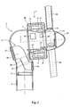
- FIG. 1 shows a cross section through a machine housing 4 of a windmill.
- the machine housing 4 is positioned on a mast 1 by means of a bearing 2.
- the machine housing 4 comprises a generator 7 which is mounted around a conical bush 5.
- a stator 9 On the conical bush 5 are mounted a stator 9 and a main bearing 11 which can rotate about an axis of rotation 3.
- a rotor 8, which is arranged on the outside of the stator 9, is attached to the rotating part of the main bearing 11.
- the outer circumference of the generator 7 is covered by a generator cap 6 which rotates with the rotor 8, thus forming a generator chamber 46.
- a vane support 12 to which three vanes 10 are attached, is likewise attached to the rotating part of the main bearing 11, which vanes 10 are provided with a vane adjustment mechanism (not shown).
- a slip ring holder 14 with slip rings To provide current to the rotor 8 and the vane adjustment mechanisms, there is a slip ring holder 14 with slip rings.
- the front side of the vane support 12 is protected by a nose cap 13.
- a platform 15 is arranged inside the machine housing 4 at the location of the conical bush 5, for operating staff.
- the machine housing 4 also accommodates an air unit 16, a cooling unit 17 and a lubrication unit 18.
- the air unit 16 is responsible for feeding air to the generator chamber 46, this air preferably being dried in order to prevent moisture from reaching the windings of the generator 7.
- the cooling unit 17 ensures that cooling liquid is circulated through the stator 9 of the generator, with the result that heat is dissipated from the generator 7. Considerable amounts of heat are developed in the stator 9 of the generator, which heat has to be dissipated immediately.
- the cooling unit 17 accommodates a heat exchanger 49 which is held in an air channel 56.
- the air channel 56 runs from a cooling-air inlet 54, which is arranged on the windward side of the machine housing 4, to a cooling-air outlet 57, which is positioned on the leeward side of the machine housing 4.
- the air channel 56 is a more or less closed channel, so that the cooling air, which may be salty and moist, does not enter the machine housing 4.
- the air channel 56 accommodates a fan 55, so that the dimensions of the air channel 56 and the heat exchanger 49 can be kept smaller while retaining the same cooling capacity. If appropriate, heat can be fed to the circulating cooling liquid during or after a prolonged standstill period, for example, as a result of the absence of wind, in order to keep warm or heat the windings of the stator 9, so that condensation is not formed or disappears.
- the lubrication unit 18 ensures that the main bearing 11 is suitably lubricated.
- the machine housing 4 contains various control and safety units which are not described in more detail, for example for controlling the adjustment of the vanes and for controlling the abovementioned units. Additionally, there is a brake (not shown) and, if appropriate, a blocking pin for stopping movement of the vanes 10 of the windmill during maintenance work.
- the mast 1 is approximately 70 metres high and has a diameter of 2 metres.
- the diameter of the vanes 10 is 70 metres, the diameter of the main bearing 11 is approximately 1800 millimetres and the diameter of the generator is 3800 millimetres.
- the rated output generated by the generator 9 is 1500 kilowatts at a rotational speed of the rotor of 18 revolutions per minute and 2000 kilowatts at 24 revolutions per minute.
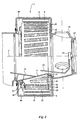
- FIG. 2 shows the generator 7.
- the bottom half of the figure shows the stator 9 in cross section.
- a support ring 22 with support plates 21 is secured around the conical bush 5.
- the top half of the figure shows a view of the outside of the stator coil 20, from which it can be seen that the stator poles 19 form an angle of approximately 5 degrees with the axis of rotation 3. On account of this angle, the stator poles 19 also form an angle with the magnets of the rotor 8 which are positioned parallel to the axis of rotation 3. This results in the generator running quietly.
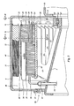
- FIGS 3 and 4 show a more detailed view of the generator 7, Figure 3 showing the cross sections IIIA and IIIB from Figure 4, and Figure 4 showing the cross section IVA and the view IVB from Figure 3.
- the stator core 23 is arranged around the support ring 22, the stator core 23 being provided with stator poles 19 and winding slots 30 between them. The windings running through the winding slots 30 together form the stator coil 20.
- the stator core 23 is composed of plates which are clamped between clamping plates 29 by tension rods 34. Cooling lines 29 run through the stator core 23, and are connected to an inlet line 24 and an outlet line via a manifold.
- Magnet cores 33 are attached to the generator cap 6 in a known way.
- a coil 31 which, during use, is energised in a known way by a field current, so that when the rotor 8 rotates, changing magnetic fields are generated in an air gap 32 between the stator poles 19 and the magnet cores 33, with the result that electric voltage and an electric current is generated in the stator coil 20.
- heat is developed in the stator 9, and this heat has to be dissipated.
- the temperature in the windings is measured using a temperature sensor 44. If the temperature is too high, for example if it reaches above 40° Celsius, the cooling unit 17 is switched on.
- the cooling unit 17 is provided, for example, with a controller for keeping the temperature of the stator at a constant level. As a result, the temperature of the stator coil 20 remains low, with the result that the resistance in the wires of the windings does not increase and there is no adverse effect on the efficiency.
- the heat which is generated in the rotating magnet coils 31 and the magnet core 33 is dissipated via the magnet core 33 to the generator cap 6 and, from there, to atmosphere.
- the temperature in the stator 9 being held at 40° Celsius, the temperature of the space enclosed by the stator also does not become any warmer, and the temperature of the equipment inside the machine housing 4 and of the main bearing 11 remains sufficiently low, so that there is no need to provide any additional cooling for these components.
- the rotor has coils 31 which are easy to heat electrically as a result of current being passed through the coils 31, generation of current in the stator 9 being prevented by, for example, energizing the coils 31 with AC current.
- An additional advantage of the uniform heating of the stator 9 and of the stator 9 being held at a constant temperature is that it maintains the same temperature all the way around and therefore expands uniformly and to a limited extent all the way around as a result of the temperature being controlled within tight limits.
- the air gap 32 will remain the same all the way around and does not become too small in certain areas through local expansion.
- the air gap 32 can be kept small, which has a beneficial effect on the efficiency of the generator 7.
- the risk of condensation on the stator coil 20 is reduced further by ensuring that the generator chamber 46 contains only dry air, which is useful in particular if the windmill is positioned, for example, near or in the sea.
- the main bearing 11 is provided in a known way with seals 45, and a seal 26 is positioned between the rotating generator cap 6 and the stationary conical ring 5, and all other openings in the generator chamber 46 are sealed.
- the seal 26 is provided with a dust cap 27, so that the rubber of the seal is protected from the effects of sun and other influences from the weather.
- the air unit 16 provides a possibly limited superatmospheric pressure in the generator chamber 46 by supplying air from the machine housing 4, which air is as dry as possible and is preferably dried even further using an air dryer. If appropriate, the air unit 16 is designed in such a manner that air is sucked out of the generator chamber 46. This air is then mixed in the air unit 16 with a limited amount of air from the outside or from out of the machine housing 4 and is then dried and returned to the generator chamber 46. If appropriate, the air unit 16 is provided with switching means, so that the air unit is only switched on when the windmill is at a standstill.
- sensors (not shown) to be arranged in the generator chamber 46, which can be used to measure the dew point of the air. If the air approaches the dew point, for example as a result of cooling, the air unit 16 switches on, so that condensation is prevented.
- the exemplary embodiment describes a generator 7 in which the air gap 32 is a round cylinder. It is also possible in a similar way to make a generator in which the air gap 32 is conical, so that the generator 7 better follows the shape of the conical bush 5, and, if appropriate, weight may be saved.
- the generator 7 illustrated is designed with forty-eight stator poles 19 and forty-eight magnet coils 31. Naturally, the generator may also be designed differently, for example with permanent magnets instead of the rotor 8 shown here, in which case features may be provided in the form of, for example, a displaceable stainless steel bush for interrupting the magnetic field lines when the windmill is switched off.
- the main bearing 11 For the windmill to operate without problems, it is important that the main bearing 11 should be continuously provided with lubricant.
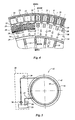
- a lubrication unit 18 is available, the action of which is shown in Figure 5.
- the main bearing 11 has an outer ring 41, an inner ring 43, a race 42 and seals 45 (cf. Figure 3).
- a feed line 40 opens out into the race 42, and half-way between the bottom and the centre of the main bearing 11 there is a return line 37 connected to the race 42.
- a pump 36 is used to pump oil out of a buffer vessel 35 into the feed line 40, a pressure and/or flow rate sensor 39 being used to monitor whether oil is being pumped. Oil which has been pumped into the race 42 flows back into the buffer vessel 35.
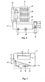
- FIG. 6 diagrammatically depicts the system for controlling the temperature of the stator 9, known components of a circulation system of this type, including a liquid reservoir, sensors, thermostatic valves, shut-off valves and other control means not being shown in this figure. Since this system is essential for the generation of electricity, where necessary the various components are in duplicate, so that the windmill is prevented from shutting down if a component fails.
- a circulation pump 47 liquid is pumped through the feed line 24 and the manifold 25 to the cooling lines 28.
- the liquid emerging from the stator 9 is passed into a heat exchanger 49 where it is cooled by air circulation.
- the heat exchanger 49 is positioned in the closed air channel 56 through which outside air can flow.
- the flow of the outside air through the heat exchanger 49 takes place as a result of the wind which blows on to the cooling air outlet 54, if appropriate with the assistance of thermal circulation as a result of heated air rising towards the cooling air outlet 57, which is at a higher level than the cooling air inlet 54.
- the air channel 56 contains a fan which, for example, is switched on when additional cooling is required.
- the heat exchanger 49 may for example, also be designed as part of the wall of the machine housing 4, the heat being dissipated by air which flows along the outside. If appropriate, the circulating liquid is heated in a heater arrangement 48, so that the stator 9 can be heated. To provide reliable operation, the circulation pump 47 and the heat exchanger 49 may be provided in duplicate.
- the air channel 56 may also be designed differently, as shown in Figure 8.
- the air channel 56 is formed by the conical bush 5 and the support ring 22, which is then widened to as far as the front and rear sides of the generator cap 6.
- the generator cap 6 On the front side, the generator cap 6 is provided with cooling air inlets 54 and on the rear side there are openings as cooling air outlets 57. Means which are not shown are also provided for discharging the rain which blows into the chamber.
- FIG. 7 diagrammatically depicts the way in which the means for maintaining a superatmospheric pressure in the generator chamber 46 operates.
- the generator chamber 46 is more or less airtight and air which is blown in by means of a fan 50 via an air inlet 52 can only emerge via an air outlet 53, which air outlet 53 is situated, for example, at the location of the seal 26.
- an air dryer 51 it is preferable to use an air dryer 51, so that the moisture content of the air in the generator chamber 46 remains low.
- the air unit 16 is designed in such a manner that the amount of air present in the generator chamber 46 is sucked in by the fan 50 at the same time as a small amount of outside air which is required in order to maintain a superatmospheric pressure in the generator chamber 46.
- the air which has been sucked in is dried in the air dryer 51 and is introduced into the generator chamber 46.
- FIG 9 shows a second embodiment of the generator of the windmill shown in Figure 1.
- the main bearing 11 is coupled to the machine housing 4 by the conical bush 5.
- the vane support 12 is coupled to the outer ring of the main bearing 11.
- the generator is designed with the rotor inside the stator.
- a rotor support ring 67 is attached to the outer ring of the main bearing 11.
- a generator inner ring 66 is secured around the rotor support ring 67.
- Rotor poles 64 are attached to the generator inner ring 66.
- the rotor poles 64 are in this case designed as permanent magnets.
- a generator rear wall 65 is also attached to the machine housing 4.
- the generator rear wall 65 supports a generator outer ring 61.
- the generator outer ring 61 is provided with a generator front wall 60 which adjoins the vane support 12.
- a seal 68 is positioned between the stationary generator front wall 60 and the rotating vane support 12.
- the seal 68 is designed in such a manner that it is impossible for any outside air to enter, so that the air in the generator chamber 46 can be dried in the manner described above and can be kept at a slight superatmospheric pressure.
- the seal 68 is accessible from the generator chamber 46, so that it is easy to carry out maintenance work thereon.
- Stator poles 63 are arranged on the inside of the generator outer ring 61. To dissipate the heat generated in the generator poles 63, cooling ribs 62 are arranged on the outside of the generator outer ring 61. To ensure that the stator poles 63 are at the same temperature all the way around, the stator poles 63 are provided with a liquid circulation system, in the manner described above. This liquid circulation system may be permanently switched on or may be switched on only when temperature differences between the stator poles 63 are measured.
- stator prevents the stator from reaching a temperature which is not uniform all the way around, for example as a result of insolation or as a result of differences in the dissipation of heat via the cooling ribs 62, which are caused by differences in flow around the machine housing 4.
Landscapes
- Engineering & Computer Science (AREA)
- Power Engineering (AREA)
- Life Sciences & Earth Sciences (AREA)
- Sustainable Energy (AREA)
- Sustainable Development (AREA)
- Combustion & Propulsion (AREA)
- Chemical & Material Sciences (AREA)
- Mechanical Engineering (AREA)
- General Engineering & Computer Science (AREA)
- Manufacturing & Machinery (AREA)
- Physics & Mathematics (AREA)
- Thermal Sciences (AREA)
- Motor Or Generator Cooling System (AREA)
- Wind Motors (AREA)
- Motor Or Generator Frames (AREA)
Priority Applications (1)
| Application Number | Priority Date | Filing Date | Title |
|---|---|---|---|
| EP06115518.0A EP1710432B1 (en) | 2000-09-25 | 2000-09-25 | Wind power generator |
Applications Claiming Priority (3)
| Application Number | Priority Date | Filing Date | Title |
|---|---|---|---|
| NL1013129A NL1013129C2 (nl) | 1999-09-24 | 1999-09-24 | Windmolen. |
| NL1013129 | 1999-09-24 | ||
| PCT/NL2000/000686 WO2001021956A1 (en) | 1999-09-24 | 2000-09-25 | Wind power generator |
Related Child Applications (1)
| Application Number | Title | Priority Date | Filing Date |
|---|---|---|---|
| EP06115518.0A Division EP1710432B1 (en) | 2000-09-25 | 2000-09-25 | Wind power generator |
Publications (2)
| Publication Number | Publication Date |
|---|---|
| EP1218638A1 EP1218638A1 (en) | 2002-07-03 |
| EP1218638B1 true EP1218638B1 (en) | 2006-08-09 |
Family
ID=19769929
Family Applications (1)
| Application Number | Title | Priority Date | Filing Date |
|---|---|---|---|
| EP00970307A Expired - Lifetime EP1218638B1 (en) | 1999-09-24 | 2000-09-25 | Wind power generator |
Country Status (7)
| Country | Link |
|---|---|
| US (2) | US6774504B1 (enExample) |
| EP (1) | EP1218638B1 (enExample) |
| JP (1) | JP3909516B2 (enExample) |
| AT (1) | ATE335926T1 (enExample) |
| DE (1) | DE60029977T2 (enExample) |
| NL (1) | NL1013129C2 (enExample) |
| WO (1) | WO2001021956A1 (enExample) |
Cited By (1)
| Publication number | Priority date | Publication date | Assignee | Title |
|---|---|---|---|---|
| US9784247B2 (en) | 2014-04-25 | 2017-10-10 | Siemens Aktiengesellschaft | Apparatus for dampening of acoustic noise generated by air-cooling of at least one wind turbine component provided with the nacelle of a wind turbine |
Families Citing this family (137)
| Publication number | Priority date | Publication date | Assignee | Title |
|---|---|---|---|---|
| BR9915707A (pt) | 1998-11-26 | 2001-08-14 | Aloys Wobben | Instalação de energia eólica |
| NL1013129C2 (nl) * | 1999-09-24 | 2001-03-27 | Lagerwey Windturbine B V | Windmolen. |
| BR0110792B1 (pt) * | 2000-05-12 | 2012-10-30 | instalação de energia eólica e processo para deslocar uma casa de máquinas de tal instalação. | |
| DE10119625B4 (de) * | 2001-04-20 | 2004-04-08 | Wobben, Aloys, Dipl.-Ing. | Verfahren zur Steuerung einer Windenergieanlage |
| DE10124268B4 (de) * | 2001-05-18 | 2006-02-09 | Wobben, Aloys, Dipl.-Ing. | Generatorkühlung |
| DE10139556A1 (de) * | 2001-08-10 | 2003-02-27 | Aloys Wobben | Einrichtung zur Entfeuchtung eines gasförmigen Mediums und Windenergieanlage mit einer solchen Einrichtung |
| DE10141667A1 (de) * | 2001-08-25 | 2003-03-13 | Aloys Wobben | Vorrichtung zum Verdrehen von zwei Bauteilen gegeneinander |
| ITBZ20010043A1 (it) * | 2001-09-13 | 2003-03-13 | High Technology Invest Bv | Generatore elettrico azionato da energia eolica. |
| GB2382117B (en) * | 2001-10-05 | 2005-07-20 | Hansen Transmissions Int | Wind turbine gear unit lubrication |
| WO2003036083A1 (en) * | 2001-10-25 | 2003-05-01 | Nsk Ltd. | Wind power generator |
| EP1340910A1 (en) * | 2002-02-28 | 2003-09-03 | Enel Green Power S.p.A. | Aerogenerator with axial flux permanent magnets and regulation thereof |
| DE10231948A1 (de) | 2002-07-15 | 2004-01-29 | Ge Wind Energy Gmbh | Windenergieanlage und Lageranordnung dafür |
| DE10233947A1 (de) † | 2002-07-25 | 2004-02-12 | Siemens Ag | Windkraftanlage |
| WO2004017494A1 (de) * | 2002-08-16 | 2004-02-26 | Alstom Technology Ltd | Dynamoelektrischer generator |
| US20050172651A1 (en) * | 2002-08-16 | 2005-08-11 | Alstom Technology Ltd | Dynamoelectrical generator |
| DE10245103A1 (de) * | 2002-09-27 | 2004-04-08 | General Electric Co. | Schaltschrank für eine Windenergieanlage und Verfahren zum Betreiben einer Windenergieanlage |
| ES2233146B1 (es) * | 2002-11-21 | 2006-06-01 | Manuel Torres Martinez | Alternador multipolar para aerogeneradores. |
| US6952058B2 (en) * | 2003-02-20 | 2005-10-04 | Wecs, Inc. | Wind energy conversion system |
| US7431567B1 (en) | 2003-05-30 | 2008-10-07 | Northern Power Systems Inc. | Wind turbine having a direct-drive drivetrain |
| JP4031747B2 (ja) | 2003-09-30 | 2008-01-09 | 三菱重工業株式会社 | 風力発電用風車 |
| JP4237075B2 (ja) * | 2004-02-17 | 2009-03-11 | 三菱電機株式会社 | 回転電機 |
| DE102004018758A1 (de) | 2004-04-16 | 2005-11-03 | Klinger, Friedrich, Prof. Dr.-Ing. | Turmkopf einer Windenergieanlage |
| US7075192B2 (en) | 2004-04-19 | 2006-07-11 | Northern Power Systems, Inc. | Direct drive wind turbine |
| US7154191B2 (en) | 2004-06-30 | 2006-12-26 | General Electric Company | Electrical machine with double-sided rotor |
| US7154193B2 (en) | 2004-09-27 | 2006-12-26 | General Electric Company | Electrical machine with double-sided stator |
| US7154192B2 (en) | 2004-09-27 | 2006-12-26 | General Electric Company | Electrical machine with double-sided lamination stack |
| US7548008B2 (en) | 2004-09-27 | 2009-06-16 | General Electric Company | Electrical machine with double-sided lamination stack |
| US7839048B2 (en) | 2004-09-27 | 2010-11-23 | General Electric Company | Electrical machine with double-sided stator |
| US7692357B2 (en) | 2004-12-16 | 2010-04-06 | General Electric Company | Electrical machines and assemblies including a yokeless stator with modular lamination stacks |
| US7391128B2 (en) * | 2004-12-30 | 2008-06-24 | Rozlev Corp., Llc | Wind generator system using attractive magnetic forces to reduce the load on the bearings |
| US7180204B2 (en) * | 2005-01-07 | 2007-02-20 | General Electric Company | Method and apparatus for wind turbine air gap control |
| EP1902216B1 (en) * | 2005-07-12 | 2011-10-05 | Hamilton Sundstrand Corporation | Wind-turbine with load-carrying skin |
| US7215038B2 (en) * | 2005-07-26 | 2007-05-08 | Bacon C Richard | Wind wheel and electricity generator using same |
| US7443066B2 (en) * | 2005-07-29 | 2008-10-28 | General Electric Company | Methods and apparatus for cooling wind turbine generators |
| AR052000A1 (es) * | 2005-11-07 | 2007-02-28 | Metalurgicas Pescar Industrias | Generador eolico integrado de potencia |
| US7528497B2 (en) | 2006-07-11 | 2009-05-05 | Hamilton Sundstrand Corporation | Wind-turbine with load-carrying skin |
| PL1925820T3 (pl) * | 2006-11-23 | 2011-04-29 | Stx Heavy Ind Co Ltd | Łożysko główne turbiny wiatrowej |
| ES2484440T3 (es) | 2006-11-28 | 2014-08-11 | Alstom Renovables España, S.L. | Procedimiento de lubricación dinámica de un cojinete de inclinación de las palas de un aerogenerador |
| RU2324278C1 (ru) * | 2006-12-11 | 2008-05-10 | Государственное образовательное учреждение высшего профессионального образования "Иркутский государственный университет путей сообщения (ИрГУПС) | Способ сушки изоляции электрических машин |
| US8262338B2 (en) | 2007-01-11 | 2012-09-11 | Cassidy Joe C | Vertical axis dual vortex downwind inward flow impulse wind turbine |
| WO2008092449A2 (en) * | 2007-01-31 | 2008-08-07 | Vestas Wind Systems A/S | Wind energy converter with dehumidifier |
| US7821164B2 (en) | 2007-02-15 | 2010-10-26 | General Electric Company | Method and apparatus for a superconducting generator driven by wind turbine |
| DE102007042338A1 (de) * | 2007-09-06 | 2009-03-12 | Siemens Ag | Windkraftanlage mit Wärmetauschersystem |
| NL2001190C1 (nl) * | 2008-01-16 | 2009-07-20 | Lagerwey Wind B V | Generator voor een direct aangedreven windturbine. |
| EP2096303A1 (en) * | 2008-02-29 | 2009-09-02 | Darwind Holding B.V. | Windturbine comprising a bearing seal |
| EP2255088B1 (de) * | 2008-03-20 | 2011-11-09 | Powerwind Gmbh | Windenergieanlage und verfahren zum betreiben einer windenergieanlage |
| EP2108832B1 (en) * | 2008-04-10 | 2015-12-02 | Siemens Aktiengesellschaft | Generator and wind turbine |
| DK2109206T3 (da) | 2008-04-10 | 2013-06-17 | Siemens Ag | Generator med en stator omfattende kølekanaler samt fremgangsmåde til køling af en lamineret stator af en generator |
| DE102008019271A1 (de) * | 2008-04-16 | 2009-10-22 | Kenersys Gmbh | Windkraftanlage mit verbesserter Kühlluftführung |
| ITMI20081122A1 (it) | 2008-06-19 | 2009-12-20 | Rolic Invest Sarl | Generatore eolico provvisto di un impianto di raffreddamento |
| DK2143942T3 (en) * | 2008-07-07 | 2016-03-29 | Siemens Ag | Windmill |
| DK2143944T3 (en) * | 2008-07-07 | 2019-01-14 | Siemens Ag | Windmill |
| EP2143943A1 (en) * | 2008-07-09 | 2010-01-13 | Greenergy India Private Limited | Wind turbine |
| WO2010018630A1 (ja) * | 2008-08-14 | 2010-02-18 | 三菱重工業株式会社 | 風力発電装置 |
| KR100987571B1 (ko) * | 2008-09-01 | 2010-10-12 | 두산중공업 주식회사 | 풍력 터빈 발전기의 냉각 시스템 |
| KR101021333B1 (ko) | 2008-09-01 | 2011-03-14 | 두산중공업 주식회사 | 풍력터빈의 나셀 냉각 시스템 |
| EP2164154A1 (en) | 2008-09-15 | 2010-03-17 | Siemens Aktiengesellschaft | Stator arrangement, generator and wind turbine |
| DE102008050848A1 (de) † | 2008-10-08 | 2010-04-15 | Wobben, Aloys | Ringgenerator |
| EP2182570A1 (en) * | 2008-10-28 | 2010-05-05 | Siemens Aktiengesellschaft | Arrangement for cooling of an electrical machine |
| EP2182618B1 (en) * | 2008-10-28 | 2012-10-17 | Siemens Aktiengesellschaft | Arrangement for cooling of an electrical machine |
| DK2182619T3 (da) | 2008-10-28 | 2012-11-19 | Siemens Ag | Anordning til afkøling af en elektrisk maskine |
| DK2182617T3 (da) * | 2008-10-28 | 2013-01-02 | Siemens Ag | Anordning til køling af en elektrisk maskine |
| IT1391939B1 (it) * | 2008-11-12 | 2012-02-02 | Rolic Invest Sarl | Generatore eolico |
| DE102009017325A1 (de) * | 2009-04-16 | 2010-10-21 | Avantis Ltd. | Generatorkühlanordnung einer Windenergieanlage |
| IT1393707B1 (it) | 2009-04-29 | 2012-05-08 | Rolic Invest Sarl | Impianto eolico per la generazione di energia elettrica |
| DE102009032885A1 (de) * | 2009-07-13 | 2011-02-03 | Siemens Aktiengesellschaft | Ringförmiger Rotor für eine elektrische Maschine |
| US8043012B2 (en) | 2009-09-30 | 2011-10-25 | General Electric Company | Seal arrangement and a brush seal for a wind turbine |
| EP2320080A1 (en) * | 2009-11-06 | 2011-05-11 | Siemens Aktiengesellschaft | Arrangement for cooling of an electrical generator |
| DE102010000756A1 (de) * | 2010-01-08 | 2011-07-14 | Wobben, Aloys, 26607 | Windenergieanlage |
| KR101729910B1 (ko) * | 2010-01-11 | 2017-05-11 | 지멘스 악티엔게젤샤프트 | 냉각 시스템을 구비한 직접 구동 윈드 터빈 |
| IT1399263B1 (it) | 2010-01-29 | 2013-04-11 | Trevi Energy S P A | Turbina eolica monocuscinetto con generatore elettrico a flusso radiale e statore esterno. |
| IT1398060B1 (it) * | 2010-02-04 | 2013-02-07 | Wilic Sarl | Impianto e metodo di raffreddamento di un generatore elettrico di un aerogeneratore, e aerogeneratore comprendente tale impianto di raffreddamento |
| JP5204216B2 (ja) * | 2010-02-08 | 2013-06-05 | 三菱重工業株式会社 | 風力発電装置 |
| IT1399201B1 (it) | 2010-03-30 | 2013-04-11 | Wilic Sarl | Aerogeneratore e metodo di rimozione di un cuscinetto da un aerogeneratore |
| EP2378631A1 (en) | 2010-04-13 | 2011-10-19 | Siemens Aktiengesellschaft | Stator-arrangement |
| CN101814793B (zh) * | 2010-04-16 | 2012-04-18 | 湘电风能有限公司 | 一种自然风冷直驱同步风力发电机 |
| WO2011133024A2 (en) * | 2010-04-19 | 2011-10-27 | Synervisie B.V. | Highly integrated energy conversion system for wind, tidal or hydro turbines |
| IT1399511B1 (it) | 2010-04-22 | 2013-04-19 | Wilic Sarl | Generatore elettrico per un aerogeneratore e aerogeneratore equipaggiato con tale generatore elettrico |
| US20110133476A1 (en) * | 2010-04-29 | 2011-06-09 | Jacob Johannes Nies | Rotor support device and method for accessing a drive train of a wind turbine |
| JP5449060B2 (ja) * | 2010-06-30 | 2014-03-19 | 三菱重工業株式会社 | 風力発電装置 |
| EP2410636A1 (en) | 2010-07-23 | 2012-01-25 | Ewt Ip B.V. | Lip seal for a generator |
| EP2413475A1 (en) | 2010-07-30 | 2012-02-01 | Ewt Ip B.V. | Cooling system for generator |
| ES2553277T3 (es) * | 2010-08-31 | 2015-12-07 | Vestas Wind Systems A/S | Turbina eólica con un sistema de transferencia de calor |
| US8789274B2 (en) | 2010-09-23 | 2014-07-29 | Northern Power Systems, Inc. | Method and system for servicing a horizontal-axis wind power unit |
| US8816546B2 (en) * | 2010-09-23 | 2014-08-26 | Northern Power Systems, Inc. | Electromagnetic rotary machines having modular active-coil portions and modules for such machines |
| US9359994B2 (en) | 2010-09-23 | 2016-06-07 | Northern Power Systems, Inc. | Module-handling tool for installing/removing modules into/from an electromagnetic rotary machine having a modularized active portion |
| US8912704B2 (en) | 2010-09-23 | 2014-12-16 | Northern Power Systems, Inc. | Sectionalized electromechanical machines having low torque ripple and low cogging torque characteristics |
| US9281731B2 (en) | 2010-09-23 | 2016-03-08 | Northem Power Systems, Inc. | Method for maintaining a machine having a rotor and a stator |
| JP5550508B2 (ja) * | 2010-09-28 | 2014-07-16 | 株式会社日立製作所 | 風力発電装置 |
| CN101958599B (zh) * | 2010-09-29 | 2012-05-23 | 华小平 | 风力发电机散热结构 |
| DK2442060T3 (da) * | 2010-10-13 | 2014-01-06 | Siemens Ag | Generator, især til en vindmølle |
| NZ609843A (en) | 2010-11-04 | 2015-05-29 | Wobben Properties Gmbh | Wind energy installation having a synchronous generator, and slowly rotating synchronous generator |
| JP5724301B2 (ja) * | 2010-11-04 | 2015-05-27 | 株式会社明電舎 | 発電機の冷却構造 |
| EP2477311B1 (en) * | 2011-01-18 | 2014-03-05 | Siemens Aktiengesellschaft | Generator, in particular for a wind turbine |
| WO2012107192A2 (en) * | 2011-02-07 | 2012-08-16 | Xemc Vwec B.V. | Direct drive wind turbine with slip ring |
| JP5808548B2 (ja) * | 2011-02-23 | 2015-11-10 | Ntn株式会社 | 転がり軸受および風力発電装置 |
| EP2492503B1 (en) * | 2011-02-25 | 2018-01-03 | Siemens Aktiengesellschaft | A wind turbine with a generator |
| ITMI20110375A1 (it) | 2011-03-10 | 2012-09-11 | Wilic Sarl | Turbina eolica |
| ITMI20110377A1 (it) | 2011-03-10 | 2012-09-11 | Wilic Sarl | Macchina elettrica rotante per aerogeneratore |
| ITMI20110378A1 (it) | 2011-03-10 | 2012-09-11 | Wilic Sarl | Macchina elettrica rotante per aerogeneratore |
| DE102011006680A1 (de) * | 2011-04-01 | 2012-10-04 | Aloys Wobben | Blechpaketanordnung |
| DE102011006681A1 (de) * | 2011-04-01 | 2012-10-04 | Aloys Wobben | Polschuh |
| EP2512007B1 (en) * | 2011-04-15 | 2019-06-05 | Siemens Gamesa Renewable Energy A/S | Access means for an electrical machine |
| EP2520797B1 (en) * | 2011-05-03 | 2015-10-21 | Siemens Aktiengesellschaft | Direct drive wind turbine with a thermal control system |
| CA2856875C (en) * | 2011-12-21 | 2017-11-07 | Wobben Properties Gmbh | Wind turbine nacelle |
| DK2617995T4 (en) * | 2012-01-20 | 2018-04-23 | Siemens Ag | Windmill |
| JP5703397B2 (ja) * | 2012-01-23 | 2015-04-15 | 株式会社日立製作所 | 風力発電設備 |
| DE102012201088A1 (de) * | 2012-01-25 | 2013-07-25 | Wobben Properties Gmbh | Verfahren und Vorrichtung zum Montieren einer Rotornabe einer Windenergieanlage |
| EP2816225B1 (en) * | 2012-02-17 | 2016-11-30 | ADWEN Offshore, S.L. | Direct-drive wind turbine |
| DE102012208372A1 (de) * | 2012-05-18 | 2013-11-21 | Siemens Aktiengesellschaft | Windenergieanlage |
| DE102012213911A1 (de) * | 2012-08-06 | 2014-02-06 | Siemens Aktiengesellschaft | Windenergieanlage |
| US20140152631A1 (en) | 2012-12-05 | 2014-06-05 | Braeburn Systems Llc | Climate control panel with non-planar display |
| AU2014257722A1 (en) * | 2013-04-23 | 2015-12-03 | youWINenergy GmbH | Wind turbine architecture |
| DK2806542T3 (en) | 2013-05-22 | 2016-12-19 | Siemens Ag | Airflow Control Device |
| JP2015068186A (ja) * | 2013-09-27 | 2015-04-13 | 株式会社安川電機 | 風力発電システム、風力発電システムの制御方法、回転電機システムおよび回転電機の制御装置 |
| EP2902619B1 (en) | 2014-01-29 | 2018-01-17 | Siemens Aktiengesellschaft | Cooling arrangement for a direct drive wind turbine |
| CA2894359C (en) | 2014-06-16 | 2022-07-05 | Braeburn Systems Llc | Graphical highlight for programming a control |
| CA2910090C (en) | 2014-10-22 | 2023-07-25 | Braeburn Systems Llc | Thermostat code input system and method therefor using ssid |
| US10430056B2 (en) | 2014-10-30 | 2019-10-01 | Braeburn Systems Llc | Quick edit system for programming a thermostat |
| US10055323B2 (en) | 2014-10-30 | 2018-08-21 | Braeburn Systems Llc | System and method for monitoring building environmental data |
| CN104600886B (zh) * | 2015-01-27 | 2017-01-25 | 新疆金风科技股份有限公司 | 永磁直驱风力发电机、系统及其定子 |
| CA2920281C (en) | 2015-02-10 | 2021-08-03 | Daniel S. Poplawski | Thermostat configuration duplication system |
| CN104810997B (zh) * | 2015-04-15 | 2017-03-01 | 新疆金风科技股份有限公司 | 永磁直驱风力发电机系统及其密封协同干燥控制方法 |
| CN104810942B (zh) * | 2015-04-15 | 2017-03-01 | 新疆金风科技股份有限公司 | 永磁直驱风力发电机、系统及其定子 |
| GB201509064D0 (en) | 2015-05-27 | 2015-07-08 | Net Defence Ltd | Control and monitoring system and method |
| US10317867B2 (en) | 2016-02-26 | 2019-06-11 | Braeburn Systems Llc | Thermostat update and copy methods and systems |
| US10317919B2 (en) | 2016-06-15 | 2019-06-11 | Braeburn Systems Llc | Tamper resistant thermostat having hidden limit adjustment capabilities |
| MX2017011987A (es) | 2016-09-19 | 2018-09-26 | Braeburn Systems Llc | Sistema de gestion de control que tiene calendario perpetuo con excepciones. |
| DE102017123836A1 (de) * | 2017-10-13 | 2019-04-18 | Wobben Properties Gmbh | Synchrongenerator für eine Windenergieanlage und Windenergieanlage |
| US10921008B1 (en) | 2018-06-11 | 2021-02-16 | Braeburn Systems Llc | Indoor comfort control system and method with multi-party access |
| RU2690669C1 (ru) * | 2018-09-17 | 2019-06-05 | Общество с ограниченной ответственностью "Уральские локомотивы" | Способ сушки изоляции тяговых электродвигателей электровоза |
| US10802513B1 (en) | 2019-05-09 | 2020-10-13 | Braeburn Systems Llc | Comfort control system with hierarchical switching mechanisms |
| CN112664392B (zh) | 2019-10-15 | 2025-09-05 | 通用电气可再生能源西班牙有限公司 | 用于在延长的维护期间锁定风力涡轮转子的系统和方法 |
| CN112780493B (zh) * | 2019-11-06 | 2023-04-21 | 国家电投集团科学技术研究院有限公司 | 直驱风力发电装置 |
| RU2742653C1 (ru) * | 2020-08-13 | 2021-02-09 | Общество с ограниченной ответственностью "Уральские локомотивы" | Способ сушки изоляции тяговых электродвигателей электровоза |
| US11925260B1 (en) | 2021-10-19 | 2024-03-12 | Braeburn Systems Llc | Thermostat housing assembly and methods |
| EP4296508A1 (en) | 2022-06-20 | 2023-12-27 | Siemens Gamesa Renewable Energy A/S | Fluid bearing comprising a brake assembly |
Family Cites Families (22)
| Publication number | Priority date | Publication date | Assignee | Title |
|---|---|---|---|---|
| GB2050525A (en) * | 1979-03-13 | 1981-01-07 | Plot Ltd C | A Generator |
| US4421967A (en) * | 1980-07-21 | 1983-12-20 | Vs Systems, Inc. | Windmill driven eddy current heater |
| US4765066A (en) * | 1987-08-19 | 1988-08-23 | Vbe Inc. | Microwave clothes dryer |
| NL8902534A (nl) * | 1989-10-12 | 1991-05-01 | Holec Projects Bv | Windturbine. |
| US5117143A (en) * | 1991-03-22 | 1992-05-26 | Electric Motors And Specialities, Inc. | Anti-windmilling motor |
| GB9112059D0 (en) * | 1991-06-05 | 1991-07-24 | Jestar Ltd | Electrical machines |
| DE4402184C2 (de) * | 1994-01-26 | 1995-11-23 | Friedrich Prof Dr Ing Klinger | Vielpol-Synchrongenerator für getriebelose Horizontalachsen-Windkraftanlagen mit Nennleistungen bis zu mehreren Megawatt |
| KR0183630B1 (ko) * | 1995-05-15 | 1999-03-20 | 윤종용 | 형광체 건조장치 및 건조방법 |
| US5605045A (en) * | 1995-09-18 | 1997-02-25 | Turbodyne Systems, Inc. | Turbocharging system with integral assisting electric motor and cooling system therefor |
| DE19636591C2 (de) * | 1996-09-10 | 1999-12-09 | Friedrich Klinger | Synchrongenerator für einen getriebelosen Windenergiekonverter |
| US5731649A (en) * | 1996-12-27 | 1998-03-24 | Caama+E,Otl N+Ee O; Ramon A. | Electric motor or generator |
| FR2760492B1 (fr) * | 1997-03-10 | 2001-11-09 | Jeumont Ind | Systeme de production d'energie electrique associe a une eolienne |
| US6132186A (en) * | 1997-08-06 | 2000-10-17 | Shurflo Pump Manufacturing Co. | Impeller pump driven by a dynamo electric machine having a stator comprised of a mass of metal particles |
| US6034465A (en) * | 1997-08-06 | 2000-03-07 | Shurfle Pump Manufacturing Co. | Pump driven by brushless motor |
| EP1038103A1 (de) * | 1997-12-08 | 2000-09-27 | Siemens Aktiengesellschaft | Windkraftanlage und verfahren zur kühlung eines generators einer windkraftanlage |
| DE19801803A1 (de) * | 1998-01-19 | 1999-04-29 | Siemens Ag | Elektrische Rotationsmaschine und Verfahren zur Übertragung elektrischer Leistung |
| DE19802574A1 (de) * | 1998-01-23 | 1999-03-11 | Siemens Ag | Windkraftanlage und Verfahren zum Betrieb einer Windkraftanlage |
| JPH11299197A (ja) | 1998-04-14 | 1999-10-29 | Suiden Co Ltd | 風力発電機 |
| US6259165B1 (en) * | 1999-04-23 | 2001-07-10 | Power Tube, Inc. | Power generating device and method |
| NL1013129C2 (nl) * | 1999-09-24 | 2001-03-27 | Lagerwey Windturbine B V | Windmolen. |
| JP2002354742A (ja) * | 2001-05-22 | 2002-12-06 | Matsushita Electric Ind Co Ltd | スピンドルモータ |
| US6897581B2 (en) * | 2002-10-04 | 2005-05-24 | Honeywell International Inc. | High speed generator with the main rotor housed inside the shaft |
-
1999
- 1999-09-24 NL NL1013129A patent/NL1013129C2/nl not_active IP Right Cessation
-
2000
- 2000-09-25 US US10/088,941 patent/US6774504B1/en not_active Expired - Lifetime
- 2000-09-25 AT AT00970307T patent/ATE335926T1/de not_active IP Right Cessation
- 2000-09-25 DE DE60029977T patent/DE60029977T2/de not_active Expired - Lifetime
- 2000-09-25 JP JP2001525095A patent/JP3909516B2/ja not_active Expired - Fee Related
- 2000-09-25 WO PCT/NL2000/000686 patent/WO2001021956A1/en not_active Ceased
- 2000-09-25 EP EP00970307A patent/EP1218638B1/en not_active Expired - Lifetime
-
2004
- 2004-08-09 US US10/914,543 patent/US7161259B2/en not_active Expired - Lifetime
Cited By (1)
| Publication number | Priority date | Publication date | Assignee | Title |
|---|---|---|---|---|
| US9784247B2 (en) | 2014-04-25 | 2017-10-10 | Siemens Aktiengesellschaft | Apparatus for dampening of acoustic noise generated by air-cooling of at least one wind turbine component provided with the nacelle of a wind turbine |
Also Published As
| Publication number | Publication date |
|---|---|
| ATE335926T1 (de) | 2006-09-15 |
| DE60029977D1 (de) | 2006-09-21 |
| JP2003510492A (ja) | 2003-03-18 |
| EP1218638A1 (en) | 2002-07-03 |
| NL1013129C2 (nl) | 2001-03-27 |
| US7161259B2 (en) | 2007-01-09 |
| JP3909516B2 (ja) | 2007-04-25 |
| US20050082836A1 (en) | 2005-04-21 |
| US6774504B1 (en) | 2004-08-10 |
| DE60029977T2 (de) | 2007-03-29 |
| WO2001021956A1 (en) | 2001-03-29 |
Similar Documents
| Publication | Publication Date | Title |
|---|---|---|
| EP1218638B1 (en) | Wind power generator | |
| EP1710432B1 (en) | Wind power generator | |
| CA2775534C (en) | Direct drive wind turbine with a thermal control system | |
| CA2786786C (en) | Direct drive wind turbine with a cooling system | |
| CA2379161C (en) | Wind energy facility with a closed cooling circuit | |
| CN103312089A (zh) | 具有双回路冷却器的电机 | |
| KR100237462B1 (ko) | 무브러시 전동기 및 그 작동 방법 | |
| US20130307357A1 (en) | Permanent Magnet Motor with a Closed Cooling System | |
| US20110140418A1 (en) | Wind turbine generator | |
| KR20000022538A (ko) | 싱크로너스 모터를 갖는 유선형으로 설치되는 선체 추진장치 | |
| BRPI0713603A2 (pt) | processo e dispositivo para a refrigeração de uma máquina elétrica | |
| CN107044390B (zh) | 风力发电机组及其冷却控制方法 | |
| KR102005232B1 (ko) | 열사이펀을 이용한 터보모터의 냉각 구조 | |
| KR102003981B1 (ko) | 양방향 임펠러로 구성된 터보 모터의 이중 냉각구조 | |
| KR102052949B1 (ko) | 터보모터의 이중 냉각 구조 | |
| TW201734310A (zh) | 風力發電裝置 | |
| CN209978561U (zh) | 一种纺织机用自动烘干装置 | |
| EA037831B1 (ru) | Способ охлаждения ротора электрогенератора | |
| CN112583190B (zh) | 一种单相单绕组同步电机 | |
| CN113981579A (zh) | 一种锦纶丝高效加弹加工装置及生产工艺 | |
| CN109599980B (zh) | 一种电动机的冷却系统 | |
| CN222953864U (zh) | 一种电机的冷却结构 | |
| RU2788858C1 (ru) | Компрессорное устройство | |
| US20250007354A1 (en) | Apparatus and method for cooling | |
| JP2000329468A (ja) | 遠心薄膜乾燥機 |
Legal Events
| Date | Code | Title | Description |
|---|---|---|---|
| PUAI | Public reference made under article 153(3) epc to a published international application that has entered the european phase |
Free format text: ORIGINAL CODE: 0009012 |
|
| 17P | Request for examination filed |
Effective date: 20020424 |
|
| AK | Designated contracting states |
Kind code of ref document: A1 Designated state(s): AT BE CH CY DE DK ES FI FR GB GR IE IT LI LU MC NL PT SE |
|
| 18D | Application deemed to be withdrawn |
Effective date: 20030401 |
|
| D18D | Application deemed to be withdrawn (deleted) | ||
| RAP1 | Party data changed (applicant data changed or rights of an application transferred) |
Owner name: ZEPHYROS BV |
|
| 17Q | First examination report despatched |
Effective date: 20041029 |
|
| RAP1 | Party data changed (applicant data changed or rights of an application transferred) |
Owner name: HARAKOSAN CO. LTD. |
|
| GRAP | Despatch of communication of intention to grant a patent |
Free format text: ORIGINAL CODE: EPIDOSNIGR1 |
|
| GRAS | Grant fee paid |
Free format text: ORIGINAL CODE: EPIDOSNIGR3 |
|
| GRAA | (expected) grant |
Free format text: ORIGINAL CODE: 0009210 |
|
| AK | Designated contracting states |
Kind code of ref document: B1 Designated state(s): AT BE CH CY DE DK ES FI FR GB GR IE IT LI LU MC NL PT SE |
|
| PG25 | Lapsed in a contracting state [announced via postgrant information from national office to epo] |
Ref country code: AT Free format text: LAPSE BECAUSE OF FAILURE TO SUBMIT A TRANSLATION OF THE DESCRIPTION OR TO PAY THE FEE WITHIN THE PRESCRIBED TIME-LIMIT Effective date: 20060809 Ref country code: IT Free format text: LAPSE BECAUSE OF FAILURE TO SUBMIT A TRANSLATION OF THE DESCRIPTION OR TO PAY THE FEE WITHIN THE PRESCRIBED TIME-LIMIT;WARNING: LAPSES OF ITALIAN PATENTS WITH EFFECTIVE DATE BEFORE 2007 MAY HAVE OCCURRED AT ANY TIME BEFORE 2007. THE CORRECT EFFECTIVE DATE MAY BE DIFFERENT FROM THE ONE RECORDED. Effective date: 20060809 Ref country code: LI Free format text: LAPSE BECAUSE OF FAILURE TO SUBMIT A TRANSLATION OF THE DESCRIPTION OR TO PAY THE FEE WITHIN THE PRESCRIBED TIME-LIMIT Effective date: 20060809 Ref country code: BE Free format text: LAPSE BECAUSE OF FAILURE TO SUBMIT A TRANSLATION OF THE DESCRIPTION OR TO PAY THE FEE WITHIN THE PRESCRIBED TIME-LIMIT Effective date: 20060809 Ref country code: CH Free format text: LAPSE BECAUSE OF FAILURE TO SUBMIT A TRANSLATION OF THE DESCRIPTION OR TO PAY THE FEE WITHIN THE PRESCRIBED TIME-LIMIT Effective date: 20060809 |
|
| REG | Reference to a national code |
Ref country code: CH Ref legal event code: EP |
|
| REG | Reference to a national code |
Ref country code: IE Ref legal event code: FG4D |
|
| REF | Corresponds to: |
Ref document number: 60029977 Country of ref document: DE Date of ref document: 20060921 Kind code of ref document: P |
|
| PG25 | Lapsed in a contracting state [announced via postgrant information from national office to epo] |
Ref country code: IE Free format text: LAPSE BECAUSE OF NON-PAYMENT OF DUE FEES Effective date: 20060925 |
|
| PG25 | Lapsed in a contracting state [announced via postgrant information from national office to epo] |
Ref country code: MC Free format text: LAPSE BECAUSE OF NON-PAYMENT OF DUE FEES Effective date: 20060930 |
|
| PG25 | Lapsed in a contracting state [announced via postgrant information from national office to epo] |
Ref country code: DK Free format text: LAPSE BECAUSE OF FAILURE TO SUBMIT A TRANSLATION OF THE DESCRIPTION OR TO PAY THE FEE WITHIN THE PRESCRIBED TIME-LIMIT Effective date: 20061109 Ref country code: SE Free format text: LAPSE BECAUSE OF FAILURE TO SUBMIT A TRANSLATION OF THE DESCRIPTION OR TO PAY THE FEE WITHIN THE PRESCRIBED TIME-LIMIT Effective date: 20061109 |
|
| PG25 | Lapsed in a contracting state [announced via postgrant information from national office to epo] |
Ref country code: ES Free format text: LAPSE BECAUSE OF FAILURE TO SUBMIT A TRANSLATION OF THE DESCRIPTION OR TO PAY THE FEE WITHIN THE PRESCRIBED TIME-LIMIT Effective date: 20061120 |
|
| PG25 | Lapsed in a contracting state [announced via postgrant information from national office to epo] |
Ref country code: PT Free format text: LAPSE BECAUSE OF FAILURE TO SUBMIT A TRANSLATION OF THE DESCRIPTION OR TO PAY THE FEE WITHIN THE PRESCRIBED TIME-LIMIT Effective date: 20070109 |
|
| REG | Reference to a national code |
Ref country code: CH Ref legal event code: PL |
|
| EN | Fr: translation not filed | ||
| PLBE | No opposition filed within time limit |
Free format text: ORIGINAL CODE: 0009261 |
|
| STAA | Information on the status of an ep patent application or granted ep patent |
Free format text: STATUS: NO OPPOSITION FILED WITHIN TIME LIMIT |
|
| 26N | No opposition filed |
Effective date: 20070510 |
|
| PG25 | Lapsed in a contracting state [announced via postgrant information from national office to epo] |
Ref country code: GR Free format text: LAPSE BECAUSE OF FAILURE TO SUBMIT A TRANSLATION OF THE DESCRIPTION OR TO PAY THE FEE WITHIN THE PRESCRIBED TIME-LIMIT Effective date: 20061110 Ref country code: FR Free format text: LAPSE BECAUSE OF FAILURE TO SUBMIT A TRANSLATION OF THE DESCRIPTION OR TO PAY THE FEE WITHIN THE PRESCRIBED TIME-LIMIT Effective date: 20070511 |
|
| PG25 | Lapsed in a contracting state [announced via postgrant information from national office to epo] |
Ref country code: FI Free format text: LAPSE BECAUSE OF FAILURE TO SUBMIT A TRANSLATION OF THE DESCRIPTION OR TO PAY THE FEE WITHIN THE PRESCRIBED TIME-LIMIT Effective date: 20060809 |
|
| PG25 | Lapsed in a contracting state [announced via postgrant information from national office to epo] |
Ref country code: LU Free format text: LAPSE BECAUSE OF NON-PAYMENT OF DUE FEES Effective date: 20060925 |
|
| PG25 | Lapsed in a contracting state [announced via postgrant information from national office to epo] |
Ref country code: FR Free format text: LAPSE BECAUSE OF FAILURE TO SUBMIT A TRANSLATION OF THE DESCRIPTION OR TO PAY THE FEE WITHIN THE PRESCRIBED TIME-LIMIT Effective date: 20060809 Ref country code: CY Free format text: LAPSE BECAUSE OF FAILURE TO SUBMIT A TRANSLATION OF THE DESCRIPTION OR TO PAY THE FEE WITHIN THE PRESCRIBED TIME-LIMIT Effective date: 20060809 |
|
| REG | Reference to a national code |
Ref country code: GB Ref legal event code: 732E Free format text: REGISTERED BETWEEN 20091022 AND 20091028 |
|
| NLS | Nl: assignments of ep-patents |
Owner name: STX HEAVY INDUSTRIES CO., LTD. Effective date: 20091007 |
|
| REG | Reference to a national code |
Ref country code: DE Ref legal event code: R082 Ref document number: 60029977 Country of ref document: DE Representative=s name: KROHER - STROBEL RECHTS- UND PATENTANWAELTE, DE |
|
| REG | Reference to a national code |
Ref country code: GB Ref legal event code: 732E Free format text: REGISTERED BETWEEN 20121025 AND 20121031 |
|
| REG | Reference to a national code |
Ref country code: DE Ref legal event code: R081 Ref document number: 60029977 Country of ref document: DE Owner name: STX HEAVY INDUSTRIES CO., LTD., KR Free format text: FORMER OWNER: STX HEAVY INDUSTRIES CO., LTD., CHANGWON-SI, KR Effective date: 20121015 Ref country code: DE Ref legal event code: R081 Ref document number: 60029977 Country of ref document: DE Owner name: XIANGTAN ELECTRIC MANUFACTURING CORPORATION, L, CN Free format text: FORMER OWNER: STX HEAVY INDUSTRIES CO., LTD., CHANGWON-SI, KR Effective date: 20121015 Ref country code: DE Ref legal event code: R082 Ref document number: 60029977 Country of ref document: DE Representative=s name: KROHER - STROBEL RECHTS- UND PATENTANWAELTE, DE Effective date: 20121015 Ref country code: DE Ref legal event code: R082 Ref document number: 60029977 Country of ref document: DE Representative=s name: KROHER - STROBEL RECHTS- UND PATENTANWAELTE PA, DE Effective date: 20121015 Ref country code: DE Ref legal event code: R081 Ref document number: 60029977 Country of ref document: DE Owner name: XIANGTAN ELECTRIC MANUFACTURING CORPORATION, L, CN Free format text: FORMER OWNER: STX HEAVY INDUSTRIES CO., LTD., CHANGWON-SI, GYEONGSANGNAM-DO, KR Effective date: 20121015 Ref country code: DE Ref legal event code: R081 Ref document number: 60029977 Country of ref document: DE Owner name: STX HEAVY INDUSTRIES CO., LTD., CHANGWON-SI, KR Free format text: FORMER OWNER: STX HEAVY INDUSTRIES CO., LTD., CHANGWON-SI, GYEONGSANGNAM-DO, KR Effective date: 20121015 |
|
| REG | Reference to a national code |
Ref country code: NL Ref legal event code: SD Effective date: 20121210 |
|
| REG | Reference to a national code |
Ref country code: GB Ref legal event code: 732E Free format text: REGISTERED BETWEEN 20130207 AND 20130214 |
|
| PG25 | Lapsed in a contracting state [announced via postgrant information from national office to epo] |
Ref country code: NL Free format text: LAPSE BECAUSE OF NON-PAYMENT OF DUE FEES Effective date: 20150401 |
|
| PGFP | Annual fee paid to national office [announced via postgrant information from national office to epo] |
Ref country code: GB Payment date: 20150928 Year of fee payment: 16 |
|
| PGFP | Annual fee paid to national office [announced via postgrant information from national office to epo] |
Ref country code: DE Payment date: 20150929 Year of fee payment: 16 |
|
| PGFP | Annual fee paid to national office [announced via postgrant information from national office to epo] |
Ref country code: NL Payment date: 20150928 Year of fee payment: 16 |
|
| REG | Reference to a national code |
Ref country code: DE Ref legal event code: R119 Ref document number: 60029977 Country of ref document: DE |
|
| REG | Reference to a national code |
Ref country code: NL Ref legal event code: MM Effective date: 20161001 |
|
| GBPC | Gb: european patent ceased through non-payment of renewal fee |
Effective date: 20160925 |
|
| PG25 | Lapsed in a contracting state [announced via postgrant information from national office to epo] |
Ref country code: NL Free format text: LAPSE BECAUSE OF NON-PAYMENT OF DUE FEES Effective date: 20161001 |
|
| PG25 | Lapsed in a contracting state [announced via postgrant information from national office to epo] |
Ref country code: DE Free format text: LAPSE BECAUSE OF NON-PAYMENT OF DUE FEES Effective date: 20170401 Ref country code: GB Free format text: LAPSE BECAUSE OF NON-PAYMENT OF DUE FEES Effective date: 20160925 |