EP1216782B1 - Verfahren zum Fügen von zwei Werkstücken aus einem durch Erwärmen plastifizierbaren Werkstoff, insbesondere Metall, insbesondere in Form von Blechen, im Stumpfstoss - Google Patents
Verfahren zum Fügen von zwei Werkstücken aus einem durch Erwärmen plastifizierbaren Werkstoff, insbesondere Metall, insbesondere in Form von Blechen, im Stumpfstoss Download PDFInfo
- Publication number
- EP1216782B1 EP1216782B1 EP01126644A EP01126644A EP1216782B1 EP 1216782 B1 EP1216782 B1 EP 1216782B1 EP 01126644 A EP01126644 A EP 01126644A EP 01126644 A EP01126644 A EP 01126644A EP 1216782 B1 EP1216782 B1 EP 1216782B1
- Authority
- EP
- European Patent Office
- Prior art keywords
- workpieces
- friction
- butt joint
- mounting
- workpiece
- Prior art date
- Legal status (The legal status is an assumption and is not a legal conclusion. Google has not performed a legal analysis and makes no representation as to the accuracy of the status listed.)
- Expired - Lifetime
Links
- 239000002184 metal Substances 0.000 title claims abstract description 11
- 238000000034 method Methods 0.000 title claims description 18
- 239000000463 material Substances 0.000 title claims description 5
- 210000001503 joint Anatomy 0.000 claims abstract description 20
- 230000007704 transition Effects 0.000 claims abstract description 10
- 238000003466 welding Methods 0.000 claims description 7
- 238000010438 heat treatment Methods 0.000 claims description 2
- 239000000758 substrate Substances 0.000 claims 4
- 238000007493 shaping process Methods 0.000 abstract 1
- 238000003756 stirring Methods 0.000 description 5
- 230000000694 effects Effects 0.000 description 2
- NJPPVKZQTLUDBO-UHFFFAOYSA-N novaluron Chemical compound C1=C(Cl)C(OC(F)(F)C(OC(F)(F)F)F)=CC=C1NC(=O)NC(=O)C1=C(F)C=CC=C1F NJPPVKZQTLUDBO-UHFFFAOYSA-N 0.000 description 2
- 239000011324 bead Substances 0.000 description 1
- 230000015572 biosynthetic process Effects 0.000 description 1
- 238000002844 melting Methods 0.000 description 1
- 230000008018 melting Effects 0.000 description 1
- 238000003825 pressing Methods 0.000 description 1
Images
Classifications
-
- B—PERFORMING OPERATIONS; TRANSPORTING
- B23—MACHINE TOOLS; METAL-WORKING NOT OTHERWISE PROVIDED FOR
- B23K—SOLDERING OR UNSOLDERING; WELDING; CLADDING OR PLATING BY SOLDERING OR WELDING; CUTTING BY APPLYING HEAT LOCALLY, e.g. FLAME CUTTING; WORKING BY LASER BEAM
- B23K20/00—Non-electric welding by applying impact or other pressure, with or without the application of heat, e.g. cladding or plating
- B23K20/12—Non-electric welding by applying impact or other pressure, with or without the application of heat, e.g. cladding or plating the heat being generated by friction; Friction welding
- B23K20/122—Non-electric welding by applying impact or other pressure, with or without the application of heat, e.g. cladding or plating the heat being generated by friction; Friction welding using a non-consumable tool, e.g. friction stir welding
-
- B—PERFORMING OPERATIONS; TRANSPORTING
- B23—MACHINE TOOLS; METAL-WORKING NOT OTHERWISE PROVIDED FOR
- B23K—SOLDERING OR UNSOLDERING; WELDING; CLADDING OR PLATING BY SOLDERING OR WELDING; CUTTING BY APPLYING HEAT LOCALLY, e.g. FLAME CUTTING; WORKING BY LASER BEAM
- B23K2101/00—Articles made by soldering, welding or cutting
- B23K2101/18—Sheet panels
Definitions
- the invention relates to a method for joining two workpieces from a plastifiable by heating material, in particular metal, in particular in the form of sheets in the butt joint, which lie with their outer sides on one side in a plane and are offset on the other side against each other, by friction stir welding with a tool carrying on an end face of a friction rotor an axial friction pin, which is guided by the butt joint, according to the features of the preamble of claim 1.
- a method is known from JP10249553.
- the invention has for its object to develop a method for joining two workpieces made of metal, in particular sheets in the butt joint by friction stir welding, in which the workpieces are welded together at full thickness differences in the butt joint over their full height and in which one in terms of notch effect receives a non-critical thickness jump transition.
- the two workpieces are welded over the entire height of the butt joint. Since the friction surface of the rotor abuts the entire surface, no plasticized material can escape from the rotor, but it is displaced in the direction of the thickness jump and fills the mold cavity released here to form a groove. As a result, so obtained from two workpieces of different thickness in the butt joint over the entire height of the butt joint welded component with at least kerbarmen thickness jump transition.
- the thickness of the base is equal to the offset (thickness jump) of the workpieces, the base and the thicker workpiece rest on their so smoothly merging outer sides on a common surface.
- the pedestal can in the Be integrated underlay.
- the pad may be flat or formed as a roll, wherein it preferably consists of two axially juxtaposed cylindrical bodies.
- the friction pin extends over a length which ensures melting of the workpieces over the entire height of the butt joint. This is particularly ensured when the friction pin has a length that is between the thicknesses of the workpieces.
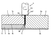
- Two sheets to be joined 1,2 different thickness lie with their upper outer sides 1a, 2a in a plane, while their lower outer sides 1b, 2b are offset in height against each other.
- the thinner sheet 1 is supported on the underside of a base 3, whose thickness is equal to the difference of the thicknesses of the two sheets 1,2. Due to this dimensioning lies the bottom 3a of the base 3 in a plane with the lower outside 2b of the thicker sheet.
- the sheets 1,2 with the supporting base 3 are positioned on a common base 6.
- a rotating tool 4 is attached from above, which consists of a rotor 4a with an end-face friction surface 4a * and an end face-mounted axial friction pin 4b.
- the rotor 4 rests with its front-side friction surface 4 a * over the entire surface of the upper outer sides 1 a, 2 a of the sheets 1,2.
- Its friction pin 4b extends over the entire height of the butt joint. However, it can even protrude into a mold cavity 5, which is formed by the thickness jump transition of the two sheets 1, 2 and a rounded edge 3 b of the base 3.
- the base 3 rests firmly both on the lower outer side 1b of the sheet 1 and laterally on the thicker sheet 2, forms the rounded edge 3b together with the thickness jump transition for emerging from the butt joint, plasticized metal, the mold cavity 5 for a groove, the one represents at least kerbarmen thickness jump transition.
Landscapes
- Engineering & Computer Science (AREA)
- Mechanical Engineering (AREA)
- Pressure Welding/Diffusion-Bonding (AREA)
- Lining Or Joining Of Plastics Or The Like (AREA)
Description
- Die Erfindung betrifft ein Verfahren zum Fügen von zwei Werkstücken aus einem durch Erwärmen plastifizierbaren Werkstoff, insbesondere Metall, insbesondere in Form von Blechen, im Stumpfstoß, die mit ihren Außenseiten auf ihrer einen Seite in einer Ebene liegen und auf ihrer anderen Seite gegeneinander versetzt sind, durch Rührreibschweißen mit einem Werkzeug, das auf einer stirnseitigen Reibfläche eines Rotors einen axialen Reibstift trägt, der durch den Stumpfstoß geführt wird, nach den Merkmalen des Oberbegriffs des Anspruchs 1. Ein derartiges Verfahren ist aus JP10249553 bekannt.
- Verfahren zum Fügen von Blechen im Stumpfstoß sind bekannt (EP 0 615 480 B1; EP 0 752 926 B1; EP 0 810 054 B1). Bei allen diesen Verfahren, bei denen die am Stumpfstoß angrenzenden Werkstücke dieselbe Dicke haben, ist es üblich, daß das rotierende Werkzeug an den oberen, stufenlos ineinander übergehenden Außenseiten ansetzt und die Werkstücke an ihren ebenfalls stufenlos ineinander übergehenden Unterseiten auf einer Unterlage abgestützt sind. Im Zusammenhang mit diesen Fügeverfahren ist es auch bekannt, daß das Werkzeug mit seiner stirnseitigen Reibfläche des Rotors vollflächig an den Werkstücken anliegt und die die Werkstücke abstützende Unterlage im Bereich des Stumpfstoßes eine nutenförmige Profilierung trägt, in die plastifiziertes (teigiges) Metall zur Bildung einer erhabenen Schweißhaube eingedrückt werden kann (EP 0 810 054 B1, Anspruch 4). Auch ist es bekannt, durch vollflächiges Andrücken der stirnseitigen Reibfläche des Rotors dafür zu sorgen, daß das teigige Metall nicht auf der oberen Außenseite zwischen der Reibfläche und den Werkstücken austritt sondern im Stumpfstoß verbleibt beziehungsweise nach unten weggedrückt wird (EP 0 752 926 B1, Anspruch 1).
- Sofern es bei bekannten Verfahren um das Fügen von verschieden dicken Blechen im Stumpfstoß durch Rührreibschweißen geht, liegt der Dickensprung auf der Oberseite der Werkstücke und das Werkzeug wird von oben mit oder ohne Neigung zu den Werkstücken angesetzt (JP 10-249553 A). Beim Fügen erweicht die obere freie Kante des dickeren Bleches und kann von der Reibfläche des Werkzeuges auf die Höhe des dünneren Bleches beziehungsweise eines Übergangsbereichs flachgedrückt werden. Dabei bildet sich aber neben dem Werkzeug eine nicht erwünschte Wulst. Auch ist von Nachteil, daß nur kleine Dickensprünge ausgeglichen werden können. Bei größeren Dickensprüngen ergibt sich am Dickenübergang eine hinsichtlich der Weiterverarbeitung des gefügten Bauteils, zum Beispiel durch Tiefziehen, kritische Kerbwirkung, die zu Bauteilversagen führen kann.
- Der Erfindung liegt die Aufgabe zugrunde, ein Verfahren zum Fügen von zwei Werkstücken aus Metall, insbesondere Blechen, im Stumpfstoß durch Rührreibschweißen zu entwickeln, bei dem die Werkstücke auch bei großen Dickenunterschieden im Stumpfstoß über ihre volle Höhe miteinander verschweißt werden und bei dem man hinsichtlich der Kerbwirkung einen unkritischen Dickensprungübergang erhält.
- Diese Aufgabe wird erfindungsgemäß bei einem Verfahren der eingangs genannten Art dadurch gelöst, daß das Werkzeug auf der einen Seite mit den in einer Ebene liegenden Außenseiten der Werkstücke angesetzt wird, wobei die Reibfläche des Rotors vollflächig anliegt und daß auf der anderen Seite der Werkstücke das dünnere Werkstück auf einem Sockel abgestützt wird, der seitlich am dickeren Werkstück anliegt und am Übergang vom dünneren zum dickeren Werkstück eine abgerundete Kante aufweist, die aus dem Stumpfstoß herausgedrücktem, plastifiziertem Metall als Form für eine Hohlkehle dient.
- Bei dem erfindungsgemäßen Verfahren erfolgt eine Verschweißung der beiden Werkstücke über die gesamte Höhe des Stumpfstoßes. Da die Reibfläche des Rotors vollflächig anliegt, kann kein plastifiziertes Material am Rotor austreten, vielmehr wird es in Richtung des Dickensprungs verdrängt und füllt den hier freigelassenen Formhohlraum zur Bildung einer Hohlkehle aus. Im Ergebnis erhält man also ein aus zwei Werkstücken unterschiedlicher Dicke im Stumpfstoß über die gesamte Höhe des Stumpfstoßes verschweißtes Bauteil mit zumindest kerbarmen Dickensprungübergang.
- Nach einer Ausgestaltung der Erfindung ist die Dicke des Sockels gleich dem Versatz (Dickensprung) der Werkstücke, wobei der Sockel und das dickere Werkstück an ihren so stufenlos ineinander übergehenden Außenseiten auf einer gemeinsamen Unterlage aufliegen. Der Sockel kann in die Unterlage integriert sein. Die Unterlage kann eben oder als Rolle ausgebildet sein, wobei sie vorzugsweise aus zwei axial nebeneinander angeordneten, zylindrischen Körpern besteht.
- Nach einer weiteren Ausgestaltung der Erfindung erstreckt sich der Reibstift über eine Länge, die ein Aufschmelzen der Werkstücke über die gesamte Höhe des Stumpfstoßes gewährleistet. Dies ist insbesondere dann gewährleistet, wenn der Reibstift eine Länge hat, die zwischen den Dicken der Werkstücke liegt.
- Besonders vorteilhaft ist es für die Ausbildung der Hohlkehle, wenn der Reibstift ein schraubenförmiges Profil hat. Dieses schraubenförmige Profil sorgt nämlich in Verbindung mit der entsprechend angepaßten Rotation dafür, daß das plastifizierte Metall in Richtung der Hohlkehle gefördert wird.
- Im folgenden wird die Erfindung anhand einer Zeichnung näher erläutert, die in schematischer Darstellung zwei zu fügende Bleche während des Fügens durch Rührreibschweißen in schematischer Darstellung im Querschnitt quer zum Stumpfstoß zeigt.
- Zwei zu fügende Bleche 1,2 unterschiedlicher Dicke liegen mit ihren oberen Außenseiten 1a,2a in einer Ebene, während ihre unteren Außenseiten 1b,2b in der Höhe gegeneinander versetzt sind. Das dünnere Blech 1 ist unterseitig an einem Sockel 3 abgestützt, dessen Dicke gleich der Differenz der Dicken der beiden Bleche 1,2 ist. Aufgrund dieser Dimensionierung liegt die Unterseite 3a des Sockels 3 in einer Ebene mit der unteren Außenseite 2b des dickeren Bleches. Die Bleche 1,2 mit dem abstützenden Sockel 3 sind auf einer gemeinsamen Unterlage 6 positioniert.
- Für das Rührreibschweißen wird von oben ein rotierendes Werkzeug 4 angesetzt, das aus einem Rotor 4a mit einer stirnseitigen Reibfläche 4a* und einem stirnseitig angesetzten axialen Reibstift 4b besteht. Der Rotor 4 liegt mit seiner stirnseitigen Reibfläche 4a* vollflächig an den oberen Außenseiten 1a,2a der Bleche 1,2 an. Sein Reibstift 4b erstreckt sich über die gesamte Höhe des Stumpfstoßes. Er kann allerdings sogar bis in einen Formhohlraum 5 ragen, der vom Dickensprungübergang der beiden Bleche 1,2 und einer abgerundeten Kante 3b des Sockels 3 gebildet wird. Da der Sockel 3 sowohl an der unteren Außenseite 1b des Bleches 1 als auch seitlich am dickeren Blech 2 fest anliegt, bildet die abgerundete Kante 3b zusammen mit dem Dickensprungübergang für das aus dem Stumpfstoß austretende, plastifizierte Metall den Formhohlraum 5 für eine Hohlkehle, die einen mindestens kerbarmen Dickensprungübergang darstellt.
Claims (8)
- Verfahren zum Fügen von zwei Werkstücken (1,2) aus einem durch Erwärmen plastifizierbaren Werkstoff, insbesondere Metall, insbesondere in Form von Blechen, im Stumpfstoß, die mit ihren Außenseiten (1a, 1b, 2a, 2b) auf ihrer einen Seite in einer Ebene liegen und auf ihrer anderen Seite gegeneinander versetzt sind, durch Rührreibschweißen mit einem Werkzeug (4), das auf einer stirnseitigen Reibfläche (4a*) eines Rotors (4a) einen axialen Reibstift (4b) trägt, der durch den Stumpfstoß geführt wird,
dadurch gekennzeichnet, daß das Werkzeug (4) auf der einen Seite mit den in einer Ebene liegenden Außenseiten (1a,2a) der Werkstücke (1,2) angesetzt wird, wobei die Reibfläche (4a*) vollflächig anliegt, und daß auf der anderen Seite der Werkstücke (1,2) das dünnere Werkstück (1) auf einem Sockel (3) abgestützt wird, der seitlich am dickeren Werkstück (2) anliegt und am Übergang vom dünneren zum dickeren Werkstück (1,2) eine abgerundete Kante (3b) aufweist, die aus dem Stumpfstoß gefördertem, plastifiziertem Metall als Form für eine Hohlkehle dient. - Verfahren nach Anspruch 1,
dadurch gekennzeichnet, daß die Dicke des Sockels (3) gleich dem Versatz (Dickensprung) der Werkstücke (1,2) ist und der Sockel (3) und das dickere Werkstück (2) an ihren so stufenlos ineinander übergehenden Außenseiten (3a,2b) auf einer gemeinsamen Unterlage (6) aufliegen. - Verfahren nach Anspruch 2,
dadurch gekennzeichnet, daß die Unterlage (6) eben ist. - Verfahren nach Anspruch 2,
dadurch gekennzeichnet, daß der Sockel (3) in die Unterlage (6) integriert ist. - Verfahren nach Anspruch 4,
dadurch gekennzeichnet, daß die Unterlage als Rolle ausgebildet ist. - Verfahren nach Anspruch 5,
dadurch gekennzeichnet, daß die Rolle aus zwei axial nebeneinander angeordneten Teilen besteht. - Verfahren nach einem der Ansprüche 1 bis 6,
dadurch gekennzeichnet, daß der Reibstift (3b) eine Länge hat, die zwischen den Dicken der Werkstücke (1,2) liegt. - Verfahren nach einem der Ansprüche 1 bis 7,
dadurch gekennzeichnet, daß der Reibstift (3b) ein schraubenförmiges Profil hat.
Applications Claiming Priority (2)
| Application Number | Priority Date | Filing Date | Title |
|---|---|---|---|
| DE10063920A DE10063920C2 (de) | 2000-12-20 | 2000-12-20 | Verfahren zum Fügen von zwei Werkstücken aus einem durch Erwärmen plastifizierbaren Werkstoff, insbesondere Metall, insbesondere in Form von Blechen, im Stumpfstoß |
| DE10063920 | 2000-12-20 |
Publications (3)
| Publication Number | Publication Date |
|---|---|
| EP1216782A2 EP1216782A2 (de) | 2002-06-26 |
| EP1216782A3 EP1216782A3 (de) | 2003-11-05 |
| EP1216782B1 true EP1216782B1 (de) | 2007-04-04 |
Family
ID=7668235
Family Applications (1)
| Application Number | Title | Priority Date | Filing Date |
|---|---|---|---|
| EP01126644A Expired - Lifetime EP1216782B1 (de) | 2000-12-20 | 2001-11-08 | Verfahren zum Fügen von zwei Werkstücken aus einem durch Erwärmen plastifizierbaren Werkstoff, insbesondere Metall, insbesondere in Form von Blechen, im Stumpfstoss |
Country Status (4)
| Country | Link |
|---|---|
| EP (1) | EP1216782B1 (de) |
| AT (1) | ATE358546T1 (de) |
| DE (2) | DE10063920C2 (de) |
| ES (1) | ES2284578T3 (de) |
Families Citing this family (3)
| Publication number | Priority date | Publication date | Assignee | Title |
|---|---|---|---|---|
| US20050045603A1 (en) * | 2003-08-27 | 2005-03-03 | Kiehl Mark W. | Method of forming multi-metallic articles from multi-metallic sheets |
| EP2810735B1 (de) | 2013-06-05 | 2016-08-10 | Airbus Defence and Space GmbH | Reibrührwerkzeug mit nicht- umfänglicher Schulter und damit durchführbares Reibrührverfahren |
| CN106001906B (zh) * | 2016-07-08 | 2019-01-01 | 陕西飞机工业(集团)有限公司 | 一种台阶结构焊缝搅拌摩擦焊接方法 |
Family Cites Families (4)
| Publication number | Priority date | Publication date | Assignee | Title |
|---|---|---|---|---|
| GB9125978D0 (en) * | 1991-12-06 | 1992-02-05 | Welding Inst | Hot shear butt welding |
| NO942790D0 (no) * | 1994-03-28 | 1994-07-27 | Norsk Hydro As | Fremgangsmåte ved friksjonssveising og anordning for samme |
| US5769306A (en) * | 1996-05-31 | 1998-06-23 | The Boeing Company | Weld root closure method for friction stir welds |
| JP3290608B2 (ja) * | 1997-03-07 | 2002-06-10 | 昭和電工株式会社 | 摩擦攪拌接合方法 |
-
2000
- 2000-12-20 DE DE10063920A patent/DE10063920C2/de not_active Expired - Fee Related
-
2001
- 2001-11-08 ES ES01126644T patent/ES2284578T3/es not_active Expired - Lifetime
- 2001-11-08 EP EP01126644A patent/EP1216782B1/de not_active Expired - Lifetime
- 2001-11-08 AT AT01126644T patent/ATE358546T1/de not_active IP Right Cessation
- 2001-11-08 DE DE50112286T patent/DE50112286D1/de not_active Expired - Lifetime
Also Published As
| Publication number | Publication date |
|---|---|
| ES2284578T3 (es) | 2007-11-16 |
| ATE358546T1 (de) | 2007-04-15 |
| EP1216782A3 (de) | 2003-11-05 |
| DE10063920C2 (de) | 2003-01-16 |
| DE10063920A1 (de) | 2002-09-12 |
| EP1216782A2 (de) | 2002-06-26 |
| DE50112286D1 (de) | 2007-05-16 |
Similar Documents
| Publication | Publication Date | Title |
|---|---|---|
| DE69736017T2 (de) | Plattenstruktur und Reibschweissverfahren | |
| DE69919742T2 (de) | Verfahren zur herstellung eines bauteiles | |
| DE69834454T2 (de) | Bauelement und Reibrührschweißverfahren | |
| DE60006450T2 (de) | Herstellungsverfahren eines strukturellen Körpers mit drehendem Reibungschweissen | |
| DE60027687T2 (de) | Drehendes Reibungschweissverfahren und struktureller Körper. | |
| DE60221934T2 (de) | Reibrührschweissverfahren und hohles Formelement für das Reibrührschweissen | |
| DE69502716T2 (de) | Oszillierendes reibungsschweissen | |
| DE3241183A1 (de) | Saegekette und verfahren zu ihrer herstellung | |
| DE4118664A1 (de) | Fuehrungsschiene in lamellierter bauweise | |
| DE60102997T2 (de) | Reibrührschweißverfahren | |
| EP3676079A1 (de) | KONTAKTSCHWEIßHEIZKOMPONENTE UND SCHWEIßAUTOMAT | |
| DE2552622B2 (de) | Plattenfoermiges hohlbauteil | |
| EP1931494B1 (de) | Verbindungselement | |
| EP2020285A2 (de) | Bauteilanordnung | |
| DE10063920C2 (de) | Verfahren zum Fügen von zwei Werkstücken aus einem durch Erwärmen plastifizierbaren Werkstoff, insbesondere Metall, insbesondere in Form von Blechen, im Stumpfstoß | |
| DE19645517A1 (de) | Türblatt, insbesondere für Aufzugstüren | |
| EP1797987B1 (de) | Bimetallisches Verbindungselement | |
| EP1083031B1 (de) | Sägekette für ein Werkzeug zum Trennen von Sandwichplatten | |
| DE2016708C3 (de) | Karosserieprofil, insbesondere für die Karosserie von Kraftfahrzeugen | |
| EP0042146B1 (de) | Löt-oder Schweissverbindung von Profilen und Verfahren zu ihrer Herstellung | |
| EP0580824A1 (de) | Wischarm, insbesondere zur reinigung von scheiben an kraftfahrzeugen | |
| DE2847023C2 (de) | Spiegelpreßschweißvorrichtung zum Verbinden von Kunststoffprofilen | |
| EP2030825A1 (de) | Verfahren zum Herstellen einer Klemmleiste | |
| DE10001523C1 (de) | Verfahren zur Herstellung von Bauelementen in Compound-Bauweise | |
| DE4443842A1 (de) | Verbindung für Blechränder sowie Verfahren und Vorrichtung hierzu |
Legal Events
| Date | Code | Title | Description |
|---|---|---|---|
| PUAI | Public reference made under article 153(3) epc to a published international application that has entered the european phase |
Free format text: ORIGINAL CODE: 0009012 |
|
| AK | Designated contracting states |
Kind code of ref document: A2 Designated state(s): AT BE CH CY DE DK ES FI FR GB GR IE IT LI LU MC NL PT SE TR |
|
| AX | Request for extension of the european patent |
Free format text: AL;LT;LV;MK;RO;SI |
|
| PUAL | Search report despatched |
Free format text: ORIGINAL CODE: 0009013 |
|
| AK | Designated contracting states |
Kind code of ref document: A3 Designated state(s): AT BE CH CY DE DK ES FI FR GB GR IE IT LI LU MC NL PT SE TR |
|
| AX | Request for extension of the european patent |
Extension state: AL LT LV MK RO SI |
|
| 17P | Request for examination filed |
Effective date: 20031129 |
|
| AKX | Designation fees paid |
Designated state(s): AT BE CH CY DE DK ES FI FR GB GR IE IT LI LU MC NL PT SE TR |
|
| RAP1 | Party data changed (applicant data changed or rights of an application transferred) |
Owner name: THYSSENKRUPP STEEL AG |
|
| GRAP | Despatch of communication of intention to grant a patent |
Free format text: ORIGINAL CODE: EPIDOSNIGR1 |
|
| GRAS | Grant fee paid |
Free format text: ORIGINAL CODE: EPIDOSNIGR3 |
|
| GRAA | (expected) grant |
Free format text: ORIGINAL CODE: 0009210 |
|
| AK | Designated contracting states |
Kind code of ref document: B1 Designated state(s): AT BE CH CY DE DK ES FI FR GB GR IE IT LI LU MC NL PT SE TR |
|
| PG25 | Lapsed in a contracting state [announced via postgrant information from national office to epo] |
Ref country code: FI Free format text: LAPSE BECAUSE OF FAILURE TO SUBMIT A TRANSLATION OF THE DESCRIPTION OR TO PAY THE FEE WITHIN THE PRESCRIBED TIME-LIMIT Effective date: 20070404 |
|
| REG | Reference to a national code |
Ref country code: GB Ref legal event code: FG4D Free format text: NOT ENGLISH |
|
| REG | Reference to a national code |
Ref country code: CH Ref legal event code: EP |
|
| REF | Corresponds to: |
Ref document number: 50112286 Country of ref document: DE Date of ref document: 20070516 Kind code of ref document: P |
|
| REG | Reference to a national code |
Ref country code: IE Ref legal event code: FG4D Free format text: LANGUAGE OF EP DOCUMENT: GERMAN |
|
| PG25 | Lapsed in a contracting state [announced via postgrant information from national office to epo] |
Ref country code: SE Free format text: LAPSE BECAUSE OF FAILURE TO SUBMIT A TRANSLATION OF THE DESCRIPTION OR TO PAY THE FEE WITHIN THE PRESCRIBED TIME-LIMIT Effective date: 20070704 |
|
| GBT | Gb: translation of ep patent filed (gb section 77(6)(a)/1977) |
Effective date: 20070705 |
|
| PG25 | Lapsed in a contracting state [announced via postgrant information from national office to epo] |
Ref country code: PT Free format text: LAPSE BECAUSE OF FAILURE TO SUBMIT A TRANSLATION OF THE DESCRIPTION OR TO PAY THE FEE WITHIN THE PRESCRIBED TIME-LIMIT Effective date: 20070904 |
|
| ET | Fr: translation filed | ||
| REG | Reference to a national code |
Ref country code: ES Ref legal event code: FG2A Ref document number: 2284578 Country of ref document: ES Kind code of ref document: T3 |
|
| REG | Reference to a national code |
Ref country code: IE Ref legal event code: FD4D |
|
| PG25 | Lapsed in a contracting state [announced via postgrant information from national office to epo] |
Ref country code: IE Free format text: LAPSE BECAUSE OF FAILURE TO SUBMIT A TRANSLATION OF THE DESCRIPTION OR TO PAY THE FEE WITHIN THE PRESCRIBED TIME-LIMIT Effective date: 20070404 Ref country code: DK Free format text: LAPSE BECAUSE OF FAILURE TO SUBMIT A TRANSLATION OF THE DESCRIPTION OR TO PAY THE FEE WITHIN THE PRESCRIBED TIME-LIMIT Effective date: 20070404 |
|
| PLBE | No opposition filed within time limit |
Free format text: ORIGINAL CODE: 0009261 |
|
| STAA | Information on the status of an ep patent application or granted ep patent |
Free format text: STATUS: NO OPPOSITION FILED WITHIN TIME LIMIT |
|
| 26N | No opposition filed |
Effective date: 20080107 |
|
| PG25 | Lapsed in a contracting state [announced via postgrant information from national office to epo] |
Ref country code: GR Free format text: LAPSE BECAUSE OF FAILURE TO SUBMIT A TRANSLATION OF THE DESCRIPTION OR TO PAY THE FEE WITHIN THE PRESCRIBED TIME-LIMIT Effective date: 20070705 |
|
| PG25 | Lapsed in a contracting state [announced via postgrant information from national office to epo] |
Ref country code: MC Free format text: LAPSE BECAUSE OF NON-PAYMENT OF DUE FEES Effective date: 20071130 |
|
| PG25 | Lapsed in a contracting state [announced via postgrant information from national office to epo] |
Ref country code: CH Free format text: LAPSE BECAUSE OF NON-PAYMENT OF DUE FEES Effective date: 20071130 Ref country code: LI Free format text: LAPSE BECAUSE OF NON-PAYMENT OF DUE FEES Effective date: 20071130 |
|
| REG | Reference to a national code |
Ref country code: CH Ref legal event code: PL |
|
| PG25 | Lapsed in a contracting state [announced via postgrant information from national office to epo] |
Ref country code: AT Free format text: LAPSE BECAUSE OF NON-PAYMENT OF DUE FEES Effective date: 20071108 |
|
| PG25 | Lapsed in a contracting state [announced via postgrant information from national office to epo] |
Ref country code: CY Free format text: LAPSE BECAUSE OF FAILURE TO SUBMIT A TRANSLATION OF THE DESCRIPTION OR TO PAY THE FEE WITHIN THE PRESCRIBED TIME-LIMIT Effective date: 20070404 |
|
| PG25 | Lapsed in a contracting state [announced via postgrant information from national office to epo] |
Ref country code: LU Free format text: LAPSE BECAUSE OF NON-PAYMENT OF DUE FEES Effective date: 20071108 |
|
| PG25 | Lapsed in a contracting state [announced via postgrant information from national office to epo] |
Ref country code: TR Free format text: LAPSE BECAUSE OF FAILURE TO SUBMIT A TRANSLATION OF THE DESCRIPTION OR TO PAY THE FEE WITHIN THE PRESCRIBED TIME-LIMIT Effective date: 20070404 |
|
| REG | Reference to a national code |
Ref country code: DE Ref legal event code: R082 Ref document number: 50112286 Country of ref document: DE Representative=s name: COHAUSZ & FLORACK PATENT- UND RECHTSANWAELTE P, DE |
|
| REG | Reference to a national code |
Ref country code: DE Ref legal event code: R082 Ref document number: 50112286 Country of ref document: DE Representative=s name: COHAUSZ & FLORACK PATENT- UND RECHTSANWAELTE P, DE Effective date: 20140408 Ref country code: DE Ref legal event code: R081 Ref document number: 50112286 Country of ref document: DE Owner name: WISCO TAILORED BLANKS GMBH, DE Free format text: FORMER OWNER: THYSSENKRUPP STEEL EUROPE AG, 47166 DUISBURG, DE Effective date: 20140408 |
|
| REG | Reference to a national code |
Ref country code: GB Ref legal event code: 732E Free format text: REGISTERED BETWEEN 20140717 AND 20140723 |
|
| REG | Reference to a national code |
Ref country code: NL Ref legal event code: SD Effective date: 20141022 Ref country code: NL Ref legal event code: TD Effective date: 20141022 |
|
| REG | Reference to a national code |
Ref country code: FR Ref legal event code: CD Owner name: WISCO TAILORED BLANKS GMBH, DE Effective date: 20141229 Ref country code: FR Ref legal event code: TP Owner name: WISCO TAILORED BLANKS GMBH, DE Effective date: 20141229 |
|
| REG | Reference to a national code |
Ref country code: ES Ref legal event code: PC2A Owner name: WISCO TAILORED BLANKS GMBH Effective date: 20150324 |
|
| REG | Reference to a national code |
Ref country code: FR Ref legal event code: PLFP Year of fee payment: 15 |
|
| REG | Reference to a national code |
Ref country code: FR Ref legal event code: PLFP Year of fee payment: 16 |
|
| PG25 | Lapsed in a contracting state [announced via postgrant information from national office to epo] |
Ref country code: BE Free format text: LAPSE BECAUSE OF NON-PAYMENT OF DUE FEES Effective date: 20161130 |
|
| PG25 | Lapsed in a contracting state [announced via postgrant information from national office to epo] |
Ref country code: BE Free format text: LAPSE BECAUSE OF NON-PAYMENT OF DUE FEES Effective date: 20161130 |
|
| PGRI | Patent reinstated in contracting state [announced from national office to epo] |
Ref country code: BE Effective date: 20170112 |
|
| REG | Reference to a national code |
Ref country code: FR Ref legal event code: PLFP Year of fee payment: 17 |
|
| PGFP | Annual fee paid to national office [announced via postgrant information from national office to epo] |
Ref country code: NL Payment date: 20181120 Year of fee payment: 18 |
|
| PGFP | Annual fee paid to national office [announced via postgrant information from national office to epo] |
Ref country code: DE Payment date: 20181120 Year of fee payment: 18 |
|
| PGFP | Annual fee paid to national office [announced via postgrant information from national office to epo] |
Ref country code: IT Payment date: 20181126 Year of fee payment: 18 Ref country code: BE Payment date: 20181122 Year of fee payment: 18 Ref country code: ES Payment date: 20181219 Year of fee payment: 18 Ref country code: FR Payment date: 20181121 Year of fee payment: 18 Ref country code: GB Payment date: 20181120 Year of fee payment: 18 |
|
| REG | Reference to a national code |
Ref country code: DE Ref legal event code: R119 Ref document number: 50112286 Country of ref document: DE |
|
| REG | Reference to a national code |
Ref country code: NL Ref legal event code: MM Effective date: 20191201 |
|
| REG | Reference to a national code |
Ref country code: BE Ref legal event code: MM Effective date: 20191130 |
|
| GBPC | Gb: european patent ceased through non-payment of renewal fee |
Effective date: 20191108 |
|
| PG25 | Lapsed in a contracting state [announced via postgrant information from national office to epo] |
Ref country code: NL Free format text: LAPSE BECAUSE OF NON-PAYMENT OF DUE FEES Effective date: 20191201 |
|
| PG25 | Lapsed in a contracting state [announced via postgrant information from national office to epo] |
Ref country code: FR Free format text: LAPSE BECAUSE OF NON-PAYMENT OF DUE FEES Effective date: 20191130 Ref country code: GB Free format text: LAPSE BECAUSE OF NON-PAYMENT OF DUE FEES Effective date: 20191108 Ref country code: DE Free format text: LAPSE BECAUSE OF NON-PAYMENT OF DUE FEES Effective date: 20200603 Ref country code: IT Free format text: LAPSE BECAUSE OF NON-PAYMENT OF DUE FEES Effective date: 20191108 |
|
| PG25 | Lapsed in a contracting state [announced via postgrant information from national office to epo] |
Ref country code: BE Free format text: LAPSE BECAUSE OF NON-PAYMENT OF DUE FEES Effective date: 20191130 |
|
| REG | Reference to a national code |
Ref country code: ES Ref legal event code: FD2A Effective date: 20210526 |
|
| PG25 | Lapsed in a contracting state [announced via postgrant information from national office to epo] |
Ref country code: ES Free format text: LAPSE BECAUSE OF NON-PAYMENT OF DUE FEES Effective date: 20191109 |