EP1216441B1 - Graphical programming system with distributed block diagram execution and user interface display - Google Patents
Graphical programming system with distributed block diagram execution and user interface display Download PDFInfo
- Publication number
- EP1216441B1 EP1216441B1 EP00957450.0A EP00957450A EP1216441B1 EP 1216441 B1 EP1216441 B1 EP 1216441B1 EP 00957450 A EP00957450 A EP 00957450A EP 1216441 B1 EP1216441 B1 EP 1216441B1
- Authority
- EP
- European Patent Office
- Prior art keywords
- computer
- graphical program
- user interface
- operable
- program
- Prior art date
- Legal status (The legal status is an assumption and is not a legal conclusion. Google has not performed a legal analysis and makes no representation as to the accuracy of the status listed.)
- Expired - Lifetime
Links
Images


Classifications
-
- G—PHYSICS
- G06—COMPUTING; CALCULATING OR COUNTING
- G06F—ELECTRIC DIGITAL DATA PROCESSING
- G06F8/00—Arrangements for software engineering
- G06F8/30—Creation or generation of source code
- G06F8/34—Graphical or visual programming
-
- G—PHYSICS
- G06—COMPUTING; CALCULATING OR COUNTING
- G06F—ELECTRIC DIGITAL DATA PROCESSING
- G06F9/00—Arrangements for program control, e.g. control units
- G06F9/06—Arrangements for program control, e.g. control units using stored programs, i.e. using an internal store of processing equipment to receive or retain programs
- G06F9/44—Arrangements for executing specific programs
- G06F9/445—Program loading or initiating
- G06F9/44505—Configuring for program initiating, e.g. using registry, configuration files
-
- G—PHYSICS
- G06—COMPUTING; CALCULATING OR COUNTING
- G06F—ELECTRIC DIGITAL DATA PROCESSING
- G06F9/00—Arrangements for program control, e.g. control units
- G06F9/06—Arrangements for program control, e.g. control units using stored programs, i.e. using an internal store of processing equipment to receive or retain programs
- G06F9/44—Arrangements for executing specific programs
- G06F9/451—Execution arrangements for user interfaces
- G06F9/454—Multi-language systems; Localisation; Internationalisation
Definitions
- the present invention relates to the field of graphical programming and virtual instrumentation.
- the invention relates to a system and method wherein a graphical program block diagram executes on a server computer, and one or more client computers receive and display a graphical program user interface panel corresponding to the block diagram, wherein the graphical program user interface panel can be used to provide input to or display output to from the block diagram.
- the present invention further relates to a distributed virtual instrumentation system, wherein a block diagram executes on a server computer and one or more front panels are displayed on client computers.
- high level text-based programming languages have been used by programmers in writing application programs.
- Many different high level text-based programming languages exist including BASIC, C, FORTRAN, Pascal, COBOL, ADA, APL, etc.
- Programs written in these high level languages are translated to the machine language level by translators known as compilers or interpreters.
- the high level text-based programming languages in this level, as well as the assembly language level, are referred to as text-based programming environments.
- Examples of fields in which computer systems are employed to model and/or control physical systems are the fields of instrumentation, process control, industrial automation, and simulation.
- Computer modeling or control of devices such as instruments or industrial automation hardware has become increasingly desirable in view of the increasing complexity and variety of instruments and devices available for use.
- computer programs used to control such systems had to be written in conventional text-based programming languages such as, for example, assembly language, C, FORTRAN, BASIC, or Pascal.
- U.S. Patent Nos. 4,901,221 ; 4,914,568 ; 5,291,587 ; 5,301,301 ; and 5,301,336 ; among others, to Kodosky et al disclose a graphical system and method for modeling a process, i.e., a graphical programming environment, which enables a user to easily and intuitively model a process.
- the graphical programming environment disclosed in Kodosky et al can be considered the highest and most intuitive way in which to interact with a computer.
- a graphically based programming environment can be represented at a level above text-based high level programming languages such as C, Pascal, etc.
- the method disclosed in Kodosky et al allows a user to construct a diagram using a block diagram editor, such that the diagram created graphically displays a procedure or method for accomplishing a certain result, such as manipulating one or more input variables to produce one or more output variables.
- data structures may be automatically constructed which characterize an execution procedure which corresponds to the displayed procedure.
- the graphical program may be compiled or interpreted by a computer using these data structures. Therefore, a user can create a computer program solely by using a graphically based programming environment. This graphically based programming environment may be used for creating virtual instrumentation systems, industrial automation systems, modeling processes, and simulation, as well as for any type of general programming.
- Kodosky et al teaches a graphical programming environment wherein a user places or manipulates icons in a block diagram using a block diagram editor to create a graphical "program."
- a graphical program for controlling or modeling devices such as instruments, processes or industrial automation hardware, is referred to as a virtual instrument (VI).
- VI virtual instrument
- a user may create a front panel or user Interface panel.
- the front panel includes various front panel objects, such as controls or indicators, that represent or display the respective input and output that will be used by the graphical program or VI, and may include other icons which represent devices being controlled.
- corresponding icons or terminals may be automatically created in the block diagram by the block diagram editor.
- the user can place terminal icons or input/output blocks in the block diagram which may cause the display of corresponding front panel objects in the front panel, either at edit time or at nm time.
- the user selects various functions that accomplish his desired result and connects the function icons together.
- the functions may be connected in a data flow and/or control flow format.
- the functions may be connected between the terminals of the respective controls and indicators.
- the user may create or assemble a data flow program, referred to as a block diagram, representing the graphical data flow which accomplishes his desired function.
- the assembled graphical program may then be compiled or interpreted to produce machine language that accomplishes the desired method or process as shown in the block diagram.
- a user may input data to a virtual Instrument using front panel controls. This input data propagates through the data flow block diagram or graphical program and appears as changes an the output indicators.
- the front panel can he analogized to the front panel of an instrument.
- the front panel can be analogized to the MMI (Man Machine Interface) of a device.
- the user may adjust the controls on the front panel to affect the input and view the output on the respective indicators.
- the front panel may be used merely to view the input and output, and the input may not be interactively manipulable by the user during program execution.
- graphical programming has become a powerful tool available to programmers. Graphical programming environments such as the National Instruments LabVIEW product have become very popular.
- Tools such as LabVIEW have greatly increased the productivity of programmers, and increasing numbers of programmers are using graphical programming environments to develop their software applications.
- graphical programming tools are being used for test and measurement, data acquisition, process control, man machine interface (MMI), supervisory control and data acquisition (SCADA) applications, simulation, and machine vision applications, among others.
- MMI man machine interface
- SCADA supervisory control and data acquisition
- a user developing an instrumentation application such as a test and measurement application or a process control application, may desire the graphical program to execute on a computer located in a laboratory or manufacturing facility, but may want to interact with the program by viewing the program's user interface panel from another computer, such as a workstation located in the user's office.
- a program developer may construct a graphical program and desire to enable others to interact with or view the results of the program.
- the program developer may desire to enable multiple Internet users to connect to the computer running the graphical program and view the graphical program's user interface.
- EP 0 398 646 A2 describes user interfaces in general. However, also EP 0 398 646 A2 does not allow to separate the user interface panel to another computer, much less to transfer the description of the user interface panel independently from the data to be displayed in the user interface panel.
- One aspect of the present invention comprises a system and method enabling distributed display of the user interface of a graphical program executing on a server computer.
- the system may includes a server computer where a graphical program executes, and one or more client computers connected to the server computer which receive and display a user interface, e.g., one or more user interface panels, corresponding to the graphical program.
- the user interface can be used from the client computer(s) to provide input to or display output from the graphical program during program execution.
- the invention may comprise a distributed virtual instrumentation system, wherein a graphical program executes on a server computer to perform a measurement or automation function, and one or more front panels are displayed on client computers, thus enabling one or more users to remotely view and/or control the measurement or automation function.
- a user of a client computer specifies a remote server computer on which a graphical program executes.
- the remote server information may be specified in various ways.
- the information may be specified as a uniform resource locator (URL), as an internet protocol (IP) address, as a machine name and TCP/IP port number, etc.
- a user may specify the remote computer by entering a URL into an application such as a web browser or other application with web-browsing functionality.
- the application may include a protocol handler plug-in enabled to process the URL and connect to the remote computer.
- the user may also specify the particular graphical program desired.
- a parameter indicating the name of the graphical program may be appended to the URL, etc.
- the user may also specify the remote computer without also specifying the particular graphical program.
- the remote computer may comprise a web server.
- the user may enter the URL of a web page associated with the web server, and the web server may return a list of graphical programs running on the remote computer. The user may then select one or more graphical programs from this list.
- the user's client software is operable to then display the user interface panels associated with the selected graphical program(s) on the user's display screen.
- the user's client software comprises a web browser (or application with web-browsing functionality) with a plug-in operable to communicate with the remote graphical program.
- the plug-in may display the user interface panel directly in the web browser's window.
- the user's client software preferably communicates with an agent or software program running on the remote computer using a communication protocol based on the standard TCP/IP protocol.
- the agent on the remote computer transfers a description of the graphical program's user interface panel to the user's client software. This description may be sent in the same format used to store the user interface panel information on the remote computer.
- the user interface panel description may, of course, be sent in various other formats, e.g., as an XML description.
- the user's client-side software e.g., web browser plug-in, is preferably enabled to interpret any type of user interface panel description that it may receive from the remote computer, and is enabled to appropriately display the user interface panel to the user.
- the user interface panel may be dynamically updated during execution of the graphical program block diagram.
- the user interface panel may include a graph which displays various types of measurement data produced by the block diagram, such as an electrical signal, meteorological data, etc., and this graph may scroll on the user's display as the measured data values change in response to graphical program execution.
- the user interface panel may comprise numerical text indicators that are updated with new values periodically, etc. The user may also interact with the user interface panel on the client computer to provide input to the block diagram executing on the server computer, e.g. by issuing standard point-and-click type GUI commands.
- the user's input is passed to the remote graphical program on the server computer, and the graphical program responds accordingly.
- the user may interact with the remote graphical program exactly as he would interact with the program if it were running locally on the user's computer.
- a means for coordinating control among users may be included so that multiple users interacting with the same graphical program do not interfere with each others' actions.
- a user may also request and receive the remote graphical program's block diagram, e.g., to edit or debug the graphical program.
- a TCP/IP-based communication protocol is used for communication between the user's client software and the remote server computer executing the graphical program.
- the DataSocket system and method disclosed in U.S. Patent Application No. 09/185,161 , may be used to facilitate the communication between the user's client software and the remote computer running the graphical program.
- the DataSocket system comprises a client software component that addresses data sources/targets using a URL, much the way that a URL is used to address web pages anywhere in the world.
- the remote graphical program executes within a graphical programming environment including functionality referred to as "VI Server”.
- VI Server functionality may be used to enable user clients to connect to and interact with a remote graphical program.
- VI Server For more information on VI Server, please refer to the patent applications incorporated by reference below.
- Figure 1 Computer System Connected to a Network
- Figure 1 illustrates an exemplary computer network in which a computer system 82 is connected through a network 84 to a second computer system 86.
- the computer system 82 and the second computer system 86 can be any of various types, as desired.
- the network 84 can also be any of various types, including a LAN (local area network), WAN (wide area network), or the Internet, among others.
- a user of computer system 82 may connect to computer system 86, according to the system and method described herein.
- Computer system 82 which may be referred to as client computer system 82, comprises client software enabled to receive a description of a graphical program user interface panel and display the panel on the display screen of computer system 82.
- the client software may comprise a web browser with a web browser plug-in.
- the web browser may be the Microsoft Internet Explorer web browser, and the plug-in may be constructed according to Microsoft's Asynchronous Pluggable Protocols specification.
- Computer system 86 which may be referred to as server computer system 86, comprises a graphical program, as well as server-side programs or agents enabling the user of computer system 82 to communicate with computer system 86 according to the present invention.
- computer system 86 may include VI Server functionality, as discussed above.
- Computer system 86 preferably includes a mechanism for coordinating control of the graphical program among multiple remote users.
- Computer system 86 may distribute control of the graphical program among the users using various methods or algorithms, such as a round-robin scheme, prioritized round-robin scheme, etc.
- Various types of privileges or permissions may be assigned to different users, granting them different levels of control over the graphical program.
- the program creator may be authorized to assume complete control over the program, locking out other users.
- Other users may only be authorized to view the graphical program's user interface panel, but not to use it to control the graphical program, e.g., these users may not be allowed to provide input to the graphical program.
- Figures 2A and 2B illustrate exemplary systems that may store or use programs according to the present invention. These exemplary systems illustrate systems specialized for instrumentation, process control, or other purposes. Figures 2A and 2B illustrate exemplary server computer systems.
- the server computer 86 described above may be comprised in an instrumentation or industrial automation system, wherein the present invention allows for distributed control of a test or automation application. The present invention may of course be used in other types of applications as desired.
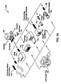
- FIG. 2A illustrates an instrumentation control system 100.
- the system 100 comprises a host computer 86 (server computer 86) which connects to one or more instruments.
- the host computer 86 comprises a CPU, a display screen, memory, and one or more input devices such as a mouse or keyboard as shown.
- the computer 86 connects through the one or more instruments to analyze, measure, or control a unit under test (UUT) or process 150.
- UUT unit under test
- the one or more instruments may include a GPIB instrument 112 and associated GPIB interface card 122, a data acquisition board 114 and associated signal conditioning circuitry 124, a VXI instrument 116, a PXT instrument 118, a video device 132 and associated image acquisition card 134, a motion control device 136 and associated motion control interface card 138, and/or one or more computer based instrument cards 142, among other types of devices.
- the GPIB instrument 112 is coupled to the computer 86 via the GPIB interface card 122 provided by the computer 86.
- the video device 132 is coupled to the computer 86 via the image acquisition card 134
- the motion control device 136 is coupled to the computer 86 through the motion control interface card 138.
- the data acquisition board 114 is coupled to the computer 86, and may interface through signal conditioning circuitry 124 to the UUT.
- the signal conditioning circuitry 124 preferably comprises an SCXI (Signal Conditioning eXtensions for Instrumentation) chassis comprising one or more SCXI modules 126.
- the GPIB card 122, the image acquisition card 134, the motion control interface card 138, and the DAQ card 114 are typically plugged in to an 110 slot in the computer 86, such as a PCI bus slot, a PC Card slot, or an ISA, EISA or MicroChannel bus slot provided by the computer 86.
- these cards 122, 134, 138 and 114 are shown external to computer 86 for illustrative purposes.
- the VXI chassis or instrument 116 is coupled to the computer 86 via a VXI bus, MXI bus, or other serial or parallel bus provided by the computer 86.
- the computer 86 preferably includes VXI interface logic, such as a VXI, MXI or GPIB interface card (not shown), which interfaces to the VXI chassis 116.
- VXI interface logic such as a VXI, MXI or GPIB interface card (not shown), which interfaces to the VXI chassis 116.
- the PXI chassis or instrument is preferably coupled to the computer 86 through the computer's PCI bus.
- a serial instrument may also be coupled to the computer 86 through a serial port, such as an RS-232 port, USB (Universal Serial bus) or IEEE 1394 or 1394.2 bus, provided by the computer 86.
- a serial port such as an RS-232 port, USB (Universal Serial bus) or IEEE 1394 or 1394.2 bus, provided by the computer 86.
- USB Universal Serial bus
- IEEE 1394 or 1394.2 bus provided by the computer 86.
- the instruments are coupled to the unit under test (UUT) or process 150, or are coupled to receive field signals, typically generated by transducers.
- the system 100 may be used in a data acquisition and control application, in a test and measurement application, a process control application, or a man-machine interface application.
- FIG. 2B illustrates an exemplary industrial automation system 160.
- the industrial automation system 160 is similar to the instrumentation or test and measurement system 100 shown in Figure 2A . Elements which are similar or identical to elements in Figure 2A have the same reference numerals for convenience.
- the system 160 comprises a computer 86 which connects to one or more devices or instruments.
- the computer 86 comprises a CPU, a display screen, memory, and one or more input devices such as a mouse or keyboard as shown.
- the computer 86 connects through the one or more devices to a process or device 150 to perform an automation function, such as MMI (Man Machine Interface), SCADA (Supervisory Control and Data Acquisition), portable or distributed data acquisition, process control, advanced analysis, or other control.
- MMI Man Machine Interface
- SCADA Supervisory Control and Data Acquisition
- the one or more devices may include a data acquisition board 114 and associated Signal conditioning circuitry 124, a PXI instrument 118, a video device 132 and associated image acquisition card 134, a motion control device 136 and associated motion control interface card 138, a fieldbus device 170 and associated fieldbus interface card 172, a PLC (Programmable Logic Controller) 176, a serial instrument 182 and associated serial interface card 184, or a distributed data acquisition system, such as the Fieldpoint system available from National Instruments, among other types of devices.
- the DAQ card 114, the PXI chassis 118, the video device 132, and the image acquisition card 136 are preferably connected to the computer 86 as described above.
- the serial instrument 182 is coupled to the computer 86 through a serial interface card 184, or through a serial port, such as an RS-232 port, provided by the computer 86.
- the PLC 176 couples to the computer 86 through a serial port, Ethernet port, or a proprietary interface.
- the fieldbus interface card 172 is preferably comprised in the computer 86 and interfaces through a fieldbus network to one or more fieldbus devices.
- Each of the DAQ card 114, the serial card 184, the fieldbus card 172, the image acquisition card 134, and the motion control card 138 are typically plugged in to an 1/0 slot in the computer 86 as described above.
- the server computer system 86 preferably includes a memory medium an which one or more computer programs or software components according to the present invention are stored.
- memory medium is intended to include an installation medium, e.g., a CD-ROM, floppy disks 104, or tape device, a computer system memory or random access memory such as DRAM, SRAM, EDO RAM, Rambus RAM, etc., or a non-volatile memory such as a magnetic media, e.g., a hard drive, or optical storage.
- the memory medium may comprise other types of memory as well, or combinations thereof.
- the memory medium may be located in a first computer in which the programs are executed, or may be located in a second different computer which connects to the first computer over a network, such as the Internet. In the latter instance, the second computer provides the program instructions to the first computer for execution.
- the server computer system 86 may take any of various forms.
- the client computer system 82 may take any of various forms, including a personal computer system, workstation, network appliance, Internet appliance, personal digital assistant (PDA), television system or other device.
- PDA personal digital assistant
- the term "computer system” can be broadly defined to encompass any device having at least one processor which executes instructions from a memory medium.
- the memory medium of the server computer 86 stores software programs for communicating with the client computer system 82, according to the present invention.
- the server computer 86 may store network communication software, e.g., TCP/IP software, and may also store application-level software, such as a graphical programming system enabled to communicate with remote computers.
- the memory medium of the client computer 82 stores software programs for communicating with the server computer system 86, according to the present invention.
- the client computer 82 may store a standard user agent, such as a web browser or other application with web-browsing functionality, and possibly a specialized browser plug-in for communicating with the server computer.
- the graphical program that users may remotely view or control is a program for data acquisition/generation, analysis, and/or display, or for controlling or modeling instrumentation or industrial automation hardware.
- the graphical program is a program constructed using the National Instruments LabVIEW graphical programming environment application, which provides specialized support for developers of instrumentation and industrial automation applications.
- Figures 2A and 2B are exemplary only, and users may remotely interact with graphical programs for any of various types of purposes in any of various applications.
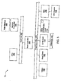
- Figure 3 is a block diagram of the computer system illustrated in Figures 1 , 2A and 2B . It is noted that any type of computer system configuration or architecture can be used as desired, and Figure 3 illustrates a representative PC embodiment. It is also noted that the computer system may be a general purpose computer system as shown in Figures 2A and 2B , a computer implemented on a VXI card installed in a VXI chassis, a computer implemented on a PXI card installed in a PXI chassis, or other types of embodiments. The elements of a computer not necessary to understand the present invention have been omitted for simplicity.
- the computer 86 (or 82) includes at least one central processing unit or CPU 160 which is coupled to a processor or host bus 162.
- the CPU 160 may be any of various types, including an x86 processor, e.g., a Pentium class, a PowerPC processor, a CPU from the SPARC family of RISC processors, as well as others.
- Main memory 166 is coupled to the host bus 162 by means of memory controller 164.
- the main memory 166 stores computer programs according to the present invention.
- the main memory 166 also stores operating system software as well as the software for Operation of the computer system, as well known to those skilled in the art.
- the computer programs of the present invention will be discussed in more detail below.
- the host bus 162 is coupled to an expansion or input/output bus 170 by means of a bus controller 168 or bus bridge logic.
- the expansion bus 170 is preferably the PCI (Peripheral Component Interconnect) expansion bus, although other bus types can be used.
- the expansion bus 170 includes slots for various devices such as the data acquisition board 114 (of Figure 2A ), a GPIB interface card 122 which provides a GPIB bus interface to the GPIB instrument 112 (of Figure 2A ), and a VXI or MXI bus card 186 coupled to the VXI chassis 116 for receiving VXI instruments.
- the computer 86 further comprises a video display subsystem 180 and hard drive 182 coupled to the expansion bus 170.
- Figures 4 - 6 Interactive Creation of a Graphical Program by a User
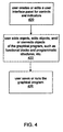
- Figure 4 is a flowchart diagram illustrating one example of how a user may interactively or manually create or edit a graphical program. As shown in the flowchart and described below, the user interactively adds various objects to a graphical program, connects them together, etc. It is noted that the various steps of Figure 4 may be performed in various orders, or omitted as desired.
- the steps are performed by a developer creating or editing a graphical program in a graphical programming environment.
- the developer may create or edit a user interface panel for displaying a graphical user interface.
- the user interface panel may comprise controls for accepting user input, displaying information such as program output, or both.
- the user interface panel may include buttons, selectable lists, text boxes, graph controls, images, etc.
- a developer may "drop" various controls or other objects onto the user interface panel, e.g., by selecting the desired control from a control palette.
- Figure 5 illustrates a simple user interface panel.
- Step 420 is not necessarily performed.
- a user interface panel may not be desired, a user interface panel may be inherently specified during creation of the block diagram, or a user interface panel may automatically be created as the user creates the executable portions of the graphical program.
- a graphical program may include a block diagram comprising objects referred to herein as "nodes" which are connected together to model the program execution logic, data flow and/or control flow.
- a block diagram node may be displayed as an icon representing the type or functionality of the node.
- Figure 6 illustrates a simple block diagram. As a developer adds objects to the user interface panel, the graphical programming environment may automatically create a corresponding object on the block diagram. Such block diagram nodes which correspond to user interface panel objects are referred to herein as user interface nodes or terminals.
- the Figure 6 block diagram node labeled "The result of 2.0 + 3.0 was:" is a user interface node corresponding to the Figure 5 user interface output indicator.
- User interface nodes may be connected with other objects or nodes in the block diagram to participate in the program logic and data/control flow.
- User interface nodes may map input/output between a user interface panel and a block diagram.
- the user interface node in Figure 6 receives data and displays the data in the corresponding user interface indicator in Figure 5 .
- step 422 of Figure 4 the developer adds other objects/nodes to or edits other objects/nodes of the graphical program.
- objects or nodes may include function nodes which perform predefined functional operations such as numeric functions, Boolean functions, string functions, array functions, error functions, file functions, application control functions, etc.
- function nodes which perform predefined functional operations such as numeric functions, Boolean functions, string functions, array functions, error functions, file functions, application control functions, etc.
- the block diagram shown in Figure 6 uses an addition function node to add two constants together.
- the developer may also add other types of nodes to the graphical program. For example, nodes may he added which represent numeric constants.
- Figure 6 illustrates numeric constant nodes representing the floating point constants 2.0 and 3.0.
- nodes which may he added include subprogram nodes for calling a graphical subprogram, global or local variable nodes for defining and using variables, etc.
- the developer may also add other types of objects to the graphical program. For example, objects representing programmatic structures such as for loops, while loops, case structures, etc. may be added.
- the developer may add nodes and other types of objects to a graphical program in various ways, e.g., by selecting a node or object from a palette that displays icons representing the various nodes and objects.
- the developer may also connect or "wire" the graphical program objects in order to achieve the desired executable logic, data flow, and/or control flow.
- the objects may include input and output terminals, and the developer may connect the output terminal of one node to the input terminal of another node, etc.
- Figure 6 illustrates one example of how objects may be connected.
- output terminals of the two numeric constant nodes are connected to the input terminals of an addition function node.
- the addition function node performs the addition operation on the numeric input.
- the output terminal of the addition function node is connected to the input of the user interface indicator node so that the result of the addition operation is displayed in the user interface panel shown in Figure 5 .
- Programmatic structure objects may also include terminals which integrate them with the other objects of the graphical program.
- a while loop may comprise a condition terminal to which an output terminal of anode supplying a Boolean value may be connected to signify when the loop should end.
- the developer saves or runs the graphical program.
- the graphical program may be saved in any of various formats. For example, a tree of data structures may be built which represents the various elements of the graphical program and the relationships among the elements, and the data structures may be saved in a binary or text format. These data structures may be compiled into machine code, or interpreted during execution. If the graphical program includes user interface panels, these panels may also be saved.
- the developer may also execute the graphical program.
- the developer may run the graphical program in any of various ways. For example, a graphical programming environment may allow a program to be run from within the development environment, or the developer may create a standalone program and run the program, etc.
- steps 420 through 426 typically occur in an iterative manner and typically occur in various orders. For example a developer may add a user interface control to a user interface panel, then connect a user interface node corresponding to the control to another node, then add and connect a function node to the program, then run the program to test it, then change the way a node is connected, etc. Also, as noted above, step 420 may be automatically (e.g., programmatically) performed in response to step 422. In addition, the user interface panel may be automatically created at edit time, or may be automatically generated at run time. Thus, the flowchart of Figure 4 is exemplary, and various steps may be combined, omitted, added, or modified as required or desired for developing different graphical programs or using different embodiments of graphical program development environments.
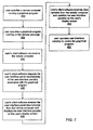
- Figure 7 is a flowchart diagram illustrating one example of a user accessing a remote graphical program, various steps of Figure 7 may be combined, altered, omitted, or may occur in different orders.
- a user specifies a remote computer.
- the user specifies a graphical program on the remote computer.
- Steps 450 and 452 may be combined into a single step.
- steps 450 and 452 may be accomplished in any of various ways.
- the remote computer and/or the remote graphical program may be implicitly specified by a user specifying a URL which references the remote computer or the remote graphical program.
- steps 450 and 452 are not necessarily performed directly by a user, but may also be performed programmatically.
- a user may operate an application that provides a reference to a remote computer and remote graphical program to client software running on the user's machine, which is described below.
- the user performs steps 450 and 452 by interacting with standard, commonly-available client software, such as a web browser or an application including web-browsing functionality, e.g., an application using the Microsoft Internet Explorer code base.
- client software such as a web browser or an application including web-browsing functionality, e.g., an application using the Microsoft Internet Explorer code base.
- the user may provide a URL to the browser application, and the browser application may then contact a web server and receive a list of graphical programs running on the web server computer or another computer. The user may then select one or more of these graphical programs, e.g. by clicking on a hypertext link, etc. Selecting a graphical program may then cause the user's browser application to invoke a browser plug-in to handle the remaining steps of Figure 7 .
- the user may still work within the context of a web browser environment, but may not interact with a web server at any point.
- the user may provide a URL to the web browser, wherein the URL comprises a protocol scheme which is not natively supported by the web browser.
- the web browser may delegate the URL to a protocol handler plug-in.
- a protocol handler plug-in may be constructed according to the Microsoft Asynchronous Pluggable Protocols specification. The plug-in may then directly contact the remote computer comprising the resource, e.g. graphical program, that the URL references and may continue with steps of Figure 7 .
- the user's client software e.g. web browser plug-in
- the remote computer may have an application or agent operable to support the server-side operations corresponding to the client-side operations illustrated in Figure 7 .
- Any of various application-level protocols may be used to communicate between the client software and the server software.
- a communication protocol based on the TCP/IP protocol is used for communication with the remote computer.
- the remote graphical program may already be running on the remote computer, or the remote computer may be operable to launch the program in response to the client computer connecting.
- step 456 the user's client software requests the remote computer to send a description of the user interface panel(s) associated with the graphical program specified in step 452.
- Step 456 may be combined with step 454.
- the remote computer sends the description of the user interface panel(s).
- the user's client software receives the description of the user interface panel(s) and displays the user interface panel(s) appropriately.
- the user interface panel description(s) that the client software receives is a description based on or identical to the description that the remote computer uses to persistently store the user Interface panel information.
- the user's client software is operable to parse this structured information and display the user interface panel(s) appropriately on the user's display screen, e.g. in the window of the user's web browser.
- the remote computer may also transform the user interface panel description(s) before sending the description(s) to the client computer.
- the user interface panel(s) may be stored on the remote computer in a binary form, but may be translated into a text form, e.g., a markup language description, which the client computer is operable to process in order to display the panel(s) appropriately.
- This may advantageously enable client computers with different types of display devices, e.g., small screens included in various types of wireless devices, to easily interpret and display the user interface panel description(s) differently, depending on the capabilities of the particular display devices.
- the user's client software may receive data updates from the remote computer and update the user interface panel display accordingly.
- the graphical program may be associated with measuring data from a live data source, and may be operable to display live data on the user interface panel continuously or periodically. Any of various data protocols may be used in transferring and displaying data updates.
- step 460 pertains to an example in which the user interface panel displayed on the client computer is "separated" from the actual data displayed in the panel. That is, the client computer may receive data to be displayed in the user interface panel independently of the panel description itself and may update the display of the panel according to the data, to reflect the output of the remote graphical program.
- the user may operate the user interface panel, e.g. by performing a GUI-style point and click operation.
- the user's client software brokers this GUI operation to the remote computer 86.
- the user's client software may communicate with a server-side agent, which may then forward the command to the remote graphical program.
- the remote graphical program then responds to the command accordingly.
- the user's command in step 462 would cause the graphical program to change its output display, which would then be reflected on the user's display screen.
- the user input is provided to the graphical program executing on the server computer 86, which may affect the displayed output of the graphical program.
- This displayed output is provided from the server computer 86 to be displayed on the user interface displayed on the client computer 82.
- the user may then provide other input to the graphical user interface, and so on.
- steps 460 and 462 may be performed in an iterative manner.
- the DataSocket system and method may be used to facilitate the communication between the user's client software and the remote computer running the graphical program.
- the DataSocket system comprises a client software component that addresses data sources/targets using a URL, much the way that a URL is used to address web pages anywhere in the world.
- the DataSocket When reading from an input source, the DataSocket performs all work necessary to read the raw data from various input sources and to parse the data and return it in a form directly usable by the user's applications.
- the DataSocket may be used to receive a description of the remote graphical program's user interface panel and broker this description to, for example, a web browser plug-in operable to display the user interface panel in a web browser window. Once the user interface panel is displayed, the DataSocket may then receive data updates from the remote graphical program, which are displayed in the user interface panel.
- the Data Socket When writing to an output target the Data Socket performs all work necessary to format the data provided by the user into the appropriate raw format for the specific target. For example, the DataSocket may marshal the user's input commands into an appropriate format and send them to the remote graphical program.
- the DataSocket system and method please refer to the above-referenced patent application.
- a user may also request and receive the remote graphical program's block diagram.
- the block diagram may be displayed as a simple, non-interactive image that may be useful, for example, for the user to understand how the graphical program is implemented.
- the remote graphical program may execute within a graphical programming environment that provides an ability to programmatically edit the graphical program.
- the user may use the information gained from the display of the block diagram to remotely edit the graphical program.
- the client computer may receive and view the actual block diagram, thereby enabling the user to view and edit the block diagram, using software on the client computer. The user of the client computer may then transfer the edited block diagram back to the server computer.
- the user may interactively perform operations such as program debugging while the graphical program executes on the remote computer.
- the client software may communicate with the remote computer in order to specify debugging information, such as break points, and to control program execution, such as continuing execution from break points, etc.
- the client software may be operable to illustrate the Operation of the remote graphical program in various ways, e.g., by using execution highlighting to update the block diagram appearance to show real-time execution or data flow, etc.
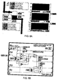
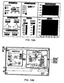
- FIGS 8 - 10 illustrate several exemplary graphical programs to which the present system and method may be applied. Each figure illustrates a block diagram for the program and an associated user interface panel. As described above, the graphical program may execute on one computer, while one or more end users remotely view or interact with the user interface panel of the graphical program from a different computer. Also, an end user may remotely view and/or edit the block diagram of the graphical program. Each graphical program example is briefly described below.
- FIG. 8B simulates a tank control application.
- the associated user interface panel of Figure 8A displays a history of inflow, level, and temperature for the tank control application.
- FIG. 9B simulates an application that uses GPIB instruments to perform a frequency response test on a unit under test (UUT).
- a function generator supplies a sinusoidal input to the UUT (a bandpass filter in this example), and a digital multimeter measures the output voltage of the UUT.
- the block diagram shown in Figure 10B simulates a temperature analysis application. This program reads a simulated temperature, sends an alarm if it is outside a given range, and determines a statistical mean, standard deviation, and histogram of the temperature history.
- the example graphical programs shown in Figures 8 - 10 are directed toward instrumentation, industrial automation, or process control applications.
- the user interface panels for these programs include various controls or display readouts similar to what may appear on a hardware instrument or console.
- program developers and end users working in many different fields may benefit from the system and method described herein, to enable distributed display and/or control of a graphical program user interface for any of various types of applications.
Applications Claiming Priority (5)
| Application Number | Priority Date | Filing Date | Title |
|---|---|---|---|
| US617600 | 1990-11-26 | ||
| US14995099P | 1999-08-19 | 1999-08-19 | |
| US149950P | 1999-08-19 | ||
| US09/617,600 US6802053B1 (en) | 1997-08-18 | 2000-06-13 | Graphical programming system with distributed block diagram execution and front panel display |
| PCT/US2000/022317 WO2001014963A1 (en) | 1999-08-19 | 2000-08-15 | Graphical programming system with distributed block diagram execution and user interface display |
Publications (2)
| Publication Number | Publication Date |
|---|---|
| EP1216441A1 EP1216441A1 (en) | 2002-06-26 |
| EP1216441B1 true EP1216441B1 (en) | 2015-05-27 |
Family
ID=26847176
Family Applications (1)
| Application Number | Title | Priority Date | Filing Date |
|---|---|---|---|
| EP00957450.0A Expired - Lifetime EP1216441B1 (en) | 1999-08-19 | 2000-08-15 | Graphical programming system with distributed block diagram execution and user interface display |
Country Status (4)
| Country | Link |
|---|---|
| US (3) | US6802053B1 (ja) |
| EP (1) | EP1216441B1 (ja) |
| JP (1) | JP4982020B2 (ja) |
| WO (1) | WO2001014963A1 (ja) |
Families Citing this family (122)
| Publication number | Priority date | Publication date | Assignee | Title |
|---|---|---|---|---|
| US7035898B1 (en) | 1997-09-10 | 2006-04-25 | Schneider Automation Inc. | System for programming a factory automation device using a web browser |
| US7743362B2 (en) * | 1998-02-17 | 2010-06-22 | National Instruments Corporation | Automatic generation of application domain specific graphical programs |
| US7937665B1 (en) | 2000-06-13 | 2011-05-03 | National Instruments Corporation | System and method for automatically generating a graphical program to implement a prototype |
| JP2001175574A (ja) * | 1999-12-14 | 2001-06-29 | Fujitsu Ltd | コンソール入出力制御システムおよびコンソール管理装置 |
| US20040205704A1 (en) * | 1999-12-27 | 2004-10-14 | Miller Donald W. | Transparent monitoring system and method for examining an executing program in real time |
| AU4320901A (en) * | 2000-03-13 | 2001-09-24 | Schneider Automation Inc. | A web browser |
| AU2001247743A1 (en) * | 2000-03-24 | 2001-10-08 | Siemens Energy & Automation, Inc. | Industrial automation system graphical programming language storage and transmission |
| US20020066074A1 (en) * | 2000-06-05 | 2002-05-30 | Jabri Mohamed I. | Method and system for developing and executing software applications at an abstract design level |
| US8640027B2 (en) * | 2000-06-13 | 2014-01-28 | National Instruments Corporation | System and method for configuring a hardware device to execute a prototype |
| US7274368B1 (en) * | 2000-07-31 | 2007-09-25 | Silicon Graphics, Inc. | System method and computer program product for remote graphics processing |
| US7313609B1 (en) | 2000-08-09 | 2007-12-25 | Schneider Automation Inc. | Method and apparatus for programming an automation device |
| AUPQ966400A0 (en) * | 2000-08-24 | 2000-09-21 | Xemplex Pty Ltd | Method of graphically defining a formula |
| NZ508052A (en) | 2000-11-09 | 2003-06-30 | Derek Ward | Programmable controller |
| US20020059377A1 (en) * | 2000-11-14 | 2002-05-16 | Jagadish Bandhole | Collaborative computing systems using dynamic computing environments |
| US7370315B1 (en) * | 2000-11-21 | 2008-05-06 | Microsoft Corporation | Visual programming environment providing synchronization between source code and graphical component objects |
| US7000220B1 (en) * | 2001-02-15 | 2006-02-14 | Booth Thomas W | Networked software development environment allowing simultaneous clients with combined run mode and design mode |
| US20020196282A1 (en) * | 2001-06-20 | 2002-12-26 | Washington Jeffrey D. | Collector node for a graphical program |
| US6876368B2 (en) * | 2001-08-14 | 2005-04-05 | National Instruments Corporation | System and method for deploying a graphical program to a PDA device |
| US7594220B2 (en) * | 2001-08-14 | 2009-09-22 | National Instruments Corporation | Configuration diagram with context sensitive connectivity |
| DE10144427A1 (de) * | 2001-09-10 | 2003-04-03 | Siemens Ag | Verfahren zur Verschaltung von Automatisierungsfunktionen in einer Anlage und Verfahren zur Abfrage und Änderung von Verschaltungsinformationen |
| US7257620B2 (en) | 2001-09-24 | 2007-08-14 | Siemens Energy & Automation, Inc. | Method for providing engineering tool services |
| US20030061349A1 (en) * | 2001-09-24 | 2003-03-27 | George Lo | Method and system for collaboratively developing programming code for programmable controllers |
| US8086664B2 (en) | 2001-09-24 | 2011-12-27 | Siemens Industry, Inc. | Method and apparatus for programming programmable controllers and generating configuration data from a centralized server |
| US7134086B2 (en) * | 2001-10-23 | 2006-11-07 | National Instruments Corporation | System and method for associating a block diagram with a user interface element |
| US6993749B2 (en) * | 2002-03-28 | 2006-01-31 | International Business Machines Corporation | Conditional debug monitors |
| GB2388002B (en) * | 2002-04-26 | 2004-05-12 | Oracle Int Corp | Graphical modelling system |
| US7433526B2 (en) * | 2002-04-30 | 2008-10-07 | Hewlett-Packard Development Company, L.P. | Method for compressing images and image sequences through adaptive partitioning |
| US20040031019A1 (en) * | 2002-05-20 | 2004-02-12 | Richard Lamanna | Debugger for a graphical programming environment |
| US8074201B2 (en) * | 2002-07-10 | 2011-12-06 | National Instruments Corporation | Deployment and execution of a program on an embedded device |
| EP1530756B1 (en) * | 2002-07-03 | 2010-09-08 | National Instruments Corporation | Wireless deployment / distributed execution of graphical programs to smart sensors |
| US7185287B2 (en) * | 2002-07-03 | 2007-02-27 | National Instruments Corporation | Wireless deployment / distributed execution of graphical programs to smart sensors |
| US7284234B2 (en) * | 2002-11-06 | 2007-10-16 | Alcatel Canada Inc. | System and method for implementing maintenance functions for a switch |
| US7467018B1 (en) | 2002-11-18 | 2008-12-16 | Rockwell Automation Technologies, Inc. | Embedded database systems and methods in an industrial controller environment |
| US7324912B2 (en) * | 2002-11-25 | 2008-01-29 | Lsi Logic Corporation | Method, system and programming language for device diagnostics and validation |
| JP2004206550A (ja) * | 2002-12-26 | 2004-07-22 | Fanuc Ltd | 数値制御装置 |
| US20040150667A1 (en) * | 2003-01-30 | 2004-08-05 | Dove Andrew Philip | Performing wireless communication in a graphical program |
| US7607098B2 (en) * | 2003-03-14 | 2009-10-20 | Waters Investments Limited | System and method for dynamically controlling operation of rheometric instruments |
| US7885792B2 (en) * | 2003-04-15 | 2011-02-08 | The Mathworks, Inc. | Programming Environment |
| CA2465195C (en) * | 2003-04-28 | 2012-06-19 | Air Products And Chemicals, Inc. | Electrode assembly for the removal of surface oxides by electron attachment |
| US7647578B2 (en) * | 2003-05-15 | 2010-01-12 | National Instruments Corporation | Programmatic creation and management of tasks in a graphical program |
| US7814463B2 (en) * | 2003-05-16 | 2010-10-12 | Oracle International Corporation | User interface debugger for software applications |
| US7624375B2 (en) * | 2003-06-12 | 2009-11-24 | National Instruments Corporation | Automatically configuring a graphical user interface element to bind to a graphical program |
| US7827526B2 (en) * | 2003-06-13 | 2010-11-02 | Analog Devices, Inc. | Stacking and repeating graphical controls |
| US20040268320A1 (en) * | 2003-06-13 | 2004-12-30 | Camille Huin | Graphical computer programming for a digital signal processor |
| US20040268300A1 (en) * | 2003-06-13 | 2004-12-30 | Camille Huin | Graphical computer programming |
| EP1652070A2 (en) * | 2003-07-10 | 2006-05-03 | Computer Associates Think, Inc. | System and method for generating a web-enabled graphical user interface plug-in |
| WO2005008469A2 (en) * | 2003-07-11 | 2005-01-27 | Computer Associates Think, Inc. | System and method for generating a graphical user interface (gui) element |
| WO2005008477A2 (en) * | 2003-07-11 | 2005-01-27 | Computer Associates Think, Inc. | System and method for dynamic generation of a graphical user interface |
| US8875039B2 (en) * | 2003-11-18 | 2014-10-28 | The Mathworks, Inc. | Propagation of characteristics in a graphical model environment |
| US7493595B2 (en) * | 2003-12-19 | 2009-02-17 | The United States Of America As Represented By The Secretary Of The Navy | Multiple-user graphical programming and analysis environment |
| US8793602B2 (en) | 2004-01-15 | 2014-07-29 | The Mathworks, Inc. | System and method for scheduling the execution of model components using model events |
| US8683426B2 (en) | 2005-06-28 | 2014-03-25 | The Mathworks, Inc. | Systems and methods for modeling execution behavior |
| US7434205B1 (en) * | 2004-02-19 | 2008-10-07 | Steenhagen Shawn K | Virtual type interpretation, interaction and detection |
| US7552024B2 (en) | 2004-03-08 | 2009-06-23 | Kelbon Richard G | Circuit board diagnostic operating center |
| US7849440B1 (en) * | 2004-04-16 | 2010-12-07 | The Mathworks, Inc. | Real-time code preview for a model based development process |
| US8397214B2 (en) * | 2004-05-14 | 2013-03-12 | National Instruments Corporation | Generating a hardware description for a programmable hardware element based on a graphical program including multiple physical domains |
| US8453111B2 (en) | 2004-05-14 | 2013-05-28 | National Instruments Corporation | Generating a hardware description for a programmable hardware element based on a graphical program including multiple models of computation |
| US7849412B2 (en) * | 2004-05-21 | 2010-12-07 | Computer Associates Think, Inc. | System and method for generating a web control in a Windows development environment |
| US7565609B2 (en) * | 2004-07-16 | 2009-07-21 | National Instruments Corporation | Synchronizing execution of graphical programs executing on different computer systems |
| US7831680B2 (en) * | 2004-07-16 | 2010-11-09 | National Instruments Corporation | Deterministic communication between graphical programs executing on different computer systems |
| US7725874B2 (en) * | 2004-08-13 | 2010-05-25 | National Instruments Corporation | Combination structure nodes for a graphical program |
| KR100582888B1 (ko) | 2004-09-22 | 2006-05-25 | 삼성전자주식회사 | 정보 공유가 가능한 호스트 기기 및 주변기기, 그의문자정보 공유 방법 및 문자정보 공유 시스템 |
| US7523440B2 (en) * | 2004-11-16 | 2009-04-21 | The Mathworks, Inc. | Dynamic generation of formatted user interfaces in software environments |
| US8122354B1 (en) * | 2005-02-25 | 2012-02-21 | The Mathworks, Inc. | Systems and methods for providing an indicator of detection of input related to an element of a user interface |
| US7706895B2 (en) | 2005-02-25 | 2010-04-27 | Rockwell Automation Technologies, Inc. | Reliable messaging instruction |
| US7565351B1 (en) * | 2005-03-14 | 2009-07-21 | Rockwell Automation Technologies, Inc. | Automation device data interface |
| US20060224250A1 (en) * | 2005-04-01 | 2006-10-05 | Rockwell Automation Technologies, Inc. | Industrial automation interface systems and methods |
| GB2425622A (en) * | 2005-04-27 | 2006-11-01 | Ncapsa Ltd | Programming real-time systems using data flow diagrams |
| US7233830B1 (en) * | 2005-05-31 | 2007-06-19 | Rockwell Automation Technologies, Inc. | Application and service management for industrial control devices |
| EP1902359A1 (en) * | 2005-07-08 | 2008-03-26 | Corizon Limited | Method and apparatus for user interface modification |
| US7761846B2 (en) * | 2005-08-16 | 2010-07-20 | National Instruments Corporation | Graphical programming methods for generation, control and routing of digital pulses |
| US8117588B2 (en) * | 2005-08-18 | 2012-02-14 | National Instruments Corporation | Spatial iteration node for a graphical program |
| US8131529B2 (en) * | 2005-09-01 | 2012-03-06 | Advanced Testing Technologies Inc. | Method and system for simulating test instruments and instrument functions |
| US20080016253A1 (en) * | 2006-07-11 | 2008-01-17 | Boctor Design, Llc | Graphical user interface for navigating and manipulating objects exposed by a host |
| US7954059B2 (en) * | 2006-07-24 | 2011-05-31 | National Instruments Corporation | Automatic conversion of text-based code having function overloading and dynamic types into a graphical program for compiled execution |
| US7975233B2 (en) * | 2006-07-24 | 2011-07-05 | National Instruments Corporation | Automatic conversion of a textual language into a graphical program representation |
| US8108784B2 (en) * | 2006-08-04 | 2012-01-31 | National Instruments Corporation | Configuring icons to represent data transfer functionality |
| US8028241B2 (en) * | 2006-08-04 | 2011-09-27 | National Instruments Corporation | Graphical diagram wires whose appearance represents configured semantics |
| US8028242B2 (en) * | 2006-08-04 | 2011-09-27 | National Instruments Corporation | Diagram with configurable wires |
| US20080126956A1 (en) * | 2006-08-04 | 2008-05-29 | Kodosky Jeffrey L | Asynchronous Wires for Graphical Programming |
| US20080209405A1 (en) * | 2007-02-28 | 2008-08-28 | Microsoft Corporation | Distributed debugging for a visual programming language |
| EP1981245A1 (en) * | 2007-04-13 | 2008-10-15 | Liconic Ag | Method and product for controlling laboratory equipment |
| US8271943B2 (en) * | 2007-04-24 | 2012-09-18 | National Instruments Corporation | Automatically generating a graphical program with a plurality of models of computation |
| US8249845B1 (en) | 2007-05-03 | 2012-08-21 | Advanced Testing Technologies, Inc. | Electro-mechanical system simulator arrangement and method |
| US7996782B2 (en) * | 2007-06-08 | 2011-08-09 | National Instruments Corporation | Data transfer indicator icon in a diagram |
| US7949422B1 (en) * | 2007-06-22 | 2011-05-24 | Vermont Machine Tool Corporation | Machine tool control system |
| EP2012227A1 (de) * | 2007-07-03 | 2009-01-07 | Peter Renner | Programmieroberfläche zum Programmieren von Computern |
| US8020151B2 (en) * | 2007-07-31 | 2011-09-13 | International Business Machines Corporation | Techniques for determining a web browser state during web page testing |
| US20100077260A1 (en) * | 2008-09-22 | 2010-03-25 | Mts Systems Corporation | Testing machine with workflow based test procedure |
| US8819106B1 (en) * | 2008-12-12 | 2014-08-26 | Amazon Technologies, Inc. | Managing distributed execution of programs |
| US8370493B2 (en) * | 2008-12-12 | 2013-02-05 | Amazon Technologies, Inc. | Saving program execution state |
| US8296419B1 (en) | 2009-03-31 | 2012-10-23 | Amazon Technologies, Inc. | Dynamically modifying a cluster of computing nodes used for distributed execution of a program |
| US8321558B1 (en) | 2009-03-31 | 2012-11-27 | Amazon Technologies, Inc. | Dynamically monitoring and modifying distributed execution of programs |
| US8375357B2 (en) * | 2009-05-18 | 2013-02-12 | National Instruments Corporation | Graphical data flow web application repository with version control |
| US8949772B1 (en) | 2009-06-01 | 2015-02-03 | Amazon Technologies, Inc. | Dynamic model based software application development |
| US8423981B2 (en) * | 2009-06-18 | 2013-04-16 | National Instruments Corporation | Compiling a graphical program having a textual language program portion for a real time target |
| US8458653B2 (en) * | 2009-09-29 | 2013-06-04 | National Instruments Corporation | Debugging a graphical program deployed on a programmable hardware element |
| WO2011153361A2 (en) * | 2010-06-02 | 2011-12-08 | Allen Learning Technologies | Device having graphical user interfaces and method for developing multimedia computer applications |
| US9600785B2 (en) * | 2011-01-31 | 2017-03-21 | International Business Machines Corporation | Automatically generated and updated graphical rendering of processes |
| US8612637B2 (en) | 2011-09-25 | 2013-12-17 | National Instruments Corportion | Configuring buffers with timing information |
| US10054913B2 (en) | 2011-12-22 | 2018-08-21 | Leica Biosystems Melbourne Pty Ltd | Laboratory instrument control system |
| US9904258B2 (en) | 2012-05-20 | 2018-02-27 | Mts Systems Corporation | Testing machine with graphical user interface with situational awareness |
| US20140359590A1 (en) | 2013-05-30 | 2014-12-04 | National Instruments Corporation | Development and Deployment of Parallel Floating-Point Math Functionality on a System with Heterogeneous Hardware Components |
| US9182951B1 (en) * | 2013-10-04 | 2015-11-10 | Progress Software Corporation | Multi-ecosystem application platform as a service (aPaaS) |
| US9170922B1 (en) * | 2014-01-27 | 2015-10-27 | Google Inc. | Remote application debugging |
| US20160124744A1 (en) * | 2014-04-03 | 2016-05-05 | Empire Technology Development Llc | Sub-packaging of a packaged application including selection of user-interface elements |
| EP2942678B1 (de) * | 2014-05-08 | 2019-07-17 | dSPACE digital signal processing and control engineering GmbH | Zuweisungsrevolver |
| EP3998758B1 (en) * | 2014-06-18 | 2024-03-20 | Intelligent Platforms, LLC | Apparatus and method for interactions with industrial equipment |
| US9021440B1 (en) | 2014-08-11 | 2015-04-28 | Pmc-Sierra Us, Inc. | System and method for automated test script generation |
| US9652213B2 (en) | 2014-10-23 | 2017-05-16 | National Instruments Corporation | Global optimization and verification of cyber-physical systems using floating point math functionality on a system with heterogeneous hardware components |
| USD781890S1 (en) * | 2014-10-31 | 2017-03-21 | Auto Meter Products, Inc. | Display screen or portion thereof with graphical user interface |
| US10318251B1 (en) * | 2016-01-11 | 2019-06-11 | Altair Engineering, Inc. | Code generation and simulation for graphical programming |
| US10031654B2 (en) * | 2016-04-12 | 2018-07-24 | Honeywell International Inc. | Apparatus and method for generating industrial process graphics |
| US20170323240A1 (en) | 2016-05-06 | 2017-11-09 | General Electric Company | Computing system to control the use of physical state attainment with inspection |
| US11853690B1 (en) * | 2016-05-31 | 2023-12-26 | The Mathworks, Inc. | Systems and methods for highlighting graphical models |
| US20180017300A1 (en) * | 2016-07-15 | 2018-01-18 | Honeywell International Inc. | Refrigeration system operation |
| US10969407B2 (en) | 2016-07-29 | 2021-04-06 | National Instruments Corporation | Soft front panel for concurrent radio frequency measurements |
| WO2018092237A1 (ja) * | 2016-11-17 | 2018-05-24 | 三菱電機株式会社 | プログラムコード生成装置、プログラムコード生成方法及びプログラムコード生成プログラム |
| US11586695B2 (en) * | 2018-02-27 | 2023-02-21 | Elasticsearch B.V. | Iterating between a graphical user interface and plain-text code for data visualization |
| JP2019211988A (ja) * | 2018-06-04 | 2019-12-12 | 日本無線株式会社 | センサー表示手順決定装置、センサー表示装置、センサー表示手順決定プログラム及びセンサー表示手順決定方法 |
| US10812654B2 (en) * | 2018-06-29 | 2020-10-20 | At&T Intellectual Property I, L.P. | Interactive voice response system design, development and testing tool |
| US10997196B2 (en) | 2018-10-30 | 2021-05-04 | Elasticsearch B.V. | Systems and methods for reducing data storage overhead |
Family Cites Families (47)
| Publication number | Priority date | Publication date | Assignee | Title |
|---|---|---|---|---|
| US4849880A (en) | 1985-11-18 | 1989-07-18 | John Fluke Mfg. Co., Inc. | Virtual machine programming system |
| JPH0812206B2 (ja) | 1986-03-07 | 1996-02-07 | ヒューレット・パッカード・カンパニー | 測定器制御装置 |
| US5481740A (en) | 1986-04-14 | 1996-01-02 | National Instruments Corporation | Method and apparatus for providing autoprobe features in a graphical data flow diagram |
| US4827404A (en) | 1986-04-14 | 1989-05-02 | Schlumberger Technology Corporation | Method and system for computer programming |
| US4901221A (en) | 1986-04-14 | 1990-02-13 | National Instruments, Inc. | Graphical system for modelling a process and associated method |
| US5481741A (en) * | 1986-04-14 | 1996-01-02 | National Instruments Corporation | Method and apparatus for providing attribute nodes in a graphical data flow environment |
| US4914568A (en) | 1986-10-24 | 1990-04-03 | National Instruments, Inc. | Graphical system for modelling a process and associated method |
| US5115501A (en) | 1988-11-04 | 1992-05-19 | International Business Machines Corporation | Procedure for automatically customizing the user interface of application programs |
| US7456832B1 (en) | 1989-05-15 | 2008-11-25 | International Business Machines Corporation | Object database-driven interactive shell for a data processing system |
| EP0426909A1 (en) | 1989-11-06 | 1991-05-15 | Heikki Marttila Oy | A method of loading and/or replacing files in a computer software |
| US5109504A (en) | 1989-12-29 | 1992-04-28 | Texas Instruments Incorporated | Graphics program adaptor |
| US5541849A (en) | 1990-04-06 | 1996-07-30 | Lsi Logic Corporation | Method and system for creating and validating low level description of electronic design from higher level, behavior-oriented description, including estimation and comparison of timing parameters |
| US5555201A (en) | 1990-04-06 | 1996-09-10 | Lsi Logic Corporation | Method and system for creating and validating low level description of electronic design from higher level, behavior-oriented description, including interactive system for hierarchical display of control and dataflow information |
| US5283861A (en) * | 1990-08-31 | 1994-02-01 | International Business Machines Corporation | Remote control of a local processor console |
| US5377318A (en) | 1991-02-28 | 1994-12-27 | Hewlett-Packard Company | Line probe diagnostic display in an iconic programming system |
| US5261043A (en) * | 1991-03-12 | 1993-11-09 | Hewlett-Packard Company | Input and output data constraints on iconic devices in an iconic programming system |
| US6313815B1 (en) * | 1991-06-06 | 2001-11-06 | Canon Kabushiki Kaisha | Electron source and production thereof and image-forming apparatus and production thereof |
| US5437464A (en) | 1991-08-30 | 1995-08-01 | Kabushiki Kaisha Sega Enterprises | Data reading and image processing system for CD-ROM |
| US5684980A (en) | 1992-07-29 | 1997-11-04 | Virtual Computer Corporation | FPGA virtual computer for executing a sequence of program instructions by successively reconfiguring a group of FPGA in response to those instructions |
| US5535342A (en) | 1992-11-05 | 1996-07-09 | Giga Operations Corporation | Pld connector for module having configuration of either first PLD or second PLD and reconfigurable bus for communication of two different bus protocols |
| US5497498A (en) | 1992-11-05 | 1996-03-05 | Giga Operations Corporation | Video processing module using a second programmable logic device which reconfigures a first programmable logic device for data transformation |
| US5603043A (en) | 1992-11-05 | 1997-02-11 | Giga Operations Corporation | System for compiling algorithmic language source code for implementation in programmable hardware |
| WO1994015311A1 (en) | 1992-12-28 | 1994-07-07 | Xilinx, Inc. | Method for entering state flow diagrams using schematic editor programs |
| US5544320A (en) * | 1993-01-08 | 1996-08-06 | Konrad; Allan M. | Remote information service access system based on a client-server-service model |
| JPH06230947A (ja) * | 1993-02-07 | 1994-08-19 | Fuji Xerox Co Ltd | プログラム起動装置 |
| EP0626635B1 (en) * | 1993-05-24 | 2003-03-05 | Sun Microsystems, Inc. | Improved graphical user interface with method for interfacing to remote devices |
| US6064409A (en) | 1993-09-22 | 2000-05-16 | National Instruments Corporation | System and method for providing audio probe and debugging features in a graphical data flow program |
| AU5550194A (en) | 1993-09-27 | 1995-04-18 | Giga Operations Corporation | Implementation of a selected instruction set cpu in programmable hardware |
| US5566295A (en) | 1994-01-25 | 1996-10-15 | Apple Computer, Inc. | Extensible simulation system and graphical programming method |
| US5657221A (en) | 1994-09-16 | 1997-08-12 | Medialink Technologies Corporation | Method and apparatus for controlling non-computer system devices by manipulating a graphical representation |
| US5583749A (en) | 1994-11-30 | 1996-12-10 | Altera Corporation | Baseboard and daughtercard apparatus for reconfigurable computing systems |
| US5724074A (en) | 1995-02-06 | 1998-03-03 | Microsoft Corporation | Method and system for graphically programming mobile toys |
| GB9508932D0 (en) | 1995-05-02 | 1995-06-21 | Xilinx Inc | FPGA with parallel and serial user interfaces |
| US5638299A (en) | 1995-06-22 | 1997-06-10 | Miller; Keith | Light weight, self-contained programmable data-acquisition system |
| US5760788A (en) | 1995-07-28 | 1998-06-02 | Microsoft Corporation | Graphical programming system and method for enabling a person to learn text-based programming |
| US5801689A (en) | 1996-01-22 | 1998-09-01 | Extended Systems, Inc. | Hypertext based remote graphic user interface control system |
| US6102965A (en) * | 1996-09-23 | 2000-08-15 | National Instruments Corporation | System and method for providing client/server access to graphical programs |
| US5784275A (en) | 1996-09-23 | 1998-07-21 | National Instruments Corporation | System and method for performing interface independent virtual instrumentation functions in a graphical data flow program |
| JP3336216B2 (ja) * | 1997-02-28 | 2002-10-21 | 松下電工株式会社 | 遠隔mmiシステム |
| JP2873222B2 (ja) * | 1997-05-12 | 1999-03-24 | 川崎重工業株式会社 | ロボット情報処理装置 |
| US6173438B1 (en) | 1997-08-18 | 2001-01-09 | National Instruments Corporation | Embedded graphical programming system |
| US6219628B1 (en) | 1997-08-18 | 2001-04-17 | National Instruments Corporation | System and method for configuring an instrument to perform measurement functions utilizing conversion of graphical programs into hardware implementations |
| US6313851B1 (en) * | 1997-08-27 | 2001-11-06 | Microsoft Corporation | User friendly remote system interface |
| US6138150A (en) * | 1997-09-03 | 2000-10-24 | International Business Machines Corporation | Method for remotely controlling computer resources via the internet with a web browser |
| US6226776B1 (en) | 1997-09-16 | 2001-05-01 | Synetry Corporation | System for converting hardware designs in high-level programming language to hardware implementations |
| US6230307B1 (en) | 1998-01-26 | 2001-05-08 | Xilinx, Inc. | System and method for programming the hardware of field programmable gate arrays (FPGAs) and related reconfiguration resources as if they were software by creating hardware objects |
| US7062718B2 (en) * | 2001-08-14 | 2006-06-13 | National Instruments Corporation | Configuration diagram which graphically displays program relationship |
-
2000
- 2000-06-13 US US09/617,600 patent/US6802053B1/en not_active Expired - Lifetime
- 2000-08-15 JP JP2001519261A patent/JP4982020B2/ja not_active Expired - Lifetime
- 2000-08-15 WO PCT/US2000/022317 patent/WO2001014963A1/en active Application Filing
- 2000-08-15 EP EP00957450.0A patent/EP1216441B1/en not_active Expired - Lifetime
-
2004
- 2004-02-05 US US10/772,518 patent/US8533670B2/en active Active
-
2008
- 2008-06-20 US US12/143,198 patent/US8074203B2/en not_active Expired - Fee Related
Also Published As
| Publication number | Publication date |
|---|---|
| JP4982020B2 (ja) | 2012-07-25 |
| US6802053B1 (en) | 2004-10-05 |
| WO2001014963A1 (en) | 2001-03-01 |
| US8074203B2 (en) | 2011-12-06 |
| EP1216441A1 (en) | 2002-06-26 |
| US20040158812A1 (en) | 2004-08-12 |
| US20090024981A1 (en) | 2009-01-22 |
| US8533670B2 (en) | 2013-09-10 |
| JP2003531414A (ja) | 2003-10-21 |
Similar Documents
| Publication | Publication Date | Title |
|---|---|---|
| EP1216441B1 (en) | Graphical programming system with distributed block diagram execution and user interface display | |
| US7480906B2 (en) | Programmatically analyzing and modifying a remote graphical program via a network | |
| US7076740B2 (en) | System and method for performing rapid control prototyping using a plurality of graphical programs that share a single graphical user interface | |
| US7076411B2 (en) | System and method for performing a hardware-in-the-loop simulation using a plurality of graphical programs that share a single graphical user interface | |
| US7043696B2 (en) | Graphical program system having a single graphical user interface shared by a plurality of graphical programs | |
| US7028222B2 (en) | Target device-specific syntax and semantic analysis for a graphical program | |
| US7159183B1 (en) | System and method for programmatically creating a graphical program | |
| US6880130B2 (en) | Specifying timing and triggering functionality in a graphical program using graphical program nodes | |
| US7210117B2 (en) | System and method for programmatically generating a graphical program in response to program information | |
| US7120876B2 (en) | System and method for programmatically generating a graphical program in response to user input | |
| US6282699B1 (en) | Code node for a graphical programming system which invokes execution of textual code | |
| US7000190B2 (en) | System and method for programmatically modifying a graphical program in response to program information | |
| US7024631B1 (en) | System and method for enabling graphical program polymorphism | |
| US6971065B2 (en) | Automatically configuring a graphical program to publish or subscribe to data | |
| US20030076355A1 (en) | System and method for associating a block diagram with a user interface element | |
| US8479109B2 (en) | Programmatically generating a graphical program in response to user input | |
| US7216334B2 (en) | Self-determining behavior node for use in creating a graphical program | |
| US7543281B2 (en) | Disabling and conditionally compiling graphical code in a graphical program | |
| US20010035879A1 (en) | System and method for programmatically creating nodes in a graphical program with minimal graphical code | |
| US20050251789A1 (en) | Programmatic generation of application domain specific graphical programs | |
| US6874148B1 (en) | System and method for exporting a graphical program to a shared library | |
| US7120877B2 (en) | System and method for creating a graphical program including a plurality of portions to be executed sequentially |
Legal Events
| Date | Code | Title | Description |
|---|---|---|---|
| PUAI | Public reference made under article 153(3) epc to a published international application that has entered the european phase |
Free format text: ORIGINAL CODE: 0009012 |
|
| 17P | Request for examination filed |
Effective date: 20020319 |
|
| AK | Designated contracting states |
Kind code of ref document: A1 Designated state(s): AT BE CH CY DE DK ES FI FR GB GR IE IT LI LU MC NL PT SE |
|
| RIN1 | Information on inventor provided before grant (corrected) |
Inventor name: RICHARDSON, GREG Inventor name: LUICK, DEAN, A. Inventor name: ROGERS, STEVE Inventor name: SHAH, DARSHAN Inventor name: DYE, ROBERT, E. |
|
| 17Q | First examination report despatched |
Effective date: 20031112 |
|
| 17Q | First examination report despatched |
Effective date: 20031112 |
|
| GRAP | Despatch of communication of intention to grant a patent |
Free format text: ORIGINAL CODE: EPIDOSNIGR1 |
|
| INTG | Intention to grant announced |
Effective date: 20150105 |
|
| GRAS | Grant fee paid |
Free format text: ORIGINAL CODE: EPIDOSNIGR3 |
|
| GRAA | (expected) grant |
Free format text: ORIGINAL CODE: 0009210 |
|
| AK | Designated contracting states |
Kind code of ref document: B1 Designated state(s): AT BE CH CY DE DK ES FI FR GB GR IE IT LI LU MC NL PT SE |
|
| REG | Reference to a national code |
Ref country code: GB Ref legal event code: FG4D |
|
| REG | Reference to a national code |
Ref country code: CH Ref legal event code: EP |
|
| REG | Reference to a national code |
Ref country code: AT Ref legal event code: REF Ref document number: 729180 Country of ref document: AT Kind code of ref document: T Effective date: 20150615 |
|
| REG | Reference to a national code |
Ref country code: IE Ref legal event code: FG4D |
|
| REG | Reference to a national code |
Ref country code: DE Ref legal event code: R096 Ref document number: 60048970 Country of ref document: DE Effective date: 20150709 |
|
| REG | Reference to a national code |
Ref country code: AT Ref legal event code: MK05 Ref document number: 729180 Country of ref document: AT Kind code of ref document: T Effective date: 20150527 |
|
| PG25 | Lapsed in a contracting state [announced via postgrant information from national office to epo] |
Ref country code: FI Free format text: LAPSE BECAUSE OF FAILURE TO SUBMIT A TRANSLATION OF THE DESCRIPTION OR TO PAY THE FEE WITHIN THE PRESCRIBED TIME-LIMIT Effective date: 20150527 Ref country code: PT Free format text: LAPSE BECAUSE OF FAILURE TO SUBMIT A TRANSLATION OF THE DESCRIPTION OR TO PAY THE FEE WITHIN THE PRESCRIBED TIME-LIMIT Effective date: 20150928 Ref country code: ES Free format text: LAPSE BECAUSE OF FAILURE TO SUBMIT A TRANSLATION OF THE DESCRIPTION OR TO PAY THE FEE WITHIN THE PRESCRIBED TIME-LIMIT Effective date: 20150527 |
|
| REG | Reference to a national code |
Ref country code: NL Ref legal event code: MP Effective date: 20150527 |
|
| PG25 | Lapsed in a contracting state [announced via postgrant information from national office to epo] |
Ref country code: GR Free format text: LAPSE BECAUSE OF FAILURE TO SUBMIT A TRANSLATION OF THE DESCRIPTION OR TO PAY THE FEE WITHIN THE PRESCRIBED TIME-LIMIT Effective date: 20150828 Ref country code: AT Free format text: LAPSE BECAUSE OF FAILURE TO SUBMIT A TRANSLATION OF THE DESCRIPTION OR TO PAY THE FEE WITHIN THE PRESCRIBED TIME-LIMIT Effective date: 20150527 |
|
| PG25 | Lapsed in a contracting state [announced via postgrant information from national office to epo] |
Ref country code: DK Free format text: LAPSE BECAUSE OF FAILURE TO SUBMIT A TRANSLATION OF THE DESCRIPTION OR TO PAY THE FEE WITHIN THE PRESCRIBED TIME-LIMIT Effective date: 20150527 |
|
| REG | Reference to a national code |
Ref country code: DE Ref legal event code: R097 Ref document number: 60048970 Country of ref document: DE |
|
| PG25 | Lapsed in a contracting state [announced via postgrant information from national office to epo] |
Ref country code: LU Free format text: LAPSE BECAUSE OF FAILURE TO SUBMIT A TRANSLATION OF THE DESCRIPTION OR TO PAY THE FEE WITHIN THE PRESCRIBED TIME-LIMIT Effective date: 20150815 Ref country code: MC Free format text: LAPSE BECAUSE OF FAILURE TO SUBMIT A TRANSLATION OF THE DESCRIPTION OR TO PAY THE FEE WITHIN THE PRESCRIBED TIME-LIMIT Effective date: 20150527 |
|
| REG | Reference to a national code |
Ref country code: CH Ref legal event code: PL |
|
| PLBE | No opposition filed within time limit |
Free format text: ORIGINAL CODE: 0009261 |
|
| STAA | Information on the status of an ep patent application or granted ep patent |
Free format text: STATUS: NO OPPOSITION FILED WITHIN TIME LIMIT |
|
| PG25 | Lapsed in a contracting state [announced via postgrant information from national office to epo] |
Ref country code: IT Free format text: LAPSE BECAUSE OF FAILURE TO SUBMIT A TRANSLATION OF THE DESCRIPTION OR TO PAY THE FEE WITHIN THE PRESCRIBED TIME-LIMIT Effective date: 20150527 Ref country code: LI Free format text: LAPSE BECAUSE OF NON-PAYMENT OF DUE FEES Effective date: 20150831 Ref country code: CH Free format text: LAPSE BECAUSE OF NON-PAYMENT OF DUE FEES Effective date: 20150831 |
|
| 26N | No opposition filed |
Effective date: 20160301 |
|
| REG | Reference to a national code |
Ref country code: IE Ref legal event code: MM4A |
|
| PG25 | Lapsed in a contracting state [announced via postgrant information from national office to epo] |
Ref country code: IE Free format text: LAPSE BECAUSE OF NON-PAYMENT OF DUE FEES Effective date: 20150815 |
|
| REG | Reference to a national code |
Ref country code: FR Ref legal event code: PLFP Year of fee payment: 17 |
|
| PG25 | Lapsed in a contracting state [announced via postgrant information from national office to epo] |
Ref country code: BE Free format text: LAPSE BECAUSE OF FAILURE TO SUBMIT A TRANSLATION OF THE DESCRIPTION OR TO PAY THE FEE WITHIN THE PRESCRIBED TIME-LIMIT Effective date: 20150527 |
|
| PG25 | Lapsed in a contracting state [announced via postgrant information from national office to epo] |
Ref country code: NL Free format text: LAPSE BECAUSE OF FAILURE TO SUBMIT A TRANSLATION OF THE DESCRIPTION OR TO PAY THE FEE WITHIN THE PRESCRIBED TIME-LIMIT Effective date: 20150527 Ref country code: CY Free format text: LAPSE BECAUSE OF FAILURE TO SUBMIT A TRANSLATION OF THE DESCRIPTION OR TO PAY THE FEE WITHIN THE PRESCRIBED TIME-LIMIT Effective date: 20150527 Ref country code: SE Free format text: LAPSE BECAUSE OF FAILURE TO SUBMIT A TRANSLATION OF THE DESCRIPTION OR TO PAY THE FEE WITHIN THE PRESCRIBED TIME-LIMIT Effective date: 20150527 |
|
| REG | Reference to a national code |
Ref country code: FR Ref legal event code: PLFP Year of fee payment: 18 |
|
| REG | Reference to a national code |
Ref country code: FR Ref legal event code: PLFP Year of fee payment: 19 |
|
| PGFP | Annual fee paid to national office [announced via postgrant information from national office to epo] |
Ref country code: DE Payment date: 20190829 Year of fee payment: 20 Ref country code: FR Payment date: 20190822 Year of fee payment: 20 |
|
| PGFP | Annual fee paid to national office [announced via postgrant information from national office to epo] |
Ref country code: GB Payment date: 20190827 Year of fee payment: 20 |
|
| REG | Reference to a national code |
Ref country code: DE Ref legal event code: R071 Ref document number: 60048970 Country of ref document: DE |
|
| REG | Reference to a national code |
Ref country code: GB Ref legal event code: PE20 Expiry date: 20200814 |
|
| PG25 | Lapsed in a contracting state [announced via postgrant information from national office to epo] |
Ref country code: GB Free format text: LAPSE BECAUSE OF EXPIRATION OF PROTECTION Effective date: 20200814 |