EP1215356A2 - Bandanordnung für Türen, Fenster und dergleichen - Google Patents
Bandanordnung für Türen, Fenster und dergleichen Download PDFInfo
- Publication number
- EP1215356A2 EP1215356A2 EP01127505A EP01127505A EP1215356A2 EP 1215356 A2 EP1215356 A2 EP 1215356A2 EP 01127505 A EP01127505 A EP 01127505A EP 01127505 A EP01127505 A EP 01127505A EP 1215356 A2 EP1215356 A2 EP 1215356A2
- Authority
- EP
- European Patent Office
- Prior art keywords
- hinge
- arrangement according
- hinge pin
- assembly
- frame
- Prior art date
- Legal status (The legal status is an assumption and is not a legal conclusion. Google has not performed a legal analysis and makes no representation as to the accuracy of the status listed.)
- Granted
Links
Images
Classifications
-
- E—FIXED CONSTRUCTIONS
- E05—LOCKS; KEYS; WINDOW OR DOOR FITTINGS; SAFES
- E05D—HINGES OR SUSPENSION DEVICES FOR DOORS, WINDOWS OR WINGS
- E05D7/00—Hinges or pivots of special construction
- E05D7/0009—Adjustable hinges
- E05D7/0018—Adjustable hinges at the hinge axis
- E05D7/0027—Adjustable hinges at the hinge axis in an axial direction
-
- E—FIXED CONSTRUCTIONS
- E05—LOCKS; KEYS; WINDOW OR DOOR FITTINGS; SAFES
- E05D—HINGES OR SUSPENSION DEVICES FOR DOORS, WINDOWS OR WINGS
- E05D5/00—Construction of single parts, e.g. the parts for attachment
- E05D5/02—Parts for attachment, e.g. flaps
- E05D5/06—Bent flaps
-
- E—FIXED CONSTRUCTIONS
- E05—LOCKS; KEYS; WINDOW OR DOOR FITTINGS; SAFES
- E05D—HINGES OR SUSPENSION DEVICES FOR DOORS, WINDOWS OR WINGS
- E05D3/00—Hinges with pins
- E05D3/02—Hinges with pins with one pin
- E05D2003/025—Hinges with pins with one pin having three knuckles
-
- E—FIXED CONSTRUCTIONS
- E05—LOCKS; KEYS; WINDOW OR DOOR FITTINGS; SAFES
- E05D—HINGES OR SUSPENSION DEVICES FOR DOORS, WINDOWS OR WINGS
- E05D5/00—Construction of single parts, e.g. the parts for attachment
- E05D5/02—Parts for attachment, e.g. flaps
- E05D5/0215—Parts for attachment, e.g. flaps for attachment to profile members or the like
-
- E—FIXED CONSTRUCTIONS
- E05—LOCKS; KEYS; WINDOW OR DOOR FITTINGS; SAFES
- E05D—HINGES OR SUSPENSION DEVICES FOR DOORS, WINDOWS OR WINGS
- E05D5/00—Construction of single parts, e.g. the parts for attachment
- E05D5/02—Parts for attachment, e.g. flaps
- E05D5/0215—Parts for attachment, e.g. flaps for attachment to profile members or the like
- E05D5/0223—Parts for attachment, e.g. flaps for attachment to profile members or the like with parts, e.g. screws, extending through the profile wall or engaging profile grooves
- E05D5/023—Parts for attachment, e.g. flaps for attachment to profile members or the like with parts, e.g. screws, extending through the profile wall or engaging profile grooves with parts extending through the profile wall
-
- E—FIXED CONSTRUCTIONS
- E05—LOCKS; KEYS; WINDOW OR DOOR FITTINGS; SAFES
- E05D—HINGES OR SUSPENSION DEVICES FOR DOORS, WINDOWS OR WINGS
- E05D9/00—Flaps or sleeves specially designed for making from particular material, e.g. hoop-iron, sheet metal, plastics
-
- E—FIXED CONSTRUCTIONS
- E05—LOCKS; KEYS; WINDOW OR DOOR FITTINGS; SAFES
- E05Y—INDEXING SCHEME ASSOCIATED WITH SUBCLASSES E05D AND E05F, RELATING TO CONSTRUCTION ELEMENTS, ELECTRIC CONTROL, POWER SUPPLY, POWER SIGNAL OR TRANSMISSION, USER INTERFACES, MOUNTING OR COUPLING, DETAILS, ACCESSORIES, AUXILIARY OPERATIONS NOT OTHERWISE PROVIDED FOR, APPLICATION THEREOF
- E05Y2600/00—Mounting or coupling arrangements for elements provided for in this subclass
- E05Y2600/40—Mounting location; Visibility of the elements
- E05Y2600/41—Concealed
-
- E—FIXED CONSTRUCTIONS
- E05—LOCKS; KEYS; WINDOW OR DOOR FITTINGS; SAFES
- E05Y—INDEXING SCHEME ASSOCIATED WITH SUBCLASSES E05D AND E05F, RELATING TO CONSTRUCTION ELEMENTS, ELECTRIC CONTROL, POWER SUPPLY, POWER SIGNAL OR TRANSMISSION, USER INTERFACES, MOUNTING OR COUPLING, DETAILS, ACCESSORIES, AUXILIARY OPERATIONS NOT OTHERWISE PROVIDED FOR, APPLICATION THEREOF
- E05Y2800/00—Details, accessories and auxiliary operations not otherwise provided for
- E05Y2800/26—Form or shape
-
- E—FIXED CONSTRUCTIONS
- E05—LOCKS; KEYS; WINDOW OR DOOR FITTINGS; SAFES
- E05Y—INDEXING SCHEME ASSOCIATED WITH SUBCLASSES E05D AND E05F, RELATING TO CONSTRUCTION ELEMENTS, ELECTRIC CONTROL, POWER SUPPLY, POWER SIGNAL OR TRANSMISSION, USER INTERFACES, MOUNTING OR COUPLING, DETAILS, ACCESSORIES, AUXILIARY OPERATIONS NOT OTHERWISE PROVIDED FOR, APPLICATION THEREOF
- E05Y2900/00—Application of doors, windows, wings or fittings thereof
- E05Y2900/10—Application of doors, windows, wings or fittings thereof for buildings or parts thereof
- E05Y2900/13—Type of wing
- E05Y2900/148—Windows
Definitions
- the invention relates to a belt arrangement of the preamble of Claim 1 corresponding type.
- Such a tape arrangement are used for the pivotable attachment of a an opening optionally closing the wing at the opening delimiting the opening
- Components usually a frame. They include at least a frame hinge part that can be connected to the fixed component, a wing hinge part connectable to the wing and one the two Band parts at least partially penetrating hinge pin, its longitudinal axis defines the pivot axis of the belt.
- hinge function also adds the ability to open the sash in the frame to adjust, i.e. inevitable tolerances that balance out after hanging the sash in the frame opening.
- a belt arrangement consists of a large number of individual parts, when mounting the hinge assembly on the frame or Wings must be put together. The number of items will further increased by the adjustment devices. Often such is for assembly Belt arrangements also a complex processing of the frame or. Sash profiles necessary. Such processing is complex and weak in addition, the mostly thin-walled, not too stable hollow profiles of modern Frame or sash made of metal and / or plastic.
- Hollow profiles are often inserted holding plates, at least by means of spacer bushings are fastened in two opposite walls of the hollow profiles. For this purpose, processing must also be carried out on the profiles, which extend the assembly time.
- the invention is therefore based on the object, a belt arrangement in To simplify assembly.
- the hinge parts, especially the Hinge pin comprises, so that the assembly effort is additionally reduced.
- the assembly preferably includes an adjustment device for the altitude of the wing hinge part relative to the frame hinge part, the Adjustment device from an approximately perpendicular to the adjustment direction, there is an actuator acting on an inclined surface can be formed by a tapered spindle, which is despite the adjustment possibility simple assembly results.
- the height of such a belt arrangement is not disadvantageous Way enlarged by the adjusting device, since the hinge pin bushing can be arranged in a recess of the assembly and the the lower part of the hinge pin.
- the belt arrangement according to the invention is relatively unproblematic, because it would be hidden inside the frame.
- the wing hinge part advantageously lies on an upper edge of the hinge pin bushing on.
- Inclined surface means any surface that is horizontal Level deviates, i.e. does not run perpendicular to the direction of adjustment. Among them are for example spherical surfaces, wedge-shaped inclined planes and concave or understand convex spherical sections, etc.
- the actuator of a tapered spindle and the inclined surface is formed from the underside of the hinge pin bush, the position of the hinge pin bushing can be changed by simply turning the tapered spindle within the frame hinge part and thus the height of the sash hinge part be adjusted.
- the hinge pin bushing Made of plastic and / or metal, making them easier to use For example, can be produced by an injection or casting process.
- the bushing is arranged so that it cannot rotate.
- This anti-rotation device can be designed in a variety of ways. For example, in the simplest case, it can be one along the hinge pin bushing act in the longitudinal direction arranged tongue or groove that engages in a corresponding tongue or groove in the frame hinge part.
- a in a recess of the assembly Hinge pin guide bush is arranged which is the upper part of the hinge pin receives and has a circumferential recess into which Spindle acting perpendicular to the hinge pin for locking the hinge pin guide bush engages, and the wedge and / or the spindle to maximize the bearing length as far below or above as possible with regard to the hinge pin are arranged in the assembly.
- the tapered spindle preferably acts from one of the wing plane or parallel direction to the hinge pin bushing parallel plane a, so that they are slightly open from the rebate area with a wing Turning tool is accessible and with the sash closed, the adjustment device is secured against unwanted access.
- the assembly has a bearing block that can be pivoted about the hinge pin comprises, on which a fastening rail fastened via a bearing lever is provided for pivotable attachment of the wing, the Assembly time "on site” can be further reduced. All that's left is the wing be attached to the bearing block by means of the bearing lever.
- the assembly is advantageously made of aluminum in the extrusion process manufactured.
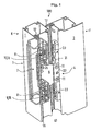
- the belt arrangement according to the invention is designated 100.
- she is used for the pivotable mounting of a wing F, of which only one Section of a vertical casement profile 2 on the vertical frame profile 1 of a fixed frame R can be seen.
- the frame profiles 2.1 of the wing F and the frame R are as metal hollow profiles formed and have a substantially square cross section on. 1 shows the belt arrangement 100 in the pivoted-open state. With the wing F closed, the frame profiles are essentially in one plane, with the front and rear boundary surfaces are each located on the same level.
- a folding area 40 remains between the frame profiles Seals 12, 13 provided folding parts 16 and 17 are covered so that the fold area 40 is also closed when the wing F is closed.
- the seals 12, 13 seal the fold area.
- the real thing Band is housed entirely inside the frame profiles, making it from is not recognizable on the outside when the wing F is closed.
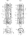
- a hinge pin 15 is attached, the Hinge axis S is determined, around which the wing F can be swung open can (see Fig. 2 to 5).
- the hinge pin 15 is near the inner wall the frame profile 1 arranged. Its dashed in the drawing Support shown represents the frame hinge part 3, which in the form of a Assembly 7 as a prefabricated assembly in the frame profile 1 is used.
- the wing band part designated as a whole by 4 is around Hinge pin 15 pivotable and includes a bearing lever 6, a mounting rail 5 and a bearing block 20.
- the assembly 7 introduced as a whole into the frame profile 1 is by means of Screws 8 on the inner wall of a profile 1, in the illustrated Embodiment, the frame profile attached. These are inside Make appropriate holes in the wall of the profile. Further must in the inner wall of the profile 1 recesses 18, 19 available be to the still to be described adjusting device or hinge pin bushing to be able to operate. Between the screws 8 or their bores in the inner wall of the frame profile 1 Rectangular recess 21 is provided as an opening for the Bearing lever 6 and the bearing block 20 for pivoting around the hinge pin 15 serves.
- the bearing lever 6 is by means of screws 11 and an associated one Pressure plate 22 in the fastening rail 5 of the wing hinge part 4 screwed parallel to the wing plane.
- the mounting rail 5 itself is screwed to the inner wall of the wing profile 2 by means of further screws 23.
- the frame hinge part is 3 or the assembly 7 inside hollow, so that a swivel range for the Bearing lever 6 or the appropriate fastening means 24, for Example in the form of screws, attached bearing block 20 is formed.
- the Module 7 is designed as an extruded aluminum part and has one in substantially rectangular cross-section, but for its stiffening at the corners there are bent angles 25. additionally the corners 25 are present since the cross section of the assembly 7 is adapted to the cross section of the hollow frame profile, which corresponding has folds formed in the corners. The assembly fills accordingly in cross section of the entire cavity of the profile, whereby a particularly good power distribution is achieved.
- the recess 42 lies, as seen in the length of the fastening block 7, in this approximately in the center and includes the walls 26 and 27.
- the hinge pin 15 accommodated in the assembly 7 is therefore of the areas 28 and 29 which are located at the bottom and at the top in the assembly 7, surround.
- the bearing block 20 has an approximately L-shaped shape, on one of which End it has a through-hole through which the hinge pin 15 runs, and at the other end the bearing lever 6 via the fastening means 24 is screwed on, for example.
- the end that carries the bearing lever 6 is slightly beveled. Since the bearing lever 6 itself is approximately flattened V-shape, results when pivoting the bearing block 20 together with the bearing lever 6 attached to it requires less space, so that the recesses 42 and 21 can be as small as possible, so that the hollow profile is hardly weakened.
- the wall 27 has a cross section in approximately triangular thickened shape, the position of the maximum Thickening is in the corner between the wall 27 and the wall 26 and a corresponding through-bore for receiving the hinge pin 15 having.
- This thickening is particularly advantageous because it is in this area the mounting screws are included.
- the assembly also enables 7 an introduction of forces over a larger area so that a Force transmission into the relatively thin-walled, not too stable hollow profiles is avoided.
- the hinge pin 15 is in the through hole 30 at its upper end by a guide bush 31 added, which extends over the entire area 29 and over a Spindle 10, which extends radially around the guide bush Recess engages 32, is locked.
- the hinge pin 15 has on his top end a head 41 that is a little wider than the bore 30, so that the hinge pin rests on the bottom of this head and into the hole 30 is struck for attachment.
- the assembly 7 has four holes 37 in the course of its wall 27 the fastening screws 8 and two threaded bores 19, 18 for the locking spindle 10 or for the adjusting spindle to be described 9th
- the hinge pin is in a hinge pin bushing 33 added, which with an edge 34 on the lower Edge of the recess 21 rests.
- the hinge pin bushing 33 forms an inclined surface 35 in its base, to which the tapered spindle 9 with its beveled area for height adjustment is applied.
- Fig. 3 is the state of the minimum height adjustment shown
- Fig. 4 the state of a maximum height adjustment is shown.
- the tapered spindle 9 in the case of the minimum Height adjustment is hardly turned in and therefore only with its tip protrudes into the bore 30 so that it does not the hinge pin sleeve 33 moves up. 4, however, the cone spindle 9 is complete, i.e. as far as possible through the threaded hole in the hinge pin hole 30 screwed in. Therefore, the hinge pin bushing is at the top postponed.
- the inclined plane of the tapered spindle gives way from the horizontal by an angle ⁇ , the angle ⁇ preferably is between 25 ° and 45 °, in particular 30 °. It is cheap also if the inclined surface is also designed as a wedge, which in opposite direction, i.e. from the horizontal up to the Angle ⁇ is chamfered. This results in a particularly good interaction of the two adjoining surfaces, which creates a good Adjustability is made possible and there is also less wear Band parts and better power absorption results.
- the wing hinge part 4 lies with its bearing block 20 on which the bearing lever 6 is attached, with the interposition of a bearing disc 36 the edge 34 of the hinge pin bushing 33.
- the band arrangement according to the invention was hidden above with reference to a Volume described, in which it can be used advantageously.
- the described design of the frame hinge parts, the hinge parts etc. can also be used advantageously in other belt arrangements.
Landscapes
- Engineering & Computer Science (AREA)
- Mechanical Engineering (AREA)
- Hinges (AREA)
Abstract
Description
- Fig. 1
- eine perspektivische Ansicht einer erfindungsgemäßen Bandanordnung an einem Abschnitt eines Rahmens bzw. Flügels, wobei unsichtbare Linien teilweise gestrichelt dargestellt sind;
- Fig. 2
- eine Draufsicht von oben in Längsrichtung eines erfindungsgemäßen, höhenverstellbaren Rahmenbandteils;
- Fig. 3
- das Rahmenbandteil aus Fig. 2 im Schnitt entlang der Linie I-I;
- Fig. 4
- das Rahmenbandteil aus Fig. 3, bei dem eine Höhenverstellung vorgenommen wurde und
- Fig. 5
- eine Draufsicht entlang der Längsrichtung des Rahmenbandteils aus Fig. 4 im Schnitt entlang der Linie II-II.
Claims (18)
- Bandanordnung für Türen, Fenster und dergleichen
mit einem an dem feststehenden Rahmen (R) der Tür, des Fensters oder dergleichen zu befestigenden Rahmenbandteil (3),
mit einem an dem Flügel (F) der Tür, des Fensters oder dergleichen zu befestigenden Flügelbandteil (4),
und mit einem vertikalen, die Scharnierteile der Bandteile (3,4) durchgreifenden Bandbolzen (15) zur scharnierartigen verschwenkbaren Verbindung der Bandteile,
dadurch gekennzeichnet, daß zumindest eines der Bandteile (3,4) als Teil einer vorgefertigten Baugruppe (7) im Inneren des Rahmens ausgebildet ist. - Bandanordnung nach Anspruch 1, dadurch gekennzeichnet, daß die Baugruppe (7) die Scharnierteile, insbesondere den Bandbolzen (15) umfaßt.
- Bandanordnung nach Anspruch 1 oder 2, dadurch gekennzeichnet, daß die Baugruppe (7) eine Verstelleinrichtung für die Höhenlage des Flügelbandteils (4) gegenüber dem Rahmenbandteil (3) umfaßt, wobei die Verstelleinrichtung eine etwa senkrecht zur Verstellrichtung verstellbare, auf eine Schrägfläche (35) einwirkende Betätigungseinrichtung umfaßt.
- Bandanordnung nach Anspruch 3, dadurch gekennzeichnet, daß die Betätigungseinrichtung eine Kegelspindel (9) umfaßt.
- Bandanordnung nach einem der vorhergehenden Ansprüche, dadurch gekennzeichnet, daß die Baugruppe eine Bandbolzenbüchse (33), die in einer Ausnehmung (30) angeordnet ist und den unteren Teil des Bandbolzens (15) aufnimmt, umfaßt.
- Bandanordnung nach Anspruch 5, dadurch gekennzeichnet, daß die Schrägfläche (35) an der Bandbolzenbüchse (33) ausgebildet wird.
- Bandanordnung nach einem der Ansprüche 3 bis 6, dadurch gekennzeichnet, daß die Schrägfläche (35) am unteren Ende der Bandbolzenbüchse (33) ausgebildet ist.
- Bandanordnung nach einem der Ansprüch 5 bis 7, dadurch gekennzeichnet, daß das Flügelbandteil (4) auf einem oberen Rand (34) der Bandbolzenbüchse (33) aufliegt.
- Bandanordnung nach einem der Ansprüche 5 bis 8, dadurch gekennzeichnet, daß die Bandbolzenbüchse (33) in der Baugruppe (7) verdrehsicher angeordnet ist.
- Bandanordnung nach einem der Ansprüche 4 bis 9, dadurch gekennzeichnet, daß die Kegelspindel (9) eine schiefe Ebene aufweist, die von der Horizontalen um einen Winkel (α) abweicht.
- Bandanordnung nach Anspruch 10, dadurch gekennzeichnet, daß der Winkel (α) vorzugsweise zwischen 25° und 45°, insbesondere 30° beträgt.
- Bandanordnung nach einem der Ansprüche 6 bis 11, dadurch gekennzeichnet, daß die Schrägfläche (35) ebenfalls als Keil ausgebildet ist, wobei der Keilwinkel so gewählt ist, daß sich die Schrägfläche (35) linienförmig auf der Kegelspindel abstützt.
- Bandanordnung nach einem der vorhergehenden Ansprüche, dadurch gekennzeichnet, daß in der Ausnehmung (30) der Baugruppe (7) eine Bandbolzenführungsbüchse (31) angeordnet ist, die den oberen Teil des Bandbolzens aufnimmt und eine umlaufende Ausnehmung (32) aufweist, in die eine senkrecht zum Bandbolzen (15) wirkende Spindel (10) zum Arretieren der Bandbolzenführungsbüchse (31) eingreift.
- Bandanordnung nach Anspruch 13, dadurch gekennzeichnet, daß der Keil (9) und/oder die Spindel (10) zur Lagerlängenmaximierung möglichst weit unten bzw. oben bezüglich des Bandbolzens (15) in der Baugruppe (7) angeordnet sind.
- Bandanordnung nach einem der Ansprüche 3 bis 14, dadurch gekennzeichnet, daß die Kegelspindel (9) aus einer von der Flügelebene oder dazu parallelen Ebene abweichenden Richtung auf die Bandbolzenbüchse (33) einwirkt.
- Bandanordnung nach einem der vorhergehenden Ansprüche, dadurch gekennzeichnet, daß die Baugruppe (7) einen um den Bandbolzen (15) verschwenkbaren Lagerblock (20) umfaßt, an welchem eine über einen Lagerhebel (6) befestigte Befestigungsschiene (5) zur schwenkbaren Befestigung des Flügels (F) vorgesehen ist.
- Bandanordnung nach einem der vorhergehenden Ansprüche, dadurch gekennzeichnet, daß die Baugruppe (7) einen im wesentlichen dem Rahmen entsprechenden Querschnitt aufweist und hohl ist.
- Bandanordnung nach einem der vorhergehenden Ansprüche, dadurch gekennzeichnet, daß die Baugruppe (7) im Strangpreßverfahren aus Aluminium hergestellt ist.
Applications Claiming Priority (2)
| Application Number | Priority Date | Filing Date | Title |
|---|---|---|---|
| DE20021404U | 2000-12-18 | ||
| DE20021404U DE20021404U1 (de) | 2000-12-18 | 2000-12-18 | Bandanordnung für Türen, Fenster u.dgl. |
Publications (3)
| Publication Number | Publication Date |
|---|---|
| EP1215356A2 true EP1215356A2 (de) | 2002-06-19 |
| EP1215356A3 EP1215356A3 (de) | 2006-04-05 |
| EP1215356B1 EP1215356B1 (de) | 2008-04-23 |
Family
ID=7950219
Family Applications (1)
| Application Number | Title | Priority Date | Filing Date |
|---|---|---|---|
| EP20010127505 Expired - Lifetime EP1215356B1 (de) | 2000-12-18 | 2001-11-17 | Bandanordnung für Türen, Fenster und dergleichen |
Country Status (2)
| Country | Link |
|---|---|
| EP (1) | EP1215356B1 (de) |
| DE (2) | DE20021404U1 (de) |
Cited By (1)
| Publication number | Priority date | Publication date | Assignee | Title |
|---|---|---|---|---|
| WO2005021910A1 (de) * | 2003-08-21 | 2005-03-10 | Abb Patent Gmbh | Befestigungsbock |
Families Citing this family (1)
| Publication number | Priority date | Publication date | Assignee | Title |
|---|---|---|---|---|
| DE102005062613B3 (de) | 2005-12-23 | 2006-12-07 | Simonswerk, Gmbh | Tür, insbesondere für Trennwandsysteme |
Citations (1)
| Publication number | Priority date | Publication date | Assignee | Title |
|---|---|---|---|---|
| EP0300292A1 (de) | 1987-07-20 | 1989-01-25 | OTLAV S.p.A. | In drei Richtungen verstellbares Scharnier, insbesondere für Tür- und Fensterrahmen |
Family Cites Families (7)
| Publication number | Priority date | Publication date | Assignee | Title |
|---|---|---|---|---|
| DE3511776A1 (de) * | 1985-03-30 | 1986-10-09 | Friedrich 8500 Nürnberg Puchtler | Tueraufhaengevorrichtung |
| DE29509161U1 (de) * | 1995-06-09 | 1996-10-17 | Niemann, Hans Dieter, 50169 Kerpen | Drehband für Fensterflügel |
| DE29514335U1 (de) * | 1995-09-07 | 1997-01-09 | Breuer & Schmitz, 42719 Solingen | Stahlzargen-Scharnierkonstruktion |
| DE29809448U1 (de) * | 1998-04-03 | 1998-10-08 | Fischer, Dieter, 15741 Motzen | Verschwindscharnier |
| DE29814666U1 (de) * | 1998-08-14 | 1999-12-16 | Schörghuber Spezialtüren GmbH & Co Betriebs-KG, 84539 Ampfing | Verankerungsvorrichtung zum Verankern eines Türscharniers in einer Zarge und mit einer solchen Verankerungsvorrichtung versehene Tür |
| NL1011982C2 (nl) * | 1999-05-06 | 2000-11-07 | Metaalwarenindustrie Van Ijken | Verstelbare paumelle. |
| DE29922023U1 (de) * | 1999-12-15 | 2001-04-26 | Dr. Hahn GmbH & Co. KG, 41189 Mönchengladbach | Baugruppe mit einem Band für Türen, Fenster o.dgl. |
-
2000
- 2000-12-18 DE DE20021404U patent/DE20021404U1/de not_active Expired - Lifetime
-
2001
- 2001-11-17 DE DE50113884T patent/DE50113884D1/de not_active Expired - Lifetime
- 2001-11-17 EP EP20010127505 patent/EP1215356B1/de not_active Expired - Lifetime
Patent Citations (1)
| Publication number | Priority date | Publication date | Assignee | Title |
|---|---|---|---|---|
| EP0300292A1 (de) | 1987-07-20 | 1989-01-25 | OTLAV S.p.A. | In drei Richtungen verstellbares Scharnier, insbesondere für Tür- und Fensterrahmen |
Cited By (1)
| Publication number | Priority date | Publication date | Assignee | Title |
|---|---|---|---|---|
| WO2005021910A1 (de) * | 2003-08-21 | 2005-03-10 | Abb Patent Gmbh | Befestigungsbock |
Also Published As
| Publication number | Publication date |
|---|---|
| DE20021404U1 (de) | 2002-05-02 |
| EP1215356A3 (de) | 2006-04-05 |
| EP1215356B1 (de) | 2008-04-23 |
| DE50113884D1 (de) | 2008-06-05 |
Similar Documents
| Publication | Publication Date | Title |
|---|---|---|
| EP1816295B1 (de) | Insektenschutztür | |
| EP3805498A1 (de) | Beschlag und duschabtrennung | |
| EP0754831B1 (de) | Flügelseitiges Ecklagerbeschlagteil für Drehkippfenster | |
| EP1017920B1 (de) | Beschlag zur drehlagerung eines fenster- oder türflügels | |
| EP1215357B1 (de) | Bandanordnung für Türen, Fenster und dergleichen | |
| EP0784956A1 (de) | Duschabtrennung | |
| DE3104973A1 (de) | "aufschraubband, insbesondere fuer schwere fenster- oder tuerfluegel mit kunststoffprofilen" | |
| DE19522222C2 (de) | Scharnierbeschlag für ein Fenster, eine Tür od. dgl. | |
| DE2524268C3 (de) | Scharnier für Profil- oder Rohrrahmen von Türen o.dgl | |
| EP1577476B1 (de) | Scharnier zur drehbaren Halterung einer Tür oder eines Fensters an einem Rahmen | |
| DE19944549B4 (de) | Verschwindscharnier | |
| DE60010806T2 (de) | Verdeckter Öffnungsbeschlag für Drehflügeltür oder -Fenster | |
| DE29620246U1 (de) | Band für Türen oder Fenster | |
| EP0874123B1 (de) | Beschlag zur Lagerung des Drehflügels eines Fensters oder einer Tür | |
| EP1215356B1 (de) | Bandanordnung für Türen, Fenster und dergleichen | |
| DE3001070A1 (de) | Eckgelenk fuer drehkippfenster, -tueren o.dgl. | |
| DE102005014394B4 (de) | Flügel einer Tür oder eines Fensters | |
| DE60101813T2 (de) | Ecklager für Türen, Fenster oder dergleichen | |
| DE19918283B4 (de) | Tür- oder Fensterdrehband | |
| EP1659246A1 (de) | Scharnierbeschlag für Fensterläden | |
| DE20012351U1 (de) | Fenster oder Tür mit Entlastungseinrichtung | |
| DE9301655U1 (de) | Scharnierbeschlag | |
| EP1653030B1 (de) | Scharnier mit wenigstens zwei Scharnierteilen zur Anordnung in Zusammenwirken mit einem Trag- und Aufnahmeelement | |
| EP4045745B1 (de) | Ecklager | |
| EP0616106B1 (de) | Fenster oder Tür mit Scharnierbeschlag |
Legal Events
| Date | Code | Title | Description |
|---|---|---|---|
| PUAI | Public reference made under article 153(3) epc to a published international application that has entered the european phase |
Free format text: ORIGINAL CODE: 0009012 |
|
| AK | Designated contracting states |
Kind code of ref document: A2 Designated state(s): AT BE CH CY DE DK ES FI FR GB GR IE IT LI LU MC NL PT SE TR |
|
| AX | Request for extension of the european patent |
Free format text: AL;LT;LV;MK;RO;SI |
|
| PUAL | Search report despatched |
Free format text: ORIGINAL CODE: 0009013 |
|
| AK | Designated contracting states |
Kind code of ref document: A3 Designated state(s): AT BE CH CY DE DK ES FI FR GB GR IE IT LI LU MC NL PT SE TR |
|
| AX | Request for extension of the european patent |
Extension state: AL LT LV MK RO SI |
|
| 17P | Request for examination filed |
Effective date: 20060915 |
|
| AKX | Designation fees paid |
Designated state(s): BE DE IT SE TR |
|
| 17Q | First examination report despatched |
Effective date: 20070221 |
|
| GRAP | Despatch of communication of intention to grant a patent |
Free format text: ORIGINAL CODE: EPIDOSNIGR1 |
|
| GRAS | Grant fee paid |
Free format text: ORIGINAL CODE: EPIDOSNIGR3 |
|
| GRAA | (expected) grant |
Free format text: ORIGINAL CODE: 0009210 |
|
| AK | Designated contracting states |
Kind code of ref document: B1 Designated state(s): BE DE IT SE TR |
|
| REF | Corresponds to: |
Ref document number: 50113884 Country of ref document: DE Date of ref document: 20080605 Kind code of ref document: P |
|
| REG | Reference to a national code |
Ref country code: SE Ref legal event code: TRGR |
|
| PLBE | No opposition filed within time limit |
Free format text: ORIGINAL CODE: 0009261 |
|
| STAA | Information on the status of an ep patent application or granted ep patent |
Free format text: STATUS: NO OPPOSITION FILED WITHIN TIME LIMIT |
|
| PGFP | Annual fee paid to national office [announced via postgrant information from national office to epo] |
Ref country code: SE Payment date: 20081107 Year of fee payment: 8 |
|
| 26N | No opposition filed |
Effective date: 20090126 |
|
| PGFP | Annual fee paid to national office [announced via postgrant information from national office to epo] |
Ref country code: TR Payment date: 20091023 Year of fee payment: 9 |
|
| PGFP | Annual fee paid to national office [announced via postgrant information from national office to epo] |
Ref country code: IT Payment date: 20091116 Year of fee payment: 9 |
|
| EUG | Se: european patent has lapsed | ||
| PGFP | Annual fee paid to national office [announced via postgrant information from national office to epo] |
Ref country code: BE Payment date: 20091130 Year of fee payment: 9 Ref country code: DE Payment date: 20091130 Year of fee payment: 9 |
|
| BERE | Be: lapsed |
Owner name: DR. HAHN G.M.B.H. & CO. KG Effective date: 20101130 |
|
| PG25 | Lapsed in a contracting state [announced via postgrant information from national office to epo] |
Ref country code: SE Free format text: LAPSE BECAUSE OF NON-PAYMENT OF DUE FEES Effective date: 20091118 |
|
| PG25 | Lapsed in a contracting state [announced via postgrant information from national office to epo] |
Ref country code: BE Free format text: LAPSE BECAUSE OF NON-PAYMENT OF DUE FEES Effective date: 20101130 |
|
| REG | Reference to a national code |
Ref country code: DE Ref legal event code: R119 Ref document number: 50113884 Country of ref document: DE Effective date: 20110601 Ref country code: DE Ref legal event code: R119 Ref document number: 50113884 Country of ref document: DE Effective date: 20110531 |
|
| PG25 | Lapsed in a contracting state [announced via postgrant information from national office to epo] |
Ref country code: IT Free format text: LAPSE BECAUSE OF NON-PAYMENT OF DUE FEES Effective date: 20101117 |
|
| PG25 | Lapsed in a contracting state [announced via postgrant information from national office to epo] |
Ref country code: TR Free format text: LAPSE BECAUSE OF NON-PAYMENT OF DUE FEES Effective date: 20101117 |
|
| PG25 | Lapsed in a contracting state [announced via postgrant information from national office to epo] |
Ref country code: DE Free format text: LAPSE BECAUSE OF NON-PAYMENT OF DUE FEES Effective date: 20110531 |