EP1213628A1 - Method for adjusting the oscillation frequence of a sprung balance for a mechanical timepiece - Google Patents
Method for adjusting the oscillation frequence of a sprung balance for a mechanical timepiece Download PDFInfo
- Publication number
- EP1213628A1 EP1213628A1 EP00204369A EP00204369A EP1213628A1 EP 1213628 A1 EP1213628 A1 EP 1213628A1 EP 00204369 A EP00204369 A EP 00204369A EP 00204369 A EP00204369 A EP 00204369A EP 1213628 A1 EP1213628 A1 EP 1213628A1
- Authority
- EP
- European Patent Office
- Prior art keywords
- hairspring
- oscillation
- frequency
- machining
- balance
- Prior art date
- Legal status (The legal status is an assumption and is not a legal conclusion. Google has not performed a legal analysis and makes no representation as to the accuracy of the status listed.)
- Withdrawn
Links
Images
Classifications
-
- G—PHYSICS
- G04—HOROLOGY
- G04D—APPARATUS OR TOOLS SPECIALLY DESIGNED FOR MAKING OR MAINTAINING CLOCKS OR WATCHES
- G04D7/00—Measuring, counting, calibrating, testing or regulating apparatus
- G04D7/10—Measuring, counting, calibrating, testing or regulating apparatus for hairsprings of balances
-
- G—PHYSICS
- G04—HOROLOGY
- G04B—MECHANICALLY-DRIVEN CLOCKS OR WATCHES; MECHANICAL PARTS OF CLOCKS OR WATCHES IN GENERAL; TIME PIECES USING THE POSITION OF THE SUN, MOON OR STARS
- G04B17/00—Mechanisms for stabilising frequency
- G04B17/04—Oscillators acting by spring tension
- G04B17/06—Oscillators with hairsprings, e.g. balance
- G04B17/066—Manufacture of the spiral spring
Definitions
- the present invention relates to a frequency adjustment method of a balance spring fitted to a mechanical timepiece.
- the regulator assembly of a watch movement will be briefly described below in using Figures 1 and 2 attached.
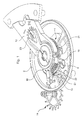
- this regulator assembly includes a balance spring 1 associated with a balance 2.
- the balance spring is connected to axis 4 of the balance by means of a ferrule 6.
- the outer end 8 of the hairspring is fixed to a stud 10 secured to the balance bridge 12 (rooster).
- the balance-spring oscillation is maintained by the escape wheel 14 engaged with the train of the movement.
- the object of the present invention is to overcome the drawbacks mentioned above by proposing a method for adjusting the frequency of a balance spring efficient, inexpensive and simplifying the construction of the assembly regulator.
- the invention relates to a method for adjusting the frequency of oscillation of a balance-spring according to the steps mentioned in claim 1, in which we use laser machining of the balance spring to reduce the torque elasticity of the latter until reaching a reference elastic torque substantially corresponding to the reference frequency for the oscillation of the sprung balance.
- knowledge of the elastic reference torque is not necessary since the adjustment can be done in one or more successive steps by measuring the frequency of the assembled balance spring.
- the hairspring ready for mounting for a given length between the points of attachment to the ferrule 6 and to the pin 10 has an elastic torque greater than the reference elastic torque above.
- laser machining has the effect of reducing the elastic torque of the spiral, as will be explained below in more detail.
- the adjustment of the oscillation frequency of the balance spring can be carried out during a preliminary stage, preceding the mounting of this balance spring in a watch movement.
- a presetting can be carried out according to the invention in this preliminary step and a fine adjustment, also to using a laser beam, is carried out once the balance spring is mounted in the watch movement to allow precise adjustment of the oscillation frequency of this balance spring in real operating conditions and thus ensure a exact movement of the watch movement.
- the regulator assembly preferably no longer comprises pins racket.
- the problems of gait variation according to the position of the movement, due to the passage of the outer spiral spiral between the pins, are eliminated.
- the present invention is particularly suitable for factory or watch workshop adjustment and may prove to be complex for implementation by an after-sales service workshop carrying out the traditional checks and necessary repairs following possible damage caused to the timepiece.
- the balance spring 1, 2 is assembled and the outer end 22 of the balance spring is attached to a stud 10 of a watch movement (not shown).
- the assembled balance spring can be mounted in a device specifically used to the process of the invention. In the latter case, the stud 10 belongs to the device specific or is replaced by an equivalent fixing means.
- the hairspring is produced with an elastic torque greater than one reference elastic torque corresponding to a reference frequency for the oscillation of the balance-spring.
- the frequency is measured of balance-spring oscillation, this frequency then being greater than the frequency reference.
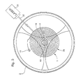
- a laser device 30 providing a laser beam 32 for machining or processing the hairspring 1.
- the adjustment of the frequency of the regulator assembly is adjusted neither using racket pins, nor using screws or small masses arranged on the balance 2.
- the present invention does not exclude the possibility of providing means for variation of the balance inertia to allow fine adjustments after adjustment initial in the factory by means of the method according to the invention. According to this process, laser machining of hairspring 1 so as to reduce its elastic torque until that it is substantially equal to the above-mentioned reference elastic torque.
- the oscillation frequency is finely adjusted to using the laser device 30 as a function of one or more frequency measurements oscillation.
- the program for controlling the laser device 30 and its movement relative to the balance spring can include a single step of machining or processing based on an initial frequency measurement, using an algorithm based on an analytical or empirical model, or a combination both.
- numerous control variants of the laser device within the framework of the implementation of the method according to the invention are possible.
- the laser beam 32 to modify at least superficially the structure of hairspring 1 in at least one of its parts, in particular on a section of its external turn 24.
- This machining has firstly, the function of varying the elastic modulus E of the balance spring by lowering it up to a value for which the elastic torque of this hairspring corresponds to the value reference. Indeed, the oscillation frequency being proportional to the root square of the elastic torque M of the hairspring, and this torque being proportional to the modulus elasticity E, a reduction in this modulus therefore makes it possible to decrease the frequency oscillation of the regulator assembly.
- laser machining can also be carried out on several spiral turns, along sections of varying sizes defined in particular according to the access to these turns by the laser beam.
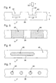
- a second embodiment of the method shown schematically in Figure 4, it is planned to partially decrease the height H of the ribbon 36 forming this hairspring.
- This decrease in height is expected only along of sections L1, L2 of the ribbon 36, which defines open cutouts 40 along the upper or lower edge of this ribbon. These cuts can vary in length and in number.
- the elastic torque of hairspring 1 being proportional to the height of the ribbon 36, an at least partial reduction in this height makes it possible to reduce this torque and therefore the frequency of oscillation of the balance spring.
- laser machining is therefore used primarily to remove material and provision is made to focus the beam 32 on the region of machining of the ribbon 36.
- the laser is arranged so that the beam 32 is substantially perpendicular to the general plane of the hairspring allowing machining either the upper surface, that is, the lower surface of the hairspring.
- This last variant makes it possible to act over a larger area for the laser beam, but has the disadvantage that the laser beam can also reach the turn preceding that which is being machined.
- This second mode of implementation of the method easily makes it possible to machine several spiral turns, in particular in the preferred variant.
- the thickness of the ribbon 36 forming the hairspring 1 is planned to at least partially reduce the thickness of the ribbon 36 forming the hairspring 1.
- This reduction in thickness in the zones 44 is carried out using of a laser beam.
- This laser machining is preferably carried out on the turn 24 of the balance spring, but it is also possible to machine other turns by orienting this laser beam obliquely relative to the plane of the balance spring.
- the zones 44 pass through from top to bottom. Their width can be variable, as can the number of machined zones provided. It is also possible to provide a succession of machining of lines operated by paths along a vertical axis of the laser beam. The decrease in frequency comes from the fact that the elastic torque of the balance spring varies according to the cube thickness (e 3 ) of the ribbon forming the balance spring.
- Figures 6 and 7 show two machining variants on the face lateral 46 of the hairspring 1.
- the area 48 is oblong. This zone 48 forms a recess in the tape 36 without reaching the upper and lower surfaces of this one. Thus, the appearance of the hairspring seen from above is not affected.
- the areas 50 form a succession of circular recesses.
- laser machining may create through openings.
Abstract
Description
La présente invention concerne un procédé de réglage de la fréquence
d'oscillation d'un balancier-spiral équipant une pièce d'horlogerie mécanique.
L'ensemble régulateur d'un mouvement horloger sera décrit brièvement ci-après à
l'aide des figures 1 et 2 annexées. De manière classique, cet ensemble régulateur
comprend un spiral 1 associé à un balancier 2. Le spiral est relié à l'axe 4 du balancier
au moyen d'une virole 6. L'extrémité extérieure 8 du spiral est fixée à un piton 10
solidaire du pont de balancier 12 (coq). L'oscillation du balancier-spiral est entretenue
par la roue d'échappement 14 en prise avec le rouage du mouvement.The present invention relates to a frequency adjustment method
of a balance spring fitted to a mechanical timepiece.
The regulator assembly of a watch movement will be briefly described below in
using Figures 1 and 2 attached. Conventionally, this regulator assembly
includes a balance spring 1 associated with a
Pour régler la fréquence d'oscillation du balancier-spiral, il est prévu de
manière classique deux goupilles 16 et 17 fixées à une raquette 18 susceptible d'être
déplacée en rotation par exemple au moyen d'une vis excentrique 20. Ainsi, en variant
la position des goupilles, on varie la longueur active du spiral. Le couple élastique du
spiral étant inversement proportionnel à la longueur active du spiral, la fréquence
d'oscillation du balancier-spiral est sensiblement inversement proportionnelle à la
racine carrée de cette longueur active. Ainsi, pour régler la fréquence de marche du
mouvement horloger, il est prévu en général dans l'art antérieur un système de
réglage comprenant une raquette et des goupilles entre lesquelles passe la partie
terminale 22 de la spire extérieure 24 de ce spiral 1.To adjust the oscillation frequency of the balance spring, it is planned to
conventionally two
On notera qu'il existe d'autres systèmes de réglage agissant notamment sur le
moment d'inertie du balancier 2. Tous ces moyens nécessitent l'agencement d'un
certain nombre de composants destinés au réglage de la fréquence d'oscillation du
balancier-spiral.It will be noted that there are other adjustment systems which act in particular on the
moment of inertia of the
De plus, dans le cas représenté aux figures 1 et 2, l'ajustement des deux
goupilles 16 et 17 est relativement délicat. On constate souvent que selon la position
du mouvement dans l'espace, l'action des goupilles est plus ou moins efficace de
sorte que la longueur active du spiral varie selon cette position. Ceci est bien sûr
néfaste pour la marche de la pièce d'horlogerie et donc pour l'exactitude de l'heure ou
intervalle de temps affiché par celle-ci.In addition, in the case shown in Figures 1 and 2, the adjustment of the two
Le but de la présente invention consiste à pallier les inconvénients susmentionnés en proposant un procédé de réglage de la fréquence d'un balancier-spiral efficace, peu onéreux et permettant de simplifier la construction de l'ensemble régulateur.The object of the present invention is to overcome the drawbacks mentioned above by proposing a method for adjusting the frequency of a balance spring efficient, inexpensive and simplifying the construction of the assembly regulator.
A cet effet, l'invention a pour objet un procédé de réglage de la fréquence
d'oscillation d'un balancier-spiral selon les étapes mentionnées à la revendication 1,
au cours desquelles on utilise un usinage au laser du spiral pour diminuer le couple
élastique de ce dernier jusqu'à atteindre un couple élastique de référence
correspondant sensiblement à la fréquence de référence pour l'oscillation du
balancier-spiral. On notera ici que la connaissance du couple élastique de référence
n'est pas nécessaire étant donné que le réglage peut être fait en une ou plusieurs
étapes successives en mesurant la fréquence du balancier-spiral assemblé. Par
contre, dans le cadre de la présente invention, il est nécessaire que le spiral prêt au
montage, pour une longueur donnée entre les points de fixation à la virole 6 et au
piton 10, présente un couple élastique supérieur au couple élastique de référence
susmentionné. En effet, l'usinage laser a pour effet de diminuer le couple élastique du
spiral, comme cela sera exposé ci-après de manière plus détaillée.To this end, the invention relates to a method for adjusting the frequency
of oscillation of a balance-spring according to the steps mentioned in claim 1,
in which we use laser machining of the balance spring to reduce the torque
elasticity of the latter until reaching a reference elastic torque
substantially corresponding to the reference frequency for the oscillation of the
sprung balance. It will be noted here that knowledge of the elastic reference torque
is not necessary since the adjustment can be done in one or more
successive steps by measuring the frequency of the assembled balance spring. Through
against, in the context of the present invention, it is necessary that the hairspring ready for
mounting, for a given length between the points of attachment to the
On notera que le réglage de la fréquence d'oscillation du balancier-spiral peut être effectuée lors d'une étape préliminaire, précédent le montage de ce balancier-spiral dans un mouvement horloger. Dans une variante, un pré-réglage peut être effectué selon l'invention dans cette étape préliminaire et un réglage fin, également à l'aide d'un faisceau laser, est effectué une fois le balancier-spiral monté dans le mouvement horloger pour permettre de régler précisément la fréquence d'oscillation de ce balancier-spiral en situation réelle de fonctionnement et ainsi assurer une marche exacte du mouvement horloger.Note that the adjustment of the oscillation frequency of the balance spring can be carried out during a preliminary stage, preceding the mounting of this balance spring in a watch movement. In a variant, a presetting can be carried out according to the invention in this preliminary step and a fine adjustment, also to using a laser beam, is carried out once the balance spring is mounted in the watch movement to allow precise adjustment of the oscillation frequency of this balance spring in real operating conditions and thus ensure a exact movement of the watch movement.
Grâce aux caractéristiques de la présente invention, aucun élément spécifique au réglage de la fréquence d'oscillation du balancier-spiral n'est nécessaire. En particulier, l'ensemble régulateur ne comporte de préférence plus de goupilles de raquette. Ainsi, les problèmes de variation de marche selon la position du mouvement, due au passage de la spire extérieure du spiral entre les goupilles, sont éliminés. On notera toutefois qu'il est possible, dans un mode de réalisation particulier, d'équiper le balancier de moyens de réglage fin de son moment d'inertie de manière à permettre un réglage ultérieur après une certaine période de fonctionnement du mouvement horloger. En effet, la présente invention est particulièrement adaptée à un réglage en usine ou atelier d'horlogerie et peut s'avérer complexe pour une mise en oeuvre par un atelier de service après-vente effectuant les contrôles traditionnels et les réparations nécessaires suite à des dommages éventuels causés à la pièce d'horlogerie.Thanks to the features of the present invention, no specific element to adjust the oscillation frequency of the balance spring is not necessary. In in particular, the regulator assembly preferably no longer comprises pins racket. Thus, the problems of gait variation according to the position of the movement, due to the passage of the outer spiral spiral between the pins, are eliminated. Note however that it is possible, in one embodiment particular, to equip the balance wheel with means for fine adjustment of its moment of inertia so as to allow further adjustment after a certain period of operation of the watch movement. Indeed, the present invention is particularly suitable for factory or watch workshop adjustment and may prove to be complex for implementation by an after-sales service workshop carrying out the traditional checks and necessary repairs following possible damage caused to the timepiece.
La présente invention sera décrite plus en détail à l'aide des figures annexées, données à titre d'exemples nullement limitatifs, et dans lesquelles :
- les figures 1 et 2, déjà décrites, représentent un ensemble régulateur de l'art antérieur équipé d'une raquette avec ses deux goupilles;
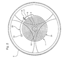
- la figure 3 est une vue simplifiée de dessus d'un balancier-spiral selon l'invention fixé à un piton;
- la figure 4 montre schématiquement un mode d'usinage laser du spiral dans le cadre du procédé selon l'invention, et
- les figures 5 à 7 représentent schématiquement trois variantes d'un autre mode de mise en oeuvre du procédé selon l'invention.
- Figures 1 and 2, already described, show a regulator assembly of the prior art equipped with a racket with its two pins;
- Figure 3 is a simplified top view of a balance spring according to the invention attached to a stud;
- FIG. 4 schematically shows a laser machining mode of the hairspring within the framework of the method according to the invention, and
- Figures 5 to 7 schematically represent three variants of another embodiment of the method according to the invention.
A l'aide de la figure 3, on décrira de manière générale le procédé selon
l'invention. Le balancier-spiral 1, 2 est assemblé et l'extrémité externe 22 du spiral est
fixée à un piton 10 d'un mouvement horloger (non représenté). On notera que le
balancier-spiral assemblé peut être monté dans un dispositif servant spécifiquement
au procédé de l'invention. Dans ce dernier cas, le piton 10 appartient au dispositif
spécifique ou est remplacé par un moyen de fixation équivalent.With the help of FIG. 3, the process according to general will be described
the invention. The
Selon l'invention, le spiral est fabriqué avec un couple élastique supérieur à un couple élastique de référence correspondant à une fréquence de référence pour l'oscillation du balancier-spiral.According to the invention, the hairspring is produced with an elastic torque greater than one reference elastic torque corresponding to a reference frequency for the oscillation of the balance-spring.
A l'aide de moyens connus de l'homme du métier, on mesure la fréquence
d'oscillation du balancier-spiral, cette fréquence étant alors supérieure à la fréquence
de référence. Pour régler cette fréquence d'oscillation et l'ajuster au moins
sensiblement à la fréquence de référence, il est prévu selon l'invention d'utiliser un
dispositif laser 30 fournissant un faisceau laser 32 pour l'usinage ou le traitement du
spiral 1. Ainsi, dans le cadre de la présente invention, le réglage de la fréquence
d'oscillation de l'ensemble régulateur est réglée ni à l'aide de goupilles de raquette, ni
à l'aide de vis ou petites masses agencées sur le balancier 2. Toutefois, comme déjà
mentionné, la présente invention n'écarte pas la possibilité de prévoir des moyens de
variation de l'inertie du balancier pour permettre des réglages fins après un réglage
initial en usine au moyen du procédé selon l'invention. Selon ce procédé, on effectue
un usinage laser du spiral 1 de manière à diminuer son couple élastique jusqu'à ce
qu'il soit sensiblement égal au couple élastique de référence susmentionné.Using means known to those skilled in the art, the frequency is measured
of balance-spring oscillation, this frequency then being greater than the frequency
reference. To set this oscillation frequency and adjust it at least
substantially at the reference frequency, it is provided according to the invention to use a
Dans le cadre du procédé selon l'invention, il est possible de prévoir au moins
deux étapes de réglage à l'aide du faisceau laser, à savoir une première étape hors
de la pièce d'horlogerie permettant de régler grossièrement la fréquence d'oscillation
tout en s'assurant de rester supérieure à la fréquence de référence. Ensuite, dans
une seconde étape intervenant après le montage du balancier-spiral dans la pièce
d'horlogerie à laquelle il est destiné, on ajuste finement la fréquence d'oscillation à
l'aide du dispositif laser 30 en fonction d'une ou plusieurs mesures de la fréquence
d'oscillation. In the context of the method according to the invention, it is possible to provide at least
two adjustment steps using the laser beam, i.e. a first step outside
of the timepiece allowing rough adjustment of the oscillation frequency
while ensuring that it remains above the reference frequency. Then in
a second step occurring after mounting the balance spring in the room
of the timepiece for which it is intended, the oscillation frequency is finely adjusted to
using the
Le programme de commande du dispositif laser 30 et de son mouvement
relatif avec le balancier-spiral peut comporter une seule étape d'usinage ou de
traitement en fonction d'une mesure initiale de la fréquence, en utilisant un algorithme
établi sur la base d'un modèle analytique ou empirique, ou encore d'une combinaison
des deux. Dans une variante plus sophistiquée, il est possible de prévoir une boucle
de rétroaction, le traitement où l'usinage laser étant effectué par une succession
d'étapes entre lesquelles une mesure de ladite fréquence d'oscillation est effectuée.
Dans ce cas, on peut approcher rapidement la valeur de référence en peu d'étapes,
par exemple une ou deux, et finir le réglage fin par d'autres étapes ultérieures dans
lesquelles l'usinage laser n'a qu'un faible impact sur le couple élastique du spiral.
Ainsi, de nombreuses variantes de commande du dispositif laser dans le cadre de la
mise en oeuvre du procédé selon l'invention sont possibles.The program for controlling the
Dans un premier mode de réalisation, il est prévu à l'aide du faisceau laser 32
de modifier au moins superficiellement la structure du spiral 1 dans au moins une de
ses parties, notamment sur un tronçon de sa spire externe 24. Cet usinage a
premièrement pour fonction de varier le module d'élasticité E du spiral en l'abaissant
jusqu'à une valeur pour laquelle le couple élastique de ce spiral correspond à la valeur
de référence. En effet, la fréquence d'oscillation étant proportionnelle à la racine
carrée du couple élastique M du spiral, et ce couple étant proportionnel au module
d'élasticité E, une diminution de ce module permet donc de diminuer la fréquence
d'oscillation de l'ensemble régulateur. On notera que l'usinage laser peut également
être effectué sur plusieurs spires du spiral, le long de tronçons de grandeurs variables
définies notamment en fonction de l'accès à ces spires par le faisceau laser.In a first embodiment, it is provided using the
Selon un deuxième mode de mise en oeuvre du procédé, représenté
schématiquement à la figure 4, il est prévu de diminuer partiellement la hauteur H du
ruban 36 formant ce spiral. Cette diminution d'hauteur est prévue seulement le long
de tronçons L1, L2 du ruban 36, ce qui définit des découpures ouvertes 40 le long du
bord supérieur ou inférieur de ce ruban. Ces découpures peuvent varier en longueur
et en nombre. Le couple élastique du spiral 1 étant proportionnel à la hauteur du
ruban 36, une diminution au moins partielle de cette hauteur permet de réduire ce
couple et donc la fréquence d'oscillation du balancier-spiral.According to a second embodiment of the method, shown
schematically in Figure 4, it is planned to partially decrease the height H of the
On notera ici que l'usinage laser sert donc premièrement à enlever de la
matière et il est prévu de focaliser le faisceau 32 sur la région d'usinage du ruban 36.
Selon une variante préférée, le laser est agencé de manière que le faisceau 32 est
sensiblement perpendiculaire au plan général du spiral permettant un usinage soit de
la surface supérieure, soit de la surface inférieure du spiral. Toutefois, dans une autre
variante, il est prévu d'incliner le dispositif 30 de sorte que le faisceau laser 32 est
orienté obliquement relativement au ruban 36. Cette dernière variante permet d'agir
sur une plus grande surface pour le faisceau laser, mais présente l'inconvénient que
le faisceau laser peut aussi atteindre la spire précédent celle qui est usinée. Ce
deuxième mode de mise en oeuvre du procédé permet aisément d'usiner plusieurs
spires du spiral, en particulier dans la variante préférée.It should be noted here that laser machining is therefore used primarily to remove
material and provision is made to focus the
Selon un troisième mode de mise en oeuvre du procédé représenté à la figure
5, il est prévu de diminuer au moins partiellement l'épaisseur du ruban 36 formant le
spiral 1. Cette diminution d'épaisseur dans les zones 44 est effectuée à l'aide d'un
faisceau laser. Cet usinage laser est effectué de préférence sur la spire 24 du spiral,
mais il est également possible d'usiner d'autres spires en orientant ce faisceau laser
obliquement relativement au plan du spiral. A la figure 5, les zones 44 sont
traversantes de haut en bas. Leur largeur peut être variable, tout comme le nombre
de zones usinées prévu. Il est également possible de prévoir une succession
d'usinage de lignes opérées par des trajets selon un axe verticale du faisceau laser.
La diminution de fréquence provient du fait que le couple élastique du spiral varie
selon l'épaisseur au cube (e3) du ruban formant le spiral.According to a third embodiment of the method shown in FIG. 5, it is planned to at least partially reduce the thickness of the
Aux figures 6 et 7 sont représentées deux variantes d'usinage sur la face
latérale 46 du spiral 1. A la figure 6, la zone 48 est oblongue. Cette zone 48 forme un
évidement dans le ruban 36 sans atteindre les surfaces supérieure et inférieure de
celui-ci. Ainsi, l'aspect du spiral vu de dessus n'est pas affecté. A la figure 7, les zones
50 forment une succession d'évidements circulaires.Figures 6 and 7 show two machining variants on the
On notera finalement que dans les réalisations représentées aux figures 6 et 7, il est possible que l'usinage au laser crée des ouvertures traversantes.Finally, note that in the embodiments shown in FIGS. 6 and 7, laser machining may create through openings.
Claims (7)
Priority Applications (1)
| Application Number | Priority Date | Filing Date | Title |
|---|---|---|---|
| EP00204369A EP1213628A1 (en) | 2000-12-07 | 2000-12-07 | Method for adjusting the oscillation frequence of a sprung balance for a mechanical timepiece |
Applications Claiming Priority (1)
| Application Number | Priority Date | Filing Date | Title |
|---|---|---|---|
| EP00204369A EP1213628A1 (en) | 2000-12-07 | 2000-12-07 | Method for adjusting the oscillation frequence of a sprung balance for a mechanical timepiece |
Publications (1)
| Publication Number | Publication Date |
|---|---|
| EP1213628A1 true EP1213628A1 (en) | 2002-06-12 |
Family
ID=8172390
Family Applications (1)
| Application Number | Title | Priority Date | Filing Date |
|---|---|---|---|
| EP00204369A Withdrawn EP1213628A1 (en) | 2000-12-07 | 2000-12-07 | Method for adjusting the oscillation frequence of a sprung balance for a mechanical timepiece |
Country Status (1)
| Country | Link |
|---|---|
| EP (1) | EP1213628A1 (en) |
Cited By (6)
| Publication number | Priority date | Publication date | Assignee | Title |
|---|---|---|---|---|
| WO2012007460A1 (en) * | 2010-07-16 | 2012-01-19 | Eta Sa Manufacture Horlogère Suisse | Method for adjusting the oscillation frequency, the inertia or the balance of a mobile component in a movement or in a balance and spring assembly of a timepiece |
| CN102528282A (en) * | 2010-12-08 | 2012-07-04 | 上海康比利仪表有限公司 | Laser hairspring welding instrument |
| EP3181939A1 (en) * | 2015-12-18 | 2017-06-21 | CSEM Centre Suisse d'Electronique et de Microtechnique SA - Recherche et Développement | Method for manufacturing a hairspring with predetermined stiffness by adding material |
| EP3181938A1 (en) * | 2015-12-18 | 2017-06-21 | CSEM Centre Suisse d'Electronique et de Microtechnique SA - Recherche et Développement | Method for manufacturing a hairspring with a predetermined stiffness by removing material |
| EP3181940A1 (en) * | 2015-12-18 | 2017-06-21 | CSEM Centre Suisse d'Electronique et de Microtechnique SA - Recherche et Développement | Method for manufacturing a hairspring with a predetermined stiffness by localised removal of material |
| EP3416001B1 (en) * | 2017-06-13 | 2022-04-13 | Patek Philippe SA Genève | Method for manufacturing an oscillator with flexible pivot |
Citations (2)
| Publication number | Priority date | Publication date | Assignee | Title |
|---|---|---|---|---|
| US3673376A (en) * | 1968-08-26 | 1972-06-27 | Jean Claude Kullmann | Method for attaching the inner end of a balance spring to its collet |
| CH1283368A4 (en) * | 1968-08-27 | 1972-10-31 | Fabriques De Spiraux Reunis So | Method for obtaining an oscillating balance-spring of desired frequency |
-
2000
- 2000-12-07 EP EP00204369A patent/EP1213628A1/en not_active Withdrawn
Patent Citations (2)
| Publication number | Priority date | Publication date | Assignee | Title |
|---|---|---|---|---|
| US3673376A (en) * | 1968-08-26 | 1972-06-27 | Jean Claude Kullmann | Method for attaching the inner end of a balance spring to its collet |
| CH1283368A4 (en) * | 1968-08-27 | 1972-10-31 | Fabriques De Spiraux Reunis So | Method for obtaining an oscillating balance-spring of desired frequency |
Cited By (26)
| Publication number | Priority date | Publication date | Assignee | Title |
|---|---|---|---|---|
| WO2012007460A1 (en) * | 2010-07-16 | 2012-01-19 | Eta Sa Manufacture Horlogère Suisse | Method for adjusting the oscillation frequency, the inertia or the balance of a mobile component in a movement or in a balance and spring assembly of a timepiece |
| CN103003760A (en) * | 2010-07-16 | 2013-03-27 | Eta瑞士钟表制造股份有限公司 | Method for adjusting the oscillation frequency, the inertia or the balance of a mobile component in a movement or in a balance and spring assembly of a timepiece |
| JP2013542402A (en) * | 2010-07-16 | 2013-11-21 | ウーテーアー・エス・アー・マニファクチュール・オロロジェール・スイス | Method for oscillating frequency adjustment and / or inertia adjustment and / or balance correction of a movable component of a watch movement or a spring-temp assembly of a watch |
| CN103003760B (en) * | 2010-07-16 | 2015-04-15 | Eta瑞士钟表制造股份有限公司 | Method for adjusting the oscillation frequency, the inertia or the balance of a mobile component in a movement or in a balance and spring assembly of a timepiece |
| RU2556322C2 (en) * | 2010-07-16 | 2015-07-10 | Эта Са Мануфактюр Орложэр Сюис | Adjustment of oscillation frequency and/or adjustment of moment of inertia and/or balancing of moving components of chronometer or chronometer balance-spiral assy |
| US9436162B2 (en) | 2010-07-16 | 2016-09-06 | Eta Sa Manufacture Horlogere Suisse | Method for adjusting the oscillation frequency and/or adjusting the inertia and/or balancing of a movable timepiece movement component or of a timepiece spring balance assembly |
| CN102528282A (en) * | 2010-12-08 | 2012-07-04 | 上海康比利仪表有限公司 | Laser hairspring welding instrument |
| CN102528282B (en) * | 2010-12-08 | 2014-04-09 | 上海康比利仪表有限公司 | Laser hairspring welding instrument |
| CN106896700A (en) * | 2015-12-18 | 2017-06-27 | 瑞士电子显微技术研究与开发中心股份有限公司 | The method that the hairspring of predetermined stiffness is manufactured by local removal material |
| EP3181938B1 (en) | 2015-12-18 | 2019-02-20 | CSEM Centre Suisse d'Electronique et de Microtechnique SA - Recherche et Développement | Method for manufacturing a hairspring with a predetermined stiffness by removing material |
| EP3181940A1 (en) * | 2015-12-18 | 2017-06-21 | CSEM Centre Suisse d'Electronique et de Microtechnique SA - Recherche et Développement | Method for manufacturing a hairspring with a predetermined stiffness by localised removal of material |
| US20170176941A1 (en) * | 2015-12-18 | 2017-06-22 | Csem Centre Suisse D'electronique Et De Microtechnique Sa - Recherche Et Developpement | Method for fabrication of a balance spring of a predetermined stiffness by local removal of material |
| EP3181939A1 (en) * | 2015-12-18 | 2017-06-21 | CSEM Centre Suisse d'Electronique et de Microtechnique SA - Recherche et Développement | Method for manufacturing a hairspring with predetermined stiffness by adding material |
| CN106896708A (en) * | 2015-12-18 | 2017-06-27 | 瑞士电子显微技术研究与开发中心股份有限公司 | For the method for the hairspring by removing material manufacture predetermined stiffness |
| CN106997170A (en) * | 2015-12-18 | 2017-08-01 | 瑞士电子显微技术研究与开发中心股份有限公司 | Method for the hairspring by increasing material manufacture predetermined thickness |
| EP3181940B1 (en) | 2015-12-18 | 2019-02-06 | CSEM Centre Suisse d'Electronique et de Microtechnique SA - Recherche et Développement | Method for manufacturing a hairspring with a predetermined stiffness by localised removal of material |
| EP3181939B1 (en) | 2015-12-18 | 2019-02-20 | CSEM Centre Suisse d'Electronique et de Microtechnique SA - Recherche et Développement | Method for manufacturing a hairspring with predetermined stiffness by adding material |
| EP3181938A1 (en) * | 2015-12-18 | 2017-06-21 | CSEM Centre Suisse d'Electronique et de Microtechnique SA - Recherche et Développement | Method for manufacturing a hairspring with a predetermined stiffness by removing material |
| US10324417B2 (en) | 2015-12-18 | 2019-06-18 | CSEM Centre Suisse d'Electronique et de Microtechnique SA-Recherche et Développement | Method for fabrication of a balance spring of a predetermined stiffness by removal of material |
| US10324418B2 (en) | 2015-12-18 | 2019-06-18 | CSEM Centre Suisse d'Electronique et de Microtechnique SA-Recherche et Développement | Method for fabrication of a balance spring of predetermined thickness through the addition of material |
| US10338528B2 (en) | 2015-12-18 | 2019-07-02 | Csem Centre Suisse D'electronique Et De Microtechnique Sa—Recherche Et Developpement | Method for fabrication of a balance spring of a predetermined stiffness by local removal of material |
| CN106997170B (en) * | 2015-12-18 | 2019-10-15 | 瑞士电子显微技术研究与开发中心股份有限公司 | Method for manufacturing the balance spring of predetermined thickness by increasing material |
| CN106896700B (en) * | 2015-12-18 | 2019-10-15 | 瑞士电子显微技术研究与开发中心股份有限公司 | The method for removing material by part to manufacture the balance spring of predetermined stiffness |
| CN106896708B (en) * | 2015-12-18 | 2019-10-15 | 瑞士电子显微技术研究与开发中心股份有限公司 | Method for manufacturing the balance spring of predetermined stiffness by removal material |
| CN110376871A (en) * | 2015-12-18 | 2019-10-25 | 瑞士电子显微技术研究与开发中心股份有限公司 | Method for manufacturing the balance spring of predetermined stiffness by removal material |
| EP3416001B1 (en) * | 2017-06-13 | 2022-04-13 | Patek Philippe SA Genève | Method for manufacturing an oscillator with flexible pivot |
Similar Documents
| Publication | Publication Date | Title |
|---|---|---|
| WO2012066094A2 (en) | Method of setting the oscillation frequency of a clockwork subassembly | |
| CH703935A2 (en) | Body balance spring regulator. | |
| JP2002214368A (en) | Method for adjusting oscillation frequency of spring balance for mechanical timepiece | |
| EP3227754A1 (en) | Clock balance/hairspring assembly | |
| CH700260B1 (en) | Spiral balance without setting item. | |
| EP1213628A1 (en) | Method for adjusting the oscillation frequence of a sprung balance for a mechanical timepiece | |
| WO2016016456A2 (en) | Device for assembling and adjusting a balance spring | |
| EP3430479A1 (en) | Device for a timepiece, timepiece movement and timepiece comprising a device of said type | |
| EP3502788B1 (en) | Standalone device for adjusting the active length of a hairspring | |
| EP2917792B1 (en) | Method for balancing a clockwork balance wheel-hairspring assembly | |
| CH713409B1 (en) | Balance wheel for balance-spring of the thermocompensated type, balance-spring of the thermocompensated type, movement and timepiece. | |
| FR3048792B1 (en) | DEVICE FOR WATCHMAKING PART, CLOCK MOVEMENT AND TIMEPIECE COMPRISING SUCH A DEVICE | |
| EP3391154B1 (en) | Oscillating system for timepiece | |
| EP1079284A1 (en) | Clockwork movement | |
| CH701155B1 (en) | Balance spiral type mechanical oscillator for e.g. wrist watch, has balance and spiral, which are made of non-magnetic material such as diamond, where material possesses very low thermal expansion coefficient | |
| EP3647883A1 (en) | Timepiece balance | |
| CH715513A2 (en) | Balance of a timepiece. | |
| WO2018015071A1 (en) | Method for setting the movement of a timepiece | |
| CH340188A (en) | Balance wheel with adjustable moment of inertia | |
| EP4286962A1 (en) | Timepiece regulating member comprising a regulator assembly provided with locking means | |
| CH719743A2 (en) | CLOCK REGULATING ORGAN INCLUDING A RACKET SYSTEM PROVIDED WITH LOCKING MEANS | |
| EP4286961A1 (en) | Timepiece regulator provided with a precision index-assembly | |
| CH719744A2 (en) | Watchmaking regulating body equipped with a precision racket system | |
| CH719238A2 (en) | Balance with inertia adjustment. | |
| FR3048793A1 (en) | MICRO MECHANISM WITH POSITION ADJUSTMENT, WATCHMAKING MOVEMENT AND TIMEPIECE COMPRISING SUCH A MECHANISM |
Legal Events
| Date | Code | Title | Description |
|---|---|---|---|
| PUAI | Public reference made under article 153(3) epc to a published international application that has entered the european phase |
Free format text: ORIGINAL CODE: 0009012 |
|
| AK | Designated contracting states |
Kind code of ref document: A1 Designated state(s): AT BE CH CY DE DK ES FI FR GB GR IE IT LI LU MC NL PT SE TR |
|
| AX | Request for extension of the european patent |
Free format text: AL;LT;LV;MK;RO;SI |
|
| 17P | Request for examination filed |
Effective date: 20021212 |
|
| AKX | Designation fees paid |
Designated state(s): CH DE LI |
|
| STAA | Information on the status of an ep patent application or granted ep patent |
Free format text: STATUS: THE APPLICATION HAS BEEN WITHDRAWN |
|
| RAP1 | Party data changed (applicant data changed or rights of an application transferred) |
Owner name: ETA SA MANUFACTURE HORLOGERE SUISSE |
|
| 18W | Application withdrawn |
Effective date: 20030227 |