EP3181939A1 - Method for manufacturing a hairspring with predetermined stiffness by adding material - Google Patents
Method for manufacturing a hairspring with predetermined stiffness by adding material Download PDFInfo
- Publication number
- EP3181939A1 EP3181939A1 EP15201337.1A EP15201337A EP3181939A1 EP 3181939 A1 EP3181939 A1 EP 3181939A1 EP 15201337 A EP15201337 A EP 15201337A EP 3181939 A1 EP3181939 A1 EP 3181939A1
- Authority
- EP
- European Patent Office
- Prior art keywords
- hairspring
- stiffness
- predetermined
- spiral
- dimensions
- Prior art date
- Legal status (The legal status is an assumption and is not a legal conclusion. Google has not performed a legal analysis and makes no representation as to the accuracy of the status listed.)
- Granted
Links
- 238000004519 manufacturing process Methods 0.000 title claims abstract description 32
- 239000000463 material Substances 0.000 title claims abstract description 23
- 238000000034 method Methods 0.000 title claims description 37
- 229910052710 silicon Inorganic materials 0.000 claims description 10
- 239000010703 silicon Substances 0.000 claims description 10
- 239000000203 mixture Substances 0.000 claims description 8
- 238000000708 deep reactive-ion etching Methods 0.000 claims description 6
- 239000000919 ceramic Substances 0.000 claims description 4
- 238000000151 deposition Methods 0.000 claims description 4
- 239000011521 glass Substances 0.000 claims description 4
- 238000003486 chemical etching Methods 0.000 claims description 3
- 239000002184 metal Substances 0.000 claims description 3
- 229910001092 metal group alloy Inorganic materials 0.000 claims description 3
- 238000012986 modification Methods 0.000 abstract description 2
- 230000004048 modification Effects 0.000 abstract description 2
- 235000012431 wafers Nutrition 0.000 description 15
- XUIMIQQOPSSXEZ-UHFFFAOYSA-N Silicon Chemical group [Si] XUIMIQQOPSSXEZ-UHFFFAOYSA-N 0.000 description 11
- VYPSYNLAJGMNEJ-UHFFFAOYSA-N Silicium dioxide Chemical compound O=[Si]=O VYPSYNLAJGMNEJ-UHFFFAOYSA-N 0.000 description 8
- 230000002093 peripheral effect Effects 0.000 description 8
- 229910021421 monocrystalline silicon Inorganic materials 0.000 description 7
- 229910021420 polycrystalline silicon Inorganic materials 0.000 description 7
- 239000003607 modifier Substances 0.000 description 5
- 229910021417 amorphous silicon Inorganic materials 0.000 description 4
- 238000005530 etching Methods 0.000 description 4
- 239000002210 silicon-based material Substances 0.000 description 4
- 230000008901 benefit Effects 0.000 description 3
- 238000005229 chemical vapour deposition Methods 0.000 description 3
- 239000006185 dispersion Substances 0.000 description 3
- 230000003647 oxidation Effects 0.000 description 3
- 238000007254 oxidation reaction Methods 0.000 description 3
- 235000012239 silicon dioxide Nutrition 0.000 description 3
- 229910052814 silicon oxide Inorganic materials 0.000 description 3
- 238000000231 atomic layer deposition Methods 0.000 description 2
- 239000002131 composite material Substances 0.000 description 2
- 230000001590 oxidative effect Effects 0.000 description 2
- 238000005240 physical vapour deposition Methods 0.000 description 2
- 239000000377 silicon dioxide Substances 0.000 description 2
- 239000000126 substance Substances 0.000 description 2
- FVUJPXXDENYILK-WITUOYQCSA-N (4S)-5-[[(2S)-1-[[(2S)-1-[[(2S)-1-[[(2S)-1-[[(2S)-1-[[(2S)-1-[[(2S)-1-[[(2S)-1-[[(2S)-1-[[(2S)-1-[[(2S)-5-amino-1-[[(2S)-1-[[(2S)-1-[[(2S)-1-[[(2S)-5-amino-1-[[2-[[(2S)-1-[[(2S)-1-amino-3-methyl-1-oxobutan-2-yl]amino]-4-methyl-1-oxopentan-2-yl]amino]-2-oxoethyl]amino]-1,5-dioxopentan-2-yl]amino]-4-methyl-1-oxopentan-2-yl]amino]-4-methyl-1-oxopentan-2-yl]amino]-5-carbamimidamido-1-oxopentan-2-yl]amino]-1,5-dioxopentan-2-yl]amino]-4-methyl-1-oxopentan-2-yl]amino]-5-carbamimidamido-1-oxopentan-2-yl]amino]-1-oxopropan-2-yl]amino]-3-hydroxy-1-oxopropan-2-yl]amino]-3-carboxy-1-oxopropan-2-yl]amino]-5-carbamimidamido-1-oxopentan-2-yl]amino]-4-methyl-1-oxopentan-2-yl]amino]-5-carbamimidamido-1-oxopentan-2-yl]amino]-3-hydroxy-1-oxopropan-2-yl]amino]-4-methyl-1-oxopentan-2-yl]amino]-4-[[(2S)-2-[[(2S,3R)-2-[[(2S)-2-[[(2S,3R)-2-[[(2S)-2-[[(2S)-2-[[(2S)-2-[[(2S)-2-amino-3-(1H-imidazol-5-yl)propanoyl]amino]-3-hydroxypropanoyl]amino]-3-carboxypropanoyl]amino]propanoyl]amino]-3-hydroxybutanoyl]amino]-3-phenylpropanoyl]amino]-3-hydroxybutanoyl]amino]-3-hydroxypropanoyl]amino]-5-oxopentanoic acid Chemical compound CC(C)C[C@H](NC(=O)CNC(=O)[C@H](CCC(N)=O)NC(=O)[C@H](CC(C)C)NC(=O)[C@H](CC(C)C)NC(=O)[C@H](CCCNC(N)=N)NC(=O)[C@H](CCC(N)=O)NC(=O)[C@H](CC(C)C)NC(=O)[C@H](CCCNC(N)=N)NC(=O)[C@H](C)NC(=O)[C@H](CO)NC(=O)[C@H](CC(O)=O)NC(=O)[C@H](CCCNC(N)=N)NC(=O)[C@H](CC(C)C)NC(=O)[C@H](CCCNC(N)=N)NC(=O)[C@H](CO)NC(=O)[C@H](CC(C)C)NC(=O)[C@H](CCC(O)=O)NC(=O)[C@H](CO)NC(=O)[C@@H](NC(=O)[C@H](Cc1ccccc1)NC(=O)[C@@H](NC(=O)[C@H](C)NC(=O)[C@H](CC(O)=O)NC(=O)[C@H](CO)NC(=O)[C@@H](N)Cc1cnc[nH]1)[C@@H](C)O)[C@@H](C)O)C(=O)N[C@@H](C(C)C)C(N)=O FVUJPXXDENYILK-WITUOYQCSA-N 0.000 description 1
- MYMOFIZGZYHOMD-UHFFFAOYSA-N Dioxygen Chemical compound O=O MYMOFIZGZYHOMD-UHFFFAOYSA-N 0.000 description 1
- 229910052581 Si3N4 Inorganic materials 0.000 description 1
- 241001639412 Verres Species 0.000 description 1
- 239000000654 additive Substances 0.000 description 1
- 230000000996 additive effect Effects 0.000 description 1
- 210000003423 ankle Anatomy 0.000 description 1
- 230000015572 biosynthetic process Effects 0.000 description 1
- 210000004027 cell Anatomy 0.000 description 1
- 239000011195 cermet Substances 0.000 description 1
- 239000011248 coating agent Substances 0.000 description 1
- 238000000576 coating method Methods 0.000 description 1
- 239000000470 constituent Substances 0.000 description 1
- 238000010276 construction Methods 0.000 description 1
- 238000010586 diagram Methods 0.000 description 1
- 229910001882 dioxygen Inorganic materials 0.000 description 1
- 238000009499 grossing Methods 0.000 description 1
- 238000010329 laser etching Methods 0.000 description 1
- 238000012423 maintenance Methods 0.000 description 1
- 238000005259 measurement Methods 0.000 description 1
- 230000010355 oscillation Effects 0.000 description 1
- 238000002161 passivation Methods 0.000 description 1
- 229920005591 polysilicon Polymers 0.000 description 1
- 229910021426 porous silicon Inorganic materials 0.000 description 1
- 239000010453 quartz Substances 0.000 description 1
- HBMJWWWQQXIZIP-UHFFFAOYSA-N silicon carbide Chemical compound [Si+]#[C-] HBMJWWWQQXIZIP-UHFFFAOYSA-N 0.000 description 1
- 229910010271 silicon carbide Inorganic materials 0.000 description 1
- HQVNEWCFYHHQES-UHFFFAOYSA-N silicon nitride Chemical compound N12[Si]34N5[Si]62N3[Si]51N64 HQVNEWCFYHHQES-UHFFFAOYSA-N 0.000 description 1
- 238000000992 sputter etching Methods 0.000 description 1
- 230000003068 static effect Effects 0.000 description 1
- 108700043117 vasectrin I Proteins 0.000 description 1
- XLYOFNOQVPJJNP-UHFFFAOYSA-N water Chemical compound O XLYOFNOQVPJJNP-UHFFFAOYSA-N 0.000 description 1
Images


Classifications
-
- G—PHYSICS
- G04—HOROLOGY
- G04D—APPARATUS OR TOOLS SPECIALLY DESIGNED FOR MAKING OR MAINTAINING CLOCKS OR WATCHES
- G04D3/00—Watchmakers' or watch-repairers' machines or tools for working materials
- G04D3/0069—Watchmakers' or watch-repairers' machines or tools for working materials for working with non-mechanical means, e.g. chemical, electrochemical, metallising, vapourising; with electron beams, laser beams
-
- G—PHYSICS
- G04—HOROLOGY
- G04B—MECHANICALLY-DRIVEN CLOCKS OR WATCHES; MECHANICAL PARTS OF CLOCKS OR WATCHES IN GENERAL; TIME PIECES USING THE POSITION OF THE SUN, MOON OR STARS
- G04B17/00—Mechanisms for stabilising frequency
- G04B17/04—Oscillators acting by spring tension
- G04B17/06—Oscillators with hairsprings, e.g. balance
- G04B17/066—Manufacture of the spiral spring
-
- G—PHYSICS
- G04—HOROLOGY
- G04B—MECHANICALLY-DRIVEN CLOCKS OR WATCHES; MECHANICAL PARTS OF CLOCKS OR WATCHES IN GENERAL; TIME PIECES USING THE POSITION OF THE SUN, MOON OR STARS
- G04B17/00—Mechanisms for stabilising frequency
- G04B17/20—Compensation of mechanisms for stabilising frequency
- G04B17/22—Compensation of mechanisms for stabilising frequency for the effect of variations of temperature
-
- G—PHYSICS
- G04—HOROLOGY
- G04D—APPARATUS OR TOOLS SPECIALLY DESIGNED FOR MAKING OR MAINTAINING CLOCKS OR WATCHES
- G04D7/00—Measuring, counting, calibrating, testing or regulating apparatus
- G04D7/10—Measuring, counting, calibrating, testing or regulating apparatus for hairsprings of balances
Definitions
- the invention relates to a method of manufacturing a hairspring of predetermined stiffness and, more precisely, such a hairspring used as a compensating hairspring cooperating with a predetermined inertia beam to form a resonator having a predetermined frequency.
- the step of etching several spirals in a silicon wafer offers a non-negligible geometrical dispersion between the spirals of the same wafer and a greater dispersion between spirals of two wafers etched at different times.
- the stiffness of each spiral engraved with the same engraving pattern is variable by creating significant manufacturing dispersions.
- the object of the present invention is to overcome all or part of the disadvantages mentioned above by proposing a manufacturing process a spiral whose dimensions are precise enough not to require retouching.
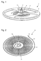
- the invention relates to a resonator 1 of the balance 3-spiral type 5.
- the balance 3 and the spiral 5 are preferably mounted on the same axis 7.
- E the Young's modulus of the material used, h its height, e its thickness and L its developed length.
- the thermal dependence also includes a possible contribution of the maintenance system such as, for example, a Swiss lever escapement (not shown) cooperating with the ankle 9 of the plate 11 also mounted on the axis 7.
- a Swiss lever escapement (not shown) cooperating with the ankle 9 of the plate 11 also mounted on the axis 7.
- the invention more particularly relates to a resonator 1 in which the hairspring 5 is used to thermally compensate the whole of the resonator 1, that is to say all the parts and in particular the balance 3.
- a hairspring 5 is generally called a compensating spiral. Therefore, the invention relates to a manufacturing method for ensuring a very high dimensional accuracy of the spiral and, incidentally, to ensure a more precise stiffness of said spiral.
- the compensating spiral 5, 15 is formed based on a material, optionally coated with a thermal compensation layer, and intended to cooperate with a predetermined balance beam 3 of inertia.
- a material optionally coated with a thermal compensation layer, and intended to cooperate with a predetermined balance beam 3 of inertia.
- the silicon-based material used for producing the compensating balance spring may be monocrystalline silicon regardless of its crystalline orientation, doped monocrystalline silicon regardless of its crystalline orientation, amorphous silicon, porous silicon or polycrystalline silicon, silicon nitride, silicon carbide, quartz whatever its crystalline orientation or silicon oxide.
- silicon-based material may be monocrystalline silicon regardless of its crystalline orientation, doped monocrystalline silicon regardless of its crystalline orientation, amorphous silicon, porous silicon or polycrystalline silicon, silicon nitride, silicon carbide, quartz whatever its crystalline orientation or silicon oxide.
- other materials can be envisioned as a glass, a ceramic, a cermet, a metal or a metal alloy.
- the explanation below will be focused on a silicon-based material.
- Each type of material may be surface-modified or layer-coated to thermally compensate for the base material as explained above.
- etching spirals in a silicon-based wafer, by means of a deep reactive ion etching (also known by the abbreviation "DRIE"), is the most accurate, phenomena that occur during the engraving or between two successive engravings can nevertheless induce geometric variations.
- DRIE deep reactive ion etching
- FIB localized ion etching
- galvanic growth growth by chemical vapor deposition or chemical engraving, which are less accurate and for which the process would make even more sense.
- the invention relates to a method 31 for manufacturing a spiral 5c.
- the method 31 comprises, as illustrated in FIG. figure 7 a first step 33 intended to form at least one hairspring 5a, for example based on silicon, according to dimensions Da less than the dimensions Db necessary to obtain said hairspring 5c of a predetermined stiffness C.
- the spiral section 5a has a height H 1 and a thickness E 1 .
- the dimensions Da of the hairspring 5a are substantially between 1% and 20% lower than those Db of the hairspring 5c necessary to obtain said hairspring 5c of a predetermined stiffness C.
- step 33 is carried out using a deep reactive ion etching in a wafer 23 of a silicon-based material as illustrated in FIG. figure 6 .
- the opposite faces F 1 , F 2 are corrugated because a deep reactive ion etching of the Bosch type causes a slot etching structured by the successive stages of attack and passivation.
- step 33 can not be limited to a particular step 33.
- step 33 could equally well be obtained by chemical etching in a wafer 23 of a material for example based on silicon.
- step 33 means that one or more spirals are formed, i.e., step 33 makes it possible to form bulk spirals or alternately formed in a wafer of a material.
- step 33 several spirals 5a may be formed in the same plate 23 in dimensions Da, H 1 , E 1 smaller than the dimensions Db, H 2 , E 2 needed to obtain several spirals 5c of a predetermined stiffness C or several spirals 5c of several predetermined stiffnesses C.
- Step 33 is also not limited to the formation of a hairspring 5a in dimensions Da, H 1 , E 1 smaller than the dimensions Db, H 2 , E 2 necessary to obtain a hairspring 5c of a predetermined stiffness C , formed using a single material.
- the step 33 could equally well form a hairspring 5a according to dimensions Da, H 1 , E 1 smaller than the dimensions Db, H 2 , E 2 needed to obtain a hairspring 5c of a predetermined stiffness C of a composite material. that is to say comprising several different materials.
- the method 31 includes a second step 35 for determining the stiffness of the hairspring 5a.
- a step 35 may be carried out directly on the hairspring 5a still attached to the wafer 23 or on the hairspring 5a previously detached from the wafer 23, on the whole, or on a sample of the spirals still attached to a wafer 23 or on a spiral sample previously detached from a wafer 23.
- the step 35 comprises a first phase intended to measure the frequency f of an assembly comprising the hairspring 5a coupled with a balance provided with an inertia I predetermined, then, using the relationship (5), deduce, in a second phase, the stiffness C spiral 5a.
- Such a measurement phase can in particular be dynamic and carried out according to the teachings of the document EP 2 423 764 , incorporated by reference into the present application.
- a static method carried out according to the teachings of the document EP 2 423 764 can also be used to determine the stiffness C of the spiral 5a.
- step 35 may also consist of a determination of the average stiffness of a representative sample or of all spirals formed on the same plate.
- the method 31 comprises a step 37 intended to calculate, using the relation (2), the thickness of the missing material for obtain the hairspring 5c of a predetermined stiffness C , that is to say the volume of material to be added and / or to modify homogeneously or not on the surface of the hairspring 5a.
- step 39 intended to modify the hairspring 5a formed during step a), to compensate for said thickness of missing material making it possible to obtain the hairspring 5c with the dimensions Db, H 2 , E 2 required for said stiffness C predetermined. It is therefore understood that it does not matter that the geometric variations have occurred on the thickness and / or the height and / or the length of the hairspring 5a insofar as, according to equation (2), it is the product h ⁇ E 3 which determines the rigidity of the turn.
- a homogeneous thickness over the entire external surface may be added and / or modified, a non-homogeneous thickness over the entire external surface may be added and / or modified, a uniform thickness only over a portion of the outer surface may be added and / or modified, or a non-homogeneous thickness only on a portion of the outer surface may be added and / or modified.
- step 39 could consist of adding material only according to the thickness E 1 or according to the height H 1 of the spiral 5a.
- step 39 comprises a phase d1 intended to deposit a layer on a portion of the outer surface of the hairspring 5a formed during step 33 in order to obtain the hairspring 5c with dimensions Db, H 2 , E 2 required for said predetermined stiffness C.
- a phase d1 can, for example, be obtained by thermal oxidation, by galvanic growth, by physical vapor deposition (known by the abbreviation “PVD”), by chemical vapor deposition (known by the abbreviation “CVD”), by atomic layer deposition (known by the abbreviation "ALD”) or by any other additive method.
- phase d1 may, for example, be carried out by a chemical vapor deposition for forming polysilicon on the hairspring 5a in monocrystalline silicon in order to obtain the hairspring 5c with dimensions Db, H 2 , E 2 necessary for the predetermined stiffness C.
- the spiral section 5c has a height H 2 and a thickness E 2 . It can be seen that the hairspring 5c is formed of a central portion 22 based on monocrystalline silicon and a peripheral portion 24 made of polycrystalline silicon according to the overall dimensions Db required for the predetermined stiffness C.
- step 39 may consist of a d2 phase to modify the structure in a predetermined depth of a portion of the outer surface 5a of the spiral to obtain the spiral 5c the dimensions Db, H 2, E 2 necessary for the predetermined stiffness C.
- amorphous silicon is used to form the hairspring 5a, it may be provided to crystallize it to a predetermined depth forming a central portion 22 of amorphous silicon and a peripheral portion 24 of polycrystalline silicon to obtain the hairspring 5c with dimensions Db , H 2 , E 2 required for the predetermined stiffness C.
- step 39 may consist of a phase d3 intended to modify the composition to a predetermined depth of a portion of the outer surface of the hairspring 5a of a predetermined stiffness C.
- a monocrystalline or polycrystalline silicon is used to form the hairspring 5a, it may be provided to dope or diffuse interstitial or substitutional atoms therein at a predetermined depth forming a central portion 22 of monocrystalline or polycrystalline silicon and a part peripheral 24 doped or diffused with the aid of atoms different from the silicon in order to obtain the spiral 5c with the dimensions Db, H 2 , E 2 necessary for the predetermined stiffness C.
- this third variant does not necessarily imply an increase in volume but at least superficially increases the Young's modulus making it possible to obtain the predetermined stiffness C.
- Step 39 may finish process 31. However, after step 39, method 31 may also perform, at least one more time, steps 35, 37 and 39 in order to further refine the dimensional quality of the hairspring .
- steps 35, 37 and 39 may, for example, be of particular interest when the execution of the first iteration of steps 35, 37 and 39 is performed on the set, or on a sample, of the spirals still attached to a wafer 23, then in a second iteration, on the assembly, or a sample, spirals previously detached from the wafer 23 having undergone the first iteration.
- the method 31 may also continue with all or part of the process 40 illustrated in FIG. figure 7 comprising optional steps 41, 43 and 45.
- the method 31 can thus continue with step 41 intended to form, on at least a part of the hairspring 5c, a portion 26 for correcting the stiffness of the spiral 5c and form a spiral 5, 15 less sensitive to thermal variations.
- step 41 may consist of a phase e1 intended to deposit a layer on a portion of the outer surface of said hairspring 5c of a predetermined stiffness C.
- the phase e1 may consist in oxidizing the spiral 5c to coat it with silicon dioxide in order to correct the stiffness of the spiral 5c and form a spiral 5, 15 which is thermally compensated.
- a phase e1 can, for example, be obtained by thermal oxidation.
- thermal oxidation can, for example, be carried out between 800 and 1200 ° C under an oxidizing atmosphere using water vapor or oxygen gas to form silicon oxide on the spiral 5c.
- the balance spring 5, 15 as shown in FIG. figure 5 which, advantageously according to the invention, comprises a composite core 22/24 based on silicon and a coating 26 based on silicon oxide.
- the balance spring 5, 15 compensator thus has a very high dimensional accuracy especially as to the height H 3 and the thickness E 3 , and, incidentally, a thermal compensation of the entire resonator 1 very thin .
- the overall dimensions Db can be found using the teachings of the document EP 1 422 436 to apply it to the resonator 1 which is intended to be manufactured, that is to say to compensate for all the constituent parts of the resonator 1 as explained above.
- step 41 may consist of a phase e2 intended to modify the structure to a predetermined depth of a portion of the outer surface of said hairspring 5c of a predetermined stiffness C.
- a phase e2 intended to modify the structure to a predetermined depth of a portion of the outer surface of said hairspring 5c of a predetermined stiffness C.
- an amorphous silicon is used for the peripheral portion 24 and, optionally, the central portion 22, it can be provided to crystallize it to a predetermined depth in the peripheral portion 24 and, optionally, in the central portion 22.
- step 41 may consist of a phase e3 intended to modify the composition to a predetermined depth of a portion of the outer surface of said hairspring 5c of a predetermined stiffness C.
- a monocrystalline or polycrystalline silicon is used for the peripheral part 24 and, possibly, the central part 22, it can be provided to dope it or to diffuse interstitial or substitutional atoms to a predetermined depth. in the peripheral portion 24 and, optionally, in the central portion 22.
- the method 31 can also comprise step 45 intended to assemble a compensating hairspring 5, 15 obtained during step 41, or a hairspring 5c obtained during step 39, with a predetermined inertia beam obtained during of step 43 to form a resonator 1 of the balance-balance type which is thermally compensated or not, that is to say whose frequency f is sensitive or not to temperature variations.
- the balance even if it comprises a predefined construction inertia, may comprise movable weights to provide a setting parameter before or after the sale of the timepiece.
- step 39 and step 41 could be provided in order to deposit a functional or aesthetic layer, such as, for example, a layer of curing or a luminescent layer.
- step 35 is not systematically implemented.
Landscapes
- Physics & Mathematics (AREA)
- General Physics & Mathematics (AREA)
- Engineering & Computer Science (AREA)
- Manufacturing & Machinery (AREA)
- Metallurgy (AREA)
- Optics & Photonics (AREA)
- Plasma & Fusion (AREA)
- Springs (AREA)
- Micromachines (AREA)
Abstract
Procédé de fabrication d'un spiral (5c) d'une raideur (C) prédéterminée comportant les étapes de fabrication a) d'un spiral (5c) selon des dimensions permettant d'obtenir une raideur (C) volontairement inférieure, de détermination de la raideur (C) du spiral (5c) formé lors de l'étape a) et de modification du spiral formé lors de l'étape a) afin de compenser ladite épaisseur de matériau manquant pour obtenir le spiral (5c) aux dimensions nécessaires à ladite raideur (C) prédéterminée.A method of manufacturing a hairspring (5c) of predetermined stiffness (C) comprising the steps of manufacturing a) a hairspring (5c) in dimensions to obtain a deliberately lower stiffness (C) the stiffness (C) of the hairspring (5c) formed during step a) and the modification of the hairspring formed during step a) in order to compensate for said thickness of missing material to obtain the hairspring (5c) of the dimensions necessary for said stiffness (C) predetermined.
Description
L'invention se rapporte à un procédé de fabrication d'un spiral d'une raideur prédéterminée et, plus précisément, un tel spiral utilisé comme spiral compensateur coopérant avec un balancier d'inertie prédéterminée pour former un résonateur comportant une fréquence prédéterminée.The invention relates to a method of manufacturing a hairspring of predetermined stiffness and, more precisely, such a hairspring used as a compensating hairspring cooperating with a predetermined inertia beam to form a resonator having a predetermined frequency.
Il est expliqué dans le document
Fabriquer un tel spiral compensateur apporte de nombreux avantages mais possède également des inconvénients. En effet, l'étape de gravage de plusieurs spiraux dans une plaquette de silicium offre une dispersion géométrique non négligeable entre les spiraux d'une même plaquette et une dispersion plus grande entre des spiraux de deux plaquettes gravées à des moments différents. Incidemment, la raideur de chaque spiral gravé avec le même motif de gravage est variable en créant des dispersions de fabrication non négligeables.Making such a compensating hairspring provides many benefits but also has disadvantages. In fact, the step of etching several spirals in a silicon wafer offers a non-negligible geometrical dispersion between the spirals of the same wafer and a greater dispersion between spirals of two wafers etched at different times. Incidentally, the stiffness of each spiral engraved with the same engraving pattern is variable by creating significant manufacturing dispersions.
Le but de la présente invention est de pallier tout ou partie les inconvénients cités précédemment en proposant un procédé de fabrication d'un spiral dont les dimensions sont suffisamment précises pour ne pas nécessiter de retouche.The object of the present invention is to overcome all or part of the disadvantages mentioned above by proposing a manufacturing process a spiral whose dimensions are precise enough not to require retouching.
A cet effet, l'invention se rapporte à un procédé de fabrication d'un spiral d'une raideur prédéterminée comportant les étapes suivantes :
- a) former un spiral selon des dimensions inférieures aux dimensions nécessaires pour obtenir ledit spiral d'une raideur prédéterminée ;
- b) déterminer la raideur du spiral formé lors de l'étape a) ;
- c) calculer l'épaisseur de matériau manquante pour obtenir ledit spiral d'une raideur prédéterminée ;
- d) modifier le spiral formé lors de l'étape a), pour compenser ladite épaisseur de matériau manquante permettant d'obtenir le spiral (5c) aux dimensions nécessaires à ladite raideur prédéterminée.
- a) forming a hairspring having dimensions smaller than the dimensions necessary to obtain said hairspring of a predetermined stiffness;
- b) determining the stiffness of the hairspring formed during step a);
- c) calculating the thickness of missing material to obtain said hairspring of a predetermined stiffness;
- d) modifying the spiral formed during step a), to compensate for said thickness of missing material to obtain the spiral (5c) to the dimensions necessary for said predetermined stiffness.
On comprend donc que le procédé permet de garantir une très haute précision dimensionnelle du spiral et, incidemment, de garantir une raideur plus précise dudit spiral. Chaque paramètre de fabrication, pouvant induire des variations géométriques lors de l'étape a), peut ainsi être totalement rectifié pour chaque spiral fabriqué ou rectifié en moyenne pour l'ensemble des spiraux formés en même temps permettant de diminuer drastiquement le taux de rebut.It is therefore clear that the method makes it possible to guarantee a very high dimensional accuracy of the hairspring and, incidentally, to guarantee a more precise stiffness of said hairspring. Each manufacturing parameter, which can induce geometric variations during step a), can be completely rectified for each spiral manufactured or rectified on average for all the spirals formed at the same time to drastically reduce the scrap rate.
Conformément à d'autres variantes avantageuses de l'invention :
- lors de l'étape a), les dimensions du spiral formé lors de l'étape a) sont entre 1% et 20% inférieures à celles nécessaires pour obtenir ledit spiral à ladite raideur prédéterminée ;
- l'étape a) est réalisée à l'aide d'un gravage ionique réactif profond ou d'un gravage chimique ;
- lors de l'étape a), plusieurs spiraux sont formés dans une même plaquette selon des dimensions inférieures aux dimensions nécessaires pour obtenir plusieurs spiraux d'une raideur prédéterminée ou plusieurs spiraux de plusieurs raideurs prédéterminées ;
- le spiral formé lors de l'étape a) est à base de silicium, de verre, de céramique, de métal ou d'alliage métallique ;
- l'étape b) comporte les phases b1) : mesurer la fréquence d'un ensemble comportant le spiral formé lors de l'étape a) couplé avec un balancier doté d'une inertie prédéterminée et b2) : déduire de la fréquence mesurée, la raideur du spiral formé lors de l'étape a) ;
- selon une première variante, l'étape d) comporte la phase d1) : déposer une couche sur une partie de la surface externe du spiral formé lors de l'étape a) afin d'obtenir le spiral aux dimensions nécessaires à ladite raideur prédéterminée ;
- selon une deuxième variante, l'étape d) comporte la phase d2) : modifier la structure selon une profondeur prédéterminée d'une partie de la surface externe du spiral formé lors de l'étape a) afin d'obtenir le spiral aux dimensions nécessaires à ladite raideur prédéterminée ;
- selon une troisième variante, l'étape d) comporte la phase d3) : modifier la composition selon une profondeur prédéterminée d'une partie de la surface externe du spiral obtenu lors de l'étape a) afin d'obtenir le spiral aux dimensions nécessaires à ladite raideur prédéterminée ;
- après l'étape d), le procédé effectue au moins une nouvelle fois les étapes b), c) et d) pour affiner la qualité dimensionnelle ;
- selon une première variante, l'étape e) comporte la phase e1) : déposer une couche sur une partie de la surface externe dudit spiral d'une raideur prédéterminée ;
- selon une deuxième variante, l'étape e) comporte la phase e2) : modifier la structure selon une profondeur prédéterminée d'une partie de la surface externe dudit spiral d'une raideur prédéterminée ;
- selon une troisième variante, l'étape e) comporte la phase e3) : modifier la composition selon une profondeur prédéterminée d'une partie de la surface externe dudit spiral d'une raideur prédéterminée.
- during step a), the dimensions of the hairspring formed during step a) are between 1% and 20% lower than those necessary to obtain said hairspring at said predetermined stiffness;
- step a) is carried out using deep reactive ion etching or chemical etching;
- during step a), a plurality of spirals are formed in the same plate in dimensions smaller than the dimensions necessary to obtain several spirals of a predetermined stiffness or several spirals of several predetermined stiffnesses;
- the spiral formed during step a) is based on silicon, glass, ceramic, metal or metal alloy;
- step b) comprises the phases b1): measuring the frequency of an assembly comprising the hairspring formed during step a) coupled with a balance having a predetermined inertia and b2): deducing from the measured frequency, the stiffness of the spiral formed during step a);
- according to a first variant, step d) comprises the phase d1): depositing a layer on a portion of the outer surface of the spiral formed during step a) in order to obtain the spiral to the dimensions necessary for said predetermined stiffness;
- according to a second variant, step d) comprises phase d2): modifying the structure to a predetermined depth of a portion of the outer surface of the hairspring formed during step a) in order to obtain the hairspring of necessary dimensions at said predetermined stiffness;
- according to a third variant, step d) comprises phase d3): modifying the composition to a predetermined depth of a portion of the outer surface of the hairspring obtained during step a) in order to obtain the hairspring with the necessary dimensions at said predetermined stiffness;
- after step d), the method performs at least one more step b), c) and d) to refine the dimensional quality;
- according to a first variant, step e) comprises the phase e1): depositing a layer on a portion of the outer surface of said hairspring of a predetermined stiffness;
- according to a second variant, the step e) comprises the phase e2): modifying the structure according to a predetermined depth of a part of the external surface of said hairspring with a predetermined stiffness;
- according to a third variant, step e) comprises phase e3): modifying the composition to a predetermined depth of a portion of the outer surface of said hairspring of a predetermined stiffness.
D'autres particularités et avantages ressortiront clairement de la description qui en est faite ci-après, à titre indicatif et nullement limitatif, en référence aux dessins annexés, dans lesquels :
- la
figure 1 est une vue en perspective d'un résonateur assemblé selon l'invention ; - la
figure 2 est un exemple de géométrie de spiral selon l'invention ; - les
figures 3 à 5 sont des sections de spiral à différentes étapes du procédé selon l'invention ; - la
figure 6 est une représentation en perspective d'une étape du procédé selon l'invention ; - la
figure 7 est un diagramme du procédé selon l'invention.
- the
figure 1 is a perspective view of an assembled resonator according to the invention; - the
figure 2 is an example of spiral geometry according to the invention; - the
Figures 3 to 5 are spiral sections at different stages of the process according to the invention; - the
figure 6 is a perspective representation of a step of the method according to the invention; - the
figure 7 is a diagram of the process according to the invention.
Comme illustré à la ![]()
![]()
De plus, la raideur C du spiral 5 à section constante répond à la formule : ![]()
![]()
De plus, la raideur C d'un spiral 5 à section variable répond à la formule : 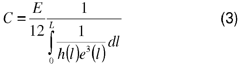
De plus, la raideur C d'un spiral 5 à épaisseur variable mais à hauteur constante répond à la formule : 
Enfin, la fréquence f du résonateur 1 balancier-spiral répond à la formule : ![]()
![]()
Selon l'invention, il est souhaité que la variation de la fréquence en fonction de la température d'un résonateur soit sensiblement nulle. La variation de la fréquence f en fonction de la température T dans le cas d'un résonateur balancier-spiral suit sensiblement la formule suivante : ![]()
-

- ΔT est la variation de la température ;
-

- α s est le coefficient de dilatation du spiral, exprimé en ppm. °C-1 ;
- αb est le coefficient de dilatation du balancier, exprimé en ppm. °C-1 ;
-
- ΔT is the variation of the temperature;
-
- α s is the spiral expansion coefficient, expressed in ppm. ° C -1 ;
- α b is the coefficient of expansion of the balance, expressed in ppm. ° C -1 ;
Les oscillations de tout résonateur destiné à une base de temps ou de fréquence devant être entretenues, la dépendance thermique comprend également une contribution éventuelle du système d'entretien comme, par exemple, un échappement à ancre suisse (non représenté) coopérant avec la cheville 9 du plateau 11 également monté sur l'axe 7.Oscillations of any resonator for a time base or frequency to be maintained, the thermal dependence also includes a possible contribution of the maintenance system such as, for example, a Swiss lever escapement (not shown) cooperating with the ankle 9 of the
On comprend donc, à partir des formules (1)-(6), qu'il est possible par le choix des matériaux utilisés de coupler le spiral 5 avec le balancier 3 afin que la fréquence f du résonateur 1 soit quasiment insensible aux variations de température.It is therefore understood from the formulas (1) - (6) that it is possible by the choice of materials used to couple the
L'invention concerne plus particulièrement un résonateur 1 dans lequel le spiral 5 est utilisé pour compenser thermiquement l'ensemble du résonateur 1, c'est-à-dire toutes les parties et notamment le balancier 3. Un tel spiral 5 est généralement appelé un spiral compensateur. C'est pourquoi, l'invention se rapporte à un procédé de fabrication permettant de garantir une très haute précision dimensionnelle du spiral et, incidemment, de garantir une raideur plus précise dudit spiral.The invention more particularly relates to a
Selon l'invention, le spiral compensateur 5, 15 est formé à base d'un matériau, éventuellement revêtu d'une couche de compensation thermique, et destiné à coopérer avec un balancier 3 d'inertie prédéterminée. Toutefois, rien n'empêche de prévoir un balancier avec des masselottes déplaçables permettant d'offrir un paramètre de réglage avant ou après la vente de la pièce d'horlogerie.According to the invention, the compensating
L'utilisation d'un matériau, par exemple à base de silicium, de verre ou de céramique, pour la fabrication d'un spiral 5, 15 offre l'avantage d'être précis par les méthodes de gravage existantes et de posséder de bonnes propriétés mécaniques et chimiques en étant notamment très peu sensible aux champs magnétiques. Il doit en revanche être revêtu ou modifié superficiellement pour pouvoir former un spiral compensateur.The use of a material, for example based on silicon, glass or ceramic, for the manufacture of a
Préférentiellement, le matériau à base de silicium utilisé pour la réalisation du spiral compensateur peut être du silicium monocristallin quelle que soit son orientation cristalline, du silicium monocristallin dopé quelle que soit son orientation cristalline, du silicium amorphe, du silicium poreux, du silicium polycristallin, du nitrure de silicium, du carbure de silicium, du quartz quelle que soit son orientation cristalline ou de l'oxyde de silicium. Bien entendu d'autres matériaux peuvent être envisagés comme un verre, une céramique, un cermet, un métal ou un alliage métallique. Par simplification, l'explication ci-dessous sera portée sur un matériau à base de silicium.Preferably, the silicon-based material used for producing the compensating balance spring may be monocrystalline silicon regardless of its crystalline orientation, doped monocrystalline silicon regardless of its crystalline orientation, amorphous silicon, porous silicon or polycrystalline silicon, silicon nitride, silicon carbide, quartz whatever its crystalline orientation or silicon oxide. Of course other materials can be envisioned as a glass, a ceramic, a cermet, a metal or a metal alloy. For simplicity, the explanation below will be focused on a silicon-based material.
Chaque type de matériau peut être modifié superficiellement ou revêtu d'une couche afin de compenser thermiquement le matériau de base comme expliqué ci-dessus.Each type of material may be surface-modified or layer-coated to thermally compensate for the base material as explained above.
Si l'étape de gravage de spiraux dans une plaquette à base de silicium, au moyen d'un gravage ionique réactif profond (également connu sous l'abréviation « D.R.I.E. »), est la plus précise, des phénomènes qui interviennent lors du gravage ou entre deux gravages successifs peuvent néanmoins induire des variations géométriques.If the step of etching spirals in a silicon-based wafer, by means of a deep reactive ion etching (also known by the abbreviation "DRIE"), is the most accurate, phenomena that occur during the engraving or between two successive engravings can nevertheless induce geometric variations.
Bien entendu, d'autres types de fabrication peuvent être mis en oeuvre, comme le gravage laser, le gravage ionique localisé (connu sous l'abréviation anglaise « F.I.B. »), la croissance galvanique, la croissance par dépôt chimique en phase gazeuse ou le gravage chimique, qui sont moins précis et pour lesquels le procédé aurait encore plus de sens.Of course, other types of manufacturing can be implemented, such as laser etching, localized ion etching (known by the abbreviation "FIB"), galvanic growth, growth by chemical vapor deposition or chemical engraving, which are less accurate and for which the process would make even more sense.
Ainsi, l'invention se rapporte à un procédé 31 de fabrication d'un spiral 5c. Selon l'invention, le procédé 31 comporte, comme illustré à la
Préférentiellement, les dimensions Da du spiral 5a sont sensiblement entre 1% et 20% inférieures à celles Db du spiral 5c nécessaires pour obtenir ledit spiral 5c d'une raideur C prédéterminée.Preferably, the dimensions Da of the
Préférentiellement selon l'invention, l'étape 33 est réalisée à l'aide d'un gravage ionique réactif profond dans une plaquette 23 d'un matériau à base de silicium comme illustré à la
Bien entendu, le procédé ne saurait se limiter à une étape 33 particulière. A titre d'exemple, l'étape 33 pourrait tout aussi bien être obtenue par un gravage chimique dans une plaquette 23 d'un matériau par exemple à base de silicium. De plus, l'étape 33 signifie que un ou plusieurs spiraux sont formés, c'est-à-dire que l'étape 33 permet de former des spiraux en vrac ou alternativement formés dans une plaquette d'un matériau.Of course, the method can not be limited to a
Par conséquent, lors de l'étape 33, plusieurs spiraux 5a peuvent être formés dans la même plaquette 23 selon des dimensions Da, H1, E1 inférieures aux dimensions Db, H2, E2 nécessaires pour obtenir plusieurs spiraux 5c d'une raideur C prédéterminée ou plusieurs spiraux 5c de plusieurs raideurs C prédéterminées.Therefore, in
L'étape 33 ne se limite pas non plus à la formation d'un spiral 5a selon des dimensions Da, H1, E1 inférieures aux dimensions Db, H2, E2 nécessaires pour obtenir un spiral 5c d'une raideur C prédéterminée, formé à l'aide d'un unique matériau. Ainsi, l'étape 33 pourrait tout aussi bien former un spiral 5a selon des dimensions Da, H1, E1 inférieures aux dimensions Db, H2, E2 nécessaires pour obtenir un spiral 5c d'une raideur C prédéterminée en un matériau composite, c'est-à-dire comportant plusieurs matériaux distincts.
Le procédé 31 comporte une deuxième étape 35 destinée à déterminer la raideur du spiral 5a. Une telle étape 35 peut être réalisée directement sur le spiral 5a encore attaché à la plaquette 23 ou sur le spiral 5a préalablement détaché de la plaquette 23, sur l'ensemble, ou sur un échantillon des spiraux encore attachés à une plaquette 23 ou sur un échantillon de spiraux préalablement détachés d'une plaquette 23.The
Préférentiellement selon l'invention, le spiral 5a étant ou non détaché de la plaquette 23, l'étape 35 comporte une première phase destinée à mesurer la fréquence f d'un ensemble comportant le spiral 5a couplé avec un balancier doté d'une inertie I prédéterminée puis, à l'aide de la relation (5), en déduire, dans une deuxième phase, la raideur C du spiral 5a.Preferably according to the invention, the
Une telle phase de mesure peut notamment être dynamique et réalisée selon les enseignements du document
Bien entendu, comme expliqué ci-dessus, le procédé ne se limitant pas au gravage d'un unique spiral par plaquette, l'étape 35 peut également consister en une détermination de la raideur moyenne d'un échantillon représentatif ou de l'ensemble des spiraux formés sur une même plaquette.Of course, as explained above, the method is not limited to the etching of a single spiral per wafer, step 35 may also consist of a determination of the average stiffness of a representative sample or of all spirals formed on the same plate.
Avantageusement selon l'invention, à partir de la détermination de la raideur C du spiral 5a, le procédé 31 comporte une étape 37 destinée à calculer, à l'aide de la relation (2), l'épaisseur de matériau manquante pour obtenir le spiral 5c d'une raideur C prédéterminée, c'est-à-dire le volume de matériau à ajouter et/ou à modifier de manière homogène ou non sur la surface du spiral 5a.Advantageously according to the invention, from the determination of the stiffness C of the
Le procédé se poursuit avec une étape 39 destinée à modifier le spiral 5a formé lors de l'étape a), pour compenser ladite épaisseur de matériau manquante permettant d'obtenir le spiral 5c aux dimensions Db, H2, E2 nécessaires à ladite raideur C prédéterminée. On comprend donc qu'il importe peu que les variations géométriques soient intervenues sur l'épaisseur et/ou la hauteur et/ou la longueur du spiral 5a dans la mesure où, selon l'équation (2), c'est le produit h·e3 qui détermine la rigidité de la spire.The method is continued with a
Ainsi, une épaisseur homogène sur toute la surface externe peut être ajoutée et/ou modifiée, une épaisseur non homogène sur toute la surface externe peut être ajoutée et/ou modifiée, une épaisseur homogène seulement sur une partie de la surface externe peut être ajoutée et/ou modifiée, ou une épaisseur non homogène seulement sur une partie de la surface externe peut être ajoutée et/ou modifiée. A titre d'exemple, l'étape 39 pourrait consister à ne rajouter de la matière que selon l'épaisseur E1 ou selon la hauteur H1 du spiral 5a.Thus, a homogeneous thickness over the entire external surface may be added and / or modified, a non-homogeneous thickness over the entire external surface may be added and / or modified, a uniform thickness only over a portion of the outer surface may be added and / or modified, or a non-homogeneous thickness only on a portion of the outer surface may be added and / or modified. By way of example, step 39 could consist of adding material only according to the thickness E 1 or according to the height H 1 of the
Dans une première variante, l'étape 39 comporte une phase d1 destinée à déposer une couche sur une partie de la surface externe du spiral 5a formé lors de l'étape 33 afin d'obtenir le spiral 5c aux dimensions Db, H2, E2 nécessaires à ladite raideur C prédéterminée. Une telle phase d1 peut, par exemple, être obtenue par oxydation thermique, par croissance galvanique, par dépôt physique en phase vapeur (connu sous l'abréviation anglaise « P.V.D. »), par dépôt chimique en phase vapeur (connu sous l'abréviation anglaise « C.V.D. »), par dépôt en couche atomique (connu sous l'abréviation anglaise « A.L.D. ») ou par toute autre méthode additive.In a first variant,
Une telle phase d1 peut, par exemple, être réalisée par un dépôt chimique en phase vapeur permettant de former du polysilicium sur le spiral 5a en silicium monocristallin afin d'obtenir le spiral 5c aux dimensions Db, H2, E2 nécessaires à la raideur C prédéterminée.Such a phase d1 may, for example, be carried out by a chemical vapor deposition for forming polysilicon on the
Comme visible à la
Dans une deuxième variante, l'étape 39 peut consister en une phase d2 destinée à modifier la structure selon une profondeur prédéterminée d'une partie de la surface externe du spiral 5a afin d'obtenir le spiral 5c aux dimensions Db, H2, E2 nécessaires à la raideur C prédéterminée. A titre d'exemple illustré à la
Dans une troisième variante, l'étape 39 peut consister en une phase d3 destinée à modifier la composition selon une profondeur prédéterminée d'une partie de la surface externe du spiral 5a d'une raideur C prédéterminée. A titre d'exemple illustré à la
Pour ces trois variantes, il est visible que la forme en créneaux est toujours reproduite sur une portion de la partie périphérique 24 et la partie centrale 22. Ainsi, une étape de lissage avant l'étape 39 peut être prévue pour atténuer, voire enlever, l'éventuelle forme en créneaux du spiral 5a.For these three variants, it is visible that the crenellated form is always reproduced on a portion of the
L'étape 39 peut finir le procédé 31. Toutefois, après l'étape 39, le procédé 31 peut également effectuer, au moins une nouvelle fois, les étapes 35, 37 et 39 dans le but d'encore affiner la qualité dimensionnelle du spiral. Ces itérations des étapes 35, 37 et 39 peuvent, par exemple, trouver un intérêt particulier quand l'exécution de la première itération des étapes 35, 37 et 39 est réalisée sur l'ensemble, ou sur un échantillon, des spiraux encore attachés à une plaquette 23, puis dans une deuxième itération, sur l'ensemble, ou un échantillon, des spiraux préalablement détachés de la plaquette 23 ayant subi la première itération.
Le procédé 31 peut également se poursuivre avec tout ou partie du processus 40 illustré à la
Dans une première variante, l'étape 41 peut consister en une phase e1 destinée à déposer une couche sur une partie de la surface externe dudit spiral 5c d'une raideur C prédéterminée.In a first variant, step 41 may consist of a phase e1 intended to deposit a layer on a portion of the outer surface of said
Dans le cas où les parties 22/24 sont un matériau à base de silicium, la phase e1 peut consister à oxyder le spiral 5c pour le revêtir de dioxyde de silicium afin de corriger la raideur du spiral 5c et de former un spiral 5, 15 qui est thermocompensé. Une telle phase e1 peut, par exemple, être obtenue par oxydation thermique. Une telle oxydation thermique peut, par exemple, être réalisée entre 800 et 1200 °C sous atmosphère oxydante à l'aide de vapeur d'eau ou de gaz de dioxygène permettant de former de l'oxyde de silicium sur le spiral 5c.In the case where the
On obtient ainsi le spiral 5, 15 compensateur comme illustré à la
Dans le cas d'un spiral à base de silicium, les dimensions globales Db peuvent être trouvées en utilisant les enseignements du document
Dans une deuxième variante, l'étape 41 peut consister en une phase e2 destinée à modifier la structure selon une profondeur prédéterminée d'une partie de la surface externe dudit spiral 5c d'une raideur C prédéterminée. A titre d'exemple, si un silicium amorphe est utilisé pour la partie périphérique 24 et, éventuellement, la partie centrale 22, il peut être prévu de le cristalliser selon une profondeur prédéterminée dans la partie périphérique 24 et, éventuellement, dans la partie centrale 22.In a second variant, step 41 may consist of a phase e2 intended to modify the structure to a predetermined depth of a portion of the outer surface of said
Dans une troisième variante, l'étape 41 peut consister en une phase e3 destinée à modifier la composition selon une profondeur prédéterminée d'une partie de la surface externe dudit spiral 5c d'une raideur C prédéterminée. A titre d'exemple, si un silicium monocristallin ou polycristallin est utilisé pour la partie périphérique 24 et, éventuellement, la partie centrale 22, il peut être prévu de le doper ou d'y diffuser des atomes interstitiels ou de substitution selon une profondeur prédéterminée dans la partie périphérique 24 et, éventuellement, dans la partie centrale 22.In a third variant, step 41 may consist of a phase e3 intended to modify the composition to a predetermined depth of a portion of the outer surface of said
Avantageusement selon l'invention, il est ainsi possible de fabriquer, comme illustré à la
- une ou plusieurs spires de section(s) plus précise(s) que celle obtenue par un unique gravage ;
- des variations d'épaisseur et/ou de pas le long de la spire ;
une virole 17 monobloc ;une spire interne 19 du type à courbe Grossmann ;une attache 14 de pitonnage monobloc ;- un élément d'encastrement externe monobloc ;
une portion 13 de laspire externe 12 surépaissie et/ou de laspire interne 19 par rapport au reste des spires.
- one or more turns of more precise section (s) than that obtained by a single engraving;
- variations in thickness and / or pitch along the turn;
- a
shell 17 monobloc; - an
internal turn 19 of the Grossmann curve type; - a one-
piece pegging fastener 14; - a one-piece external recess element;
- a
portion 13 of theouter turn 12 thickened and / or theinner coil 19 relative to the rest of the turns.
Enfin, le procédé 31 peut également comporter l'étape 45 destinée à assembler un spiral compensateur 5, 15 obtenu lors de l'étape 41, ou un spiral 5c obtenu lors de l'étape 39, avec un balancier d'inertie prédéterminée obtenu lors de l'étape 43 pour former un résonateur 1 du type balancier - spiral qui est compensé thermiquement ou non, c'est-à-dire dont la fréquence f est sensible ou non aux variations de température.Finally, the
Bien entendu, la présente invention ne se limite pas à l'exemple illustré mais est susceptible de diverses variantes et modifications qui apparaîtront à l'homme de l'art. En particulier, comme expliqué ci-dessus, le balancier, même s'il comporte une inertie prédéfinie de construction, peut comporter des masselottes déplaçables permettant d'offrir un paramètre de réglage avant ou après la vente de la pièce d'horlogerie.Of course, the present invention is not limited to the illustrated example but is susceptible of various variations and modifications that will occur to those skilled in the art. In particular, as explained above, the balance, even if it comprises a predefined construction inertia, may comprise movable weights to provide a setting parameter before or after the sale of the timepiece.
De plus, une étape supplémentaire, entre l'étape 39 et l'étape 41, ou entre l'étape 39 et l'étape 45, pourrait être prévue afin de déposer une couche fonctionnelle ou esthétique, comme, par exemple, une couche de durcissement ou une couche luminescente.In addition, an additional step, between
Il est également envisageable dans le cas où le procédé 31 effectue, après l'étape 39, une ou plusieurs itération(s) des étapes 35, 37 et 39 que l'étape 35 ne soit pas systématiquement mise en oeuvre.It is also conceivable in the case where the
Claims (19)
Priority Applications (4)
| Application Number | Priority Date | Filing Date | Title |
|---|---|---|---|
| EP15201337.1A EP3181939B1 (en) | 2015-12-18 | 2015-12-18 | Method for manufacturing a hairspring with predetermined stiffness by adding material |
| JP2016234771A JP6343652B2 (en) | 2015-12-18 | 2016-12-02 | Method of manufacturing a hairspring having a predetermined thickness by adding material |
| US15/372,725 US10324418B2 (en) | 2015-12-18 | 2016-12-08 | Method for fabrication of a balance spring of predetermined thickness through the addition of material |
| CN201611164474.5A CN106997170B (en) | 2015-12-18 | 2016-12-16 | Method for manufacturing the balance spring of predetermined thickness by increasing material |
Applications Claiming Priority (1)
| Application Number | Priority Date | Filing Date | Title |
|---|---|---|---|
| EP15201337.1A EP3181939B1 (en) | 2015-12-18 | 2015-12-18 | Method for manufacturing a hairspring with predetermined stiffness by adding material |
Publications (2)
| Publication Number | Publication Date |
|---|---|
| EP3181939A1 true EP3181939A1 (en) | 2017-06-21 |
| EP3181939B1 EP3181939B1 (en) | 2019-02-20 |
Family
ID=54850481
Family Applications (1)
| Application Number | Title | Priority Date | Filing Date |
|---|---|---|---|
| EP15201337.1A Active EP3181939B1 (en) | 2015-12-18 | 2015-12-18 | Method for manufacturing a hairspring with predetermined stiffness by adding material |
Country Status (4)
| Country | Link |
|---|---|
| US (1) | US10324418B2 (en) |
| EP (1) | EP3181939B1 (en) |
| JP (1) | JP6343652B2 (en) |
| CN (1) | CN106997170B (en) |
Cited By (10)
| Publication number | Priority date | Publication date | Assignee | Title |
|---|---|---|---|---|
| WO2019166922A1 (en) | 2018-03-01 | 2019-09-06 | Csem Centre Suisse D'electronique Et De Microtechnique Sa - Recherche Et Developpement | Method for manufacturing a hairspring |
| WO2019180558A1 (en) | 2018-03-20 | 2019-09-26 | Patek Philippe Sa Geneve | Method for manufacturing thermally-compensated horology hairsprings of precise stiffness |
| EP3608727A1 (en) * | 2018-08-09 | 2020-02-12 | Nivarox-FAR S.A. | Component, in particular for a timepiece, with a surface topology and manufacturing method thereof |
| WO2021053501A1 (en) | 2019-09-16 | 2021-03-25 | Richemont International Sa | Method for manufacturing a plurality of resonators in a wafer |
| EP3982205A1 (en) | 2020-10-06 | 2022-04-13 | Patek Philippe SA Genève | Method for manufacturing a timepiece spring with precise stiffness |
| EP4030242A1 (en) | 2021-01-18 | 2022-07-20 | Richemont International S.A. | Method for manufacturing timepiece hairsprings |
| EP4030243A1 (en) | 2021-01-18 | 2022-07-20 | Richemont International S.A. | Method for monitoring and manufacturing timepiece hairsprings |
| EP4202576A1 (en) | 2021-12-22 | 2023-06-28 | Richemont International S.A. | Method for monitoring and manufacturing timepiece hairsprings |
| WO2023117350A1 (en) | 2021-12-22 | 2023-06-29 | Richemont International Sa | Method for testing and producing balance springs for timepieces |
| EP4310598A1 (en) | 2022-07-18 | 2024-01-24 | Richemont International S.A. | Method for monitoring and manufacturing timepiece hairsprings |
Families Citing this family (2)
| Publication number | Priority date | Publication date | Assignee | Title |
|---|---|---|---|---|
| EP3534222A1 (en) * | 2018-03-01 | 2019-09-04 | Rolex Sa | Method for producing a thermally compensated oscillator |
| US10703625B1 (en) * | 2019-03-29 | 2020-07-07 | Industrial Technology Research Institute | Microelectromechanical system (MEMS) apparatus with adjustable spring |
Citations (6)
| Publication number | Priority date | Publication date | Assignee | Title |
|---|---|---|---|---|
| EP1213628A1 (en) * | 2000-12-07 | 2002-06-12 | Eta SA Fabriques d'Ebauches | Method for adjusting the oscillation frequence of a sprung balance for a mechanical timepiece |
| EP1422436A1 (en) | 2002-11-25 | 2004-05-26 | CSEM Centre Suisse d'Electronique et de Microtechnique SA | Spiral watch spring and its method of production |
| WO2012007460A1 (en) * | 2010-07-16 | 2012-01-19 | Eta Sa Manufacture Horlogère Suisse | Method for adjusting the oscillation frequency, the inertia or the balance of a mobile component in a movement or in a balance and spring assembly of a timepiece |
| EP2423764A1 (en) | 2010-08-31 | 2012-02-29 | Rolex S.A. | Device for measuring the torque of a hairspring |
| EP2455825A1 (en) * | 2010-11-18 | 2012-05-23 | Nivarox-FAR S.A. | Method for matching and adjusting a timepiece subassembly |
| CH709516A2 (en) * | 2014-03-31 | 2015-10-15 | Breitling Montres Sa | Manufacturing method and adjustment method of a spiral spring by means of a laser. |
Family Cites Families (26)
| Publication number | Priority date | Publication date | Assignee | Title |
|---|---|---|---|---|
| CH483050A (en) | 1966-09-15 | 1969-08-29 | Straumann Inst Ag | Device for the electrical measurement of the moment of force of cut spiral springs and the moment of inertia of unrest |
| CH1060869A4 (en) | 1969-07-11 | 1971-06-30 | ||
| EP1445670A1 (en) | 2003-02-06 | 2004-08-11 | ETA SA Manufacture Horlogère Suisse | Balance-spring resonator spiral and its method of fabrication |
| US7102467B2 (en) | 2004-04-28 | 2006-09-05 | Robert Bosch Gmbh | Method for adjusting the frequency of a MEMS resonator |
| JP2008544290A (en) | 2005-06-28 | 2008-12-04 | ウーテーアー・エス・アー・マニファクチュール・オロロジェール・スイス | Enhanced micromechanical parts |
| EP1791039A1 (en) | 2005-11-25 | 2007-05-30 | The Swatch Group Research and Development Ltd. | Hairspring made from athermic glass for a timepiece movement and its method of manufacture |
| CH702708B1 (en) | 2007-04-27 | 2011-08-31 | Sigatec S A | Balance-hairspring oscillator assembly for mechanical watch, has balance or hairspring comprising detachable element realized during fabrication of balance or hairspring, where hairspring comprises collet connected to detachable element |
| US8414185B2 (en) | 2007-11-28 | 2013-04-09 | Manufacture Et Fabrique De Montres Et Chronometres Ulysse Nardin Le Locle S.A. | Mechanical oscillator having an optimized thermoelastic coefficient |
| CH699780B1 (en) | 2008-10-22 | 2014-02-14 | Richemont Int Sa | of self-compensating balance spring watch. |
| EP2337221A1 (en) | 2009-12-15 | 2011-06-22 | The Swatch Group Research and Development Ltd. | Resonator thermocompensated at least to the first and second orders |
| EP2561409B1 (en) | 2010-04-21 | 2019-08-28 | Team Smartfish GmbH | Element of regulation for a timepiece and a corresponding process |
| EP2590325A1 (en) | 2011-11-04 | 2013-05-08 | The Swatch Group Research and Development Ltd. | Thermally compensated ceramic resonator |
| EP2597536A1 (en) | 2011-11-25 | 2013-05-29 | CSEM Centre Suisse d'Electronique et de Microtechnique SA - Recherche et Développement | Improved spiral spring and method for manufacturing said spiral spring |
| EP2607974A1 (en) | 2011-12-22 | 2013-06-26 | The Swatch Group Research and Development Ltd. | Method for manufacturing a resonator |
| CH705945B1 (en) | 2011-12-22 | 2024-08-30 | Swatch Group Res & Dev Ltd | Method of producing a resonator and resonator obtained by such a method |
| JP2013197856A (en) | 2012-03-19 | 2013-09-30 | Seiko Instruments Inc | Piezoelectric vibration piece, piezoelectric vibrator, oscillator, electronic apparatus, and wave clock |
| EP2717103B1 (en) * | 2012-10-04 | 2017-01-11 | The Swatch Group Research and Development Ltd. | Luminour hairspring |
| EP2765705B1 (en) * | 2013-02-07 | 2015-08-19 | The Swatch Group Research and Development Ltd. | Resonator thermocompensated by a shape-memory metal |
| DE102013104248B3 (en) | 2013-04-26 | 2014-03-27 | Damasko Gmbh | Method for manufacturing spiral spring for mechanical clock movements of mechanical clock, involves providing spiral spring with spring axis, where spiral spring has average height in direction parallel to its spring axis |
| WO2014203086A1 (en) | 2013-06-21 | 2014-12-24 | Damasko Uhrenmanufaktur KG | Oscillating system for mechanical clockwork mechanisms, spiral spring and method for production thereof |
| CN106104393A (en) | 2014-01-29 | 2016-11-09 | 卡地亚国际股份公司 | The hairspring of the thermal compensation being made up of the pottery comprising silicon at it in forming and for the method regulating hairspring |
| JP6486697B2 (en) | 2014-02-26 | 2019-03-20 | シチズン時計株式会社 | Hairspring manufacturing method and hairspring |
| WO2015132259A2 (en) * | 2014-03-03 | 2015-09-11 | Richemont International Sa | Method for pairing a balance wheel and a hairspring in a regulating member |
| HK1209578A2 (en) * | 2015-02-17 | 2016-04-01 | Master Dynamic Ltd | Silicon hairspring |
| EP3106929A1 (en) * | 2015-06-16 | 2016-12-21 | Nivarox-FAR S.A. | Part with improved welding surface |
| CH709628B1 (en) | 2015-08-27 | 2016-06-15 | Csem Centre Suisse D'electronique Et De Microtechnique S A - Rech Et Développement | thermocompensated spiral spring for a timepiece movement. |
-
2015
- 2015-12-18 EP EP15201337.1A patent/EP3181939B1/en active Active
-
2016
- 2016-12-02 JP JP2016234771A patent/JP6343652B2/en active Active
- 2016-12-08 US US15/372,725 patent/US10324418B2/en active Active
- 2016-12-16 CN CN201611164474.5A patent/CN106997170B/en active Active
Patent Citations (6)
| Publication number | Priority date | Publication date | Assignee | Title |
|---|---|---|---|---|
| EP1213628A1 (en) * | 2000-12-07 | 2002-06-12 | Eta SA Fabriques d'Ebauches | Method for adjusting the oscillation frequence of a sprung balance for a mechanical timepiece |
| EP1422436A1 (en) | 2002-11-25 | 2004-05-26 | CSEM Centre Suisse d'Electronique et de Microtechnique SA | Spiral watch spring and its method of production |
| WO2012007460A1 (en) * | 2010-07-16 | 2012-01-19 | Eta Sa Manufacture Horlogère Suisse | Method for adjusting the oscillation frequency, the inertia or the balance of a mobile component in a movement or in a balance and spring assembly of a timepiece |
| EP2423764A1 (en) | 2010-08-31 | 2012-02-29 | Rolex S.A. | Device for measuring the torque of a hairspring |
| EP2455825A1 (en) * | 2010-11-18 | 2012-05-23 | Nivarox-FAR S.A. | Method for matching and adjusting a timepiece subassembly |
| CH709516A2 (en) * | 2014-03-31 | 2015-10-15 | Breitling Montres Sa | Manufacturing method and adjustment method of a spiral spring by means of a laser. |
Cited By (18)
| Publication number | Priority date | Publication date | Assignee | Title |
|---|---|---|---|---|
| WO2019166922A1 (en) | 2018-03-01 | 2019-09-06 | Csem Centre Suisse D'electronique Et De Microtechnique Sa - Recherche Et Developpement | Method for manufacturing a hairspring |
| US11822289B2 (en) | 2018-03-01 | 2023-11-21 | Csem Centre Suisse D'electronique Et De Microtechnique Sa—Recherche Et Developpement | Method for manufacturing a spiral spring |
| US11703804B2 (en) | 2018-03-20 | 2023-07-18 | Patek Philippe Sa Geneve | Method for manufacturing timepiece thermocompensated hairsprings of precise stiffness |
| WO2019180558A1 (en) | 2018-03-20 | 2019-09-26 | Patek Philippe Sa Geneve | Method for manufacturing thermally-compensated horology hairsprings of precise stiffness |
| CN111919176A (en) * | 2018-03-20 | 2020-11-10 | 百达翡丽日内瓦公司 | Method for manufacturing a timepiece thermally compensated balance spring with precise stiffness |
| CN111919176B (en) * | 2018-03-20 | 2021-11-09 | 百达翡丽日内瓦公司 | Method for manufacturing a timepiece thermally compensated balance spring with precise stiffness |
| EP3608727A1 (en) * | 2018-08-09 | 2020-02-12 | Nivarox-FAR S.A. | Component, in particular for a timepiece, with a surface topology and manufacturing method thereof |
| US10981783B2 (en) | 2018-08-09 | 2021-04-20 | Nivarox-Far S.A. | Component especially for horology with surface topology and method for manufacturing the same |
| WO2021053501A1 (en) | 2019-09-16 | 2021-03-25 | Richemont International Sa | Method for manufacturing a plurality of resonators in a wafer |
| EP3982205A1 (en) | 2020-10-06 | 2022-04-13 | Patek Philippe SA Genève | Method for manufacturing a timepiece spring with precise stiffness |
| EP4030242A1 (en) | 2021-01-18 | 2022-07-20 | Richemont International S.A. | Method for manufacturing timepiece hairsprings |
| WO2022152857A1 (en) | 2021-01-18 | 2022-07-21 | Richemont International Sa | Method for testing and manufacturing spiral springs for a timepiece |
| EP4030243A1 (en) | 2021-01-18 | 2022-07-20 | Richemont International S.A. | Method for monitoring and manufacturing timepiece hairsprings |
| EP4030241A1 (en) | 2021-01-18 | 2022-07-20 | Richemont International S.A. | Method for manufacturing timepiece hairsprings |
| EP4202576A1 (en) | 2021-12-22 | 2023-06-28 | Richemont International S.A. | Method for monitoring and manufacturing timepiece hairsprings |
| WO2023117350A1 (en) | 2021-12-22 | 2023-06-29 | Richemont International Sa | Method for testing and producing balance springs for timepieces |
| EP4310598A1 (en) | 2022-07-18 | 2024-01-24 | Richemont International S.A. | Method for monitoring and manufacturing timepiece hairsprings |
| WO2024017847A1 (en) | 2022-07-18 | 2024-01-25 | Richemont International Sa | Method for testing and manufacturing balance springs for timepieces |
Also Published As
| Publication number | Publication date |
|---|---|
| CN106997170B (en) | 2019-10-15 |
| CN106997170A (en) | 2017-08-01 |
| JP6343652B2 (en) | 2018-06-13 |
| US10324418B2 (en) | 2019-06-18 |
| JP2017111132A (en) | 2017-06-22 |
| US20170176942A1 (en) | 2017-06-22 |
| EP3181939B1 (en) | 2019-02-20 |
Similar Documents
| Publication | Publication Date | Title |
|---|---|---|
| EP3181938B1 (en) | Method for manufacturing a hairspring with a predetermined stiffness by removing material | |
| EP3181939B1 (en) | Method for manufacturing a hairspring with predetermined stiffness by adding material | |
| EP3181940B1 (en) | Method for manufacturing a hairspring with a predetermined stiffness by localised removal of material | |
| EP3958066B1 (en) | Method of manufacturing of a thermocompensated hairspring | |
| EP2104006B1 (en) | Single-body double spiral and method for manufacturing same | |
| EP2337221A1 (en) | Resonator thermocompensated at least to the first and second orders | |
| WO2019180177A1 (en) | Method for manufacturing a silicon hairspring | |
| EP2774268A1 (en) | Ceramic thermally-compensated resonator | |
| EP3769161B1 (en) | Method for manufacturing thermocompensated hairsprings with precise stiffness | |
| CH707554A2 (en) | Thermocompensated resonator for use in electronic quartz watch, has body whose portion is arranged with metal coating whose Young's modulus is changed based on temperature so as to enable resonator to have variable frequency | |
| EP1519250A1 (en) | Thermally compensated balance-hairspring resonator | |
| EP3416001A1 (en) | Method for manufacturing an oscillator with flexible pivot | |
| EP2703910B1 (en) | Paired balance wheel - hairspring resonator | |
| CH711961B1 (en) | A method of manufacturing a hairspring of predetermined stiffness, in particular with the addition of material. | |
| CH711960B1 (en) | A method of manufacturing a hairspring of predetermined stiffness with removal of material | |
| EP3285124B1 (en) | Mechanical resonator for timepiece and method for manufacturing such a resonator | |
| EP3982205A1 (en) | Method for manufacturing a timepiece spring with precise stiffness | |
| CH718081A2 (en) | ELASTIC ELEMENT FOR A MICROMECHANICAL SYSTEM. | |
| CH716696A2 (en) | Manufacturing process for watch balance springs. | |
| CH710308A2 (en) | Thermocompensated silicon resonator. | |
| CH714815A2 (en) | Process for manufacturing a silicon spiral for watchmaking | |
| CH702353A2 (en) | Thermocompensated resonator i.e. hairspring, for timepiece, has body comprising core with material, where body comprises two coatings allowing resonator having thermal coefficients of first and second orders to be zero | |
| CH718082B1 (en) | Process for manufacturing an elastic element for a micromechanical system. | |
| EP4111264A1 (en) | Silicon timepiece component for a timepiece | |
| EP4293428A1 (en) | Hairspring for timepiece resonator |
Legal Events
| Date | Code | Title | Description |
|---|---|---|---|
| PUAI | Public reference made under article 153(3) epc to a published international application that has entered the european phase |
Free format text: ORIGINAL CODE: 0009012 |
|
| STAA | Information on the status of an ep patent application or granted ep patent |
Free format text: STATUS: THE APPLICATION HAS BEEN PUBLISHED |
|
| AK | Designated contracting states |
Kind code of ref document: A1 Designated state(s): AL AT BE BG CH CY CZ DE DK EE ES FI FR GB GR HR HU IE IS IT LI LT LU LV MC MK MT NL NO PL PT RO RS SE SI SK SM TR |
|
| AX | Request for extension of the european patent |
Extension state: BA ME |
|
| STAA | Information on the status of an ep patent application or granted ep patent |
Free format text: STATUS: REQUEST FOR EXAMINATION WAS MADE |
|
| 17P | Request for examination filed |
Effective date: 20171221 |
|
| RBV | Designated contracting states (corrected) |
Designated state(s): AL AT BE BG CH CY CZ DE DK EE ES FI FR GB GR HR HU IE IS IT LI LT LU LV MC MK MT NL NO PL PT RO RS SE SI SK SM TR |
|
| GRAP | Despatch of communication of intention to grant a patent |
Free format text: ORIGINAL CODE: EPIDOSNIGR1 |
|
| STAA | Information on the status of an ep patent application or granted ep patent |
Free format text: STATUS: GRANT OF PATENT IS INTENDED |
|
| RIC1 | Information provided on ipc code assigned before grant |
Ipc: G04B 17/06 20060101ALI20180823BHEP Ipc: G04D 7/08 20060101ALI20180823BHEP Ipc: F16F 1/10 20060101AFI20180823BHEP Ipc: G04D 7/10 20060101ALI20180823BHEP |
|
| INTG | Intention to grant announced |
Effective date: 20180917 |
|
| GRAS | Grant fee paid |
Free format text: ORIGINAL CODE: EPIDOSNIGR3 |
|
| GRAA | (expected) grant |
Free format text: ORIGINAL CODE: 0009210 |
|
| STAA | Information on the status of an ep patent application or granted ep patent |
Free format text: STATUS: THE PATENT HAS BEEN GRANTED |
|
| AK | Designated contracting states |
Kind code of ref document: B1 Designated state(s): AL AT BE BG CH CY CZ DE DK EE ES FI FR GB GR HR HU IE IS IT LI LT LU LV MC MK MT NL NO PL PT RO RS SE SI SK SM TR |
|
| REG | Reference to a national code |
Ref country code: GB Ref legal event code: FG4D Free format text: NOT ENGLISH |
|
| REG | Reference to a national code |
Ref country code: CH Ref legal event code: EP |
|
| REG | Reference to a national code |
Ref country code: DE Ref legal event code: R096 Ref document number: 602015024807 Country of ref document: DE |
|
| REG | Reference to a national code |
Ref country code: AT Ref legal event code: REF Ref document number: 1098592 Country of ref document: AT Kind code of ref document: T Effective date: 20190315 |
|
| REG | Reference to a national code |
Ref country code: IE Ref legal event code: FG4D Free format text: LANGUAGE OF EP DOCUMENT: FRENCH |
|
| REG | Reference to a national code |
Ref country code: NL Ref legal event code: MP Effective date: 20190220 |
|
| REG | Reference to a national code |
Ref country code: LT Ref legal event code: MG4D |
|
| PG25 | Lapsed in a contracting state [announced via postgrant information from national office to epo] |
Ref country code: PT Free format text: LAPSE BECAUSE OF FAILURE TO SUBMIT A TRANSLATION OF THE DESCRIPTION OR TO PAY THE FEE WITHIN THE PRESCRIBED TIME-LIMIT Effective date: 20190620 Ref country code: SE Free format text: LAPSE BECAUSE OF FAILURE TO SUBMIT A TRANSLATION OF THE DESCRIPTION OR TO PAY THE FEE WITHIN THE PRESCRIBED TIME-LIMIT Effective date: 20190220 Ref country code: LT Free format text: LAPSE BECAUSE OF FAILURE TO SUBMIT A TRANSLATION OF THE DESCRIPTION OR TO PAY THE FEE WITHIN THE PRESCRIBED TIME-LIMIT Effective date: 20190220 Ref country code: NL Free format text: LAPSE BECAUSE OF FAILURE TO SUBMIT A TRANSLATION OF THE DESCRIPTION OR TO PAY THE FEE WITHIN THE PRESCRIBED TIME-LIMIT Effective date: 20190220 Ref country code: NO Free format text: LAPSE BECAUSE OF FAILURE TO SUBMIT A TRANSLATION OF THE DESCRIPTION OR TO PAY THE FEE WITHIN THE PRESCRIBED TIME-LIMIT Effective date: 20190520 Ref country code: FI Free format text: LAPSE BECAUSE OF FAILURE TO SUBMIT A TRANSLATION OF THE DESCRIPTION OR TO PAY THE FEE WITHIN THE PRESCRIBED TIME-LIMIT Effective date: 20190220 |
|
| PG25 | Lapsed in a contracting state [announced via postgrant information from national office to epo] |
Ref country code: IS Free format text: LAPSE BECAUSE OF FAILURE TO SUBMIT A TRANSLATION OF THE DESCRIPTION OR TO PAY THE FEE WITHIN THE PRESCRIBED TIME-LIMIT Effective date: 20190620 Ref country code: GR Free format text: LAPSE BECAUSE OF FAILURE TO SUBMIT A TRANSLATION OF THE DESCRIPTION OR TO PAY THE FEE WITHIN THE PRESCRIBED TIME-LIMIT Effective date: 20190521 Ref country code: RS Free format text: LAPSE BECAUSE OF FAILURE TO SUBMIT A TRANSLATION OF THE DESCRIPTION OR TO PAY THE FEE WITHIN THE PRESCRIBED TIME-LIMIT Effective date: 20190220 Ref country code: BG Free format text: LAPSE BECAUSE OF FAILURE TO SUBMIT A TRANSLATION OF THE DESCRIPTION OR TO PAY THE FEE WITHIN THE PRESCRIBED TIME-LIMIT Effective date: 20190520 Ref country code: LV Free format text: LAPSE BECAUSE OF FAILURE TO SUBMIT A TRANSLATION OF THE DESCRIPTION OR TO PAY THE FEE WITHIN THE PRESCRIBED TIME-LIMIT Effective date: 20190220 Ref country code: HR Free format text: LAPSE BECAUSE OF FAILURE TO SUBMIT A TRANSLATION OF THE DESCRIPTION OR TO PAY THE FEE WITHIN THE PRESCRIBED TIME-LIMIT Effective date: 20190220 |
|
| REG | Reference to a national code |
Ref country code: AT Ref legal event code: MK05 Ref document number: 1098592 Country of ref document: AT Kind code of ref document: T Effective date: 20190220 |
|
| PG25 | Lapsed in a contracting state [announced via postgrant information from national office to epo] |
Ref country code: CZ Free format text: LAPSE BECAUSE OF FAILURE TO SUBMIT A TRANSLATION OF THE DESCRIPTION OR TO PAY THE FEE WITHIN THE PRESCRIBED TIME-LIMIT Effective date: 20190220 Ref country code: IT Free format text: LAPSE BECAUSE OF FAILURE TO SUBMIT A TRANSLATION OF THE DESCRIPTION OR TO PAY THE FEE WITHIN THE PRESCRIBED TIME-LIMIT Effective date: 20190220 Ref country code: RO Free format text: LAPSE BECAUSE OF FAILURE TO SUBMIT A TRANSLATION OF THE DESCRIPTION OR TO PAY THE FEE WITHIN THE PRESCRIBED TIME-LIMIT Effective date: 20190220 Ref country code: SK Free format text: LAPSE BECAUSE OF FAILURE TO SUBMIT A TRANSLATION OF THE DESCRIPTION OR TO PAY THE FEE WITHIN THE PRESCRIBED TIME-LIMIT Effective date: 20190220 Ref country code: AL Free format text: LAPSE BECAUSE OF FAILURE TO SUBMIT A TRANSLATION OF THE DESCRIPTION OR TO PAY THE FEE WITHIN THE PRESCRIBED TIME-LIMIT Effective date: 20190220 Ref country code: DK Free format text: LAPSE BECAUSE OF FAILURE TO SUBMIT A TRANSLATION OF THE DESCRIPTION OR TO PAY THE FEE WITHIN THE PRESCRIBED TIME-LIMIT Effective date: 20190220 Ref country code: ES Free format text: LAPSE BECAUSE OF FAILURE TO SUBMIT A TRANSLATION OF THE DESCRIPTION OR TO PAY THE FEE WITHIN THE PRESCRIBED TIME-LIMIT Effective date: 20190220 Ref country code: EE Free format text: LAPSE BECAUSE OF FAILURE TO SUBMIT A TRANSLATION OF THE DESCRIPTION OR TO PAY THE FEE WITHIN THE PRESCRIBED TIME-LIMIT Effective date: 20190220 |
|
| REG | Reference to a national code |
Ref country code: DE Ref legal event code: R026 Ref document number: 602015024807 Country of ref document: DE |
|
| PG25 | Lapsed in a contracting state [announced via postgrant information from national office to epo] |
Ref country code: SM Free format text: LAPSE BECAUSE OF FAILURE TO SUBMIT A TRANSLATION OF THE DESCRIPTION OR TO PAY THE FEE WITHIN THE PRESCRIBED TIME-LIMIT Effective date: 20190220 Ref country code: PL Free format text: LAPSE BECAUSE OF FAILURE TO SUBMIT A TRANSLATION OF THE DESCRIPTION OR TO PAY THE FEE WITHIN THE PRESCRIBED TIME-LIMIT Effective date: 20190220 |
|
| PLAX | Notice of opposition and request to file observation + time limit sent |
Free format text: ORIGINAL CODE: EPIDOSNOBS2 |
|
| PLBI | Opposition filed |
Free format text: ORIGINAL CODE: 0009260 |
|
| PG25 | Lapsed in a contracting state [announced via postgrant information from national office to epo] |
Ref country code: AT Free format text: LAPSE BECAUSE OF FAILURE TO SUBMIT A TRANSLATION OF THE DESCRIPTION OR TO PAY THE FEE WITHIN THE PRESCRIBED TIME-LIMIT Effective date: 20190220 |
|
| 26 | Opposition filed |
Opponent name: RICHEMONT INTERNATIONAL SA Effective date: 20191120 |
|
| PG25 | Lapsed in a contracting state [announced via postgrant information from national office to epo] |
Ref country code: SI Free format text: LAPSE BECAUSE OF FAILURE TO SUBMIT A TRANSLATION OF THE DESCRIPTION OR TO PAY THE FEE WITHIN THE PRESCRIBED TIME-LIMIT Effective date: 20190220 |
|
| PG25 | Lapsed in a contracting state [announced via postgrant information from national office to epo] |
Ref country code: TR Free format text: LAPSE BECAUSE OF FAILURE TO SUBMIT A TRANSLATION OF THE DESCRIPTION OR TO PAY THE FEE WITHIN THE PRESCRIBED TIME-LIMIT Effective date: 20190220 |
|
| PLBB | Reply of patent proprietor to notice(s) of opposition received |
Free format text: ORIGINAL CODE: EPIDOSNOBS3 |
|
| REG | Reference to a national code |
Ref country code: BE Ref legal event code: MM Effective date: 20191231 |
|
| PG25 | Lapsed in a contracting state [announced via postgrant information from national office to epo] |
Ref country code: MC Free format text: LAPSE BECAUSE OF FAILURE TO SUBMIT A TRANSLATION OF THE DESCRIPTION OR TO PAY THE FEE WITHIN THE PRESCRIBED TIME-LIMIT Effective date: 20190220 |
|
| GBPC | Gb: european patent ceased through non-payment of renewal fee |
Effective date: 20191218 |
|
| PG25 | Lapsed in a contracting state [announced via postgrant information from national office to epo] |
Ref country code: IE Free format text: LAPSE BECAUSE OF NON-PAYMENT OF DUE FEES Effective date: 20191218 Ref country code: LU Free format text: LAPSE BECAUSE OF NON-PAYMENT OF DUE FEES Effective date: 20191218 Ref country code: GB Free format text: LAPSE BECAUSE OF NON-PAYMENT OF DUE FEES Effective date: 20191218 |
|
| PG25 | Lapsed in a contracting state [announced via postgrant information from national office to epo] |
Ref country code: BE Free format text: LAPSE BECAUSE OF NON-PAYMENT OF DUE FEES Effective date: 20191231 |
|
| PG25 | Lapsed in a contracting state [announced via postgrant information from national office to epo] |
Ref country code: CY Free format text: LAPSE BECAUSE OF FAILURE TO SUBMIT A TRANSLATION OF THE DESCRIPTION OR TO PAY THE FEE WITHIN THE PRESCRIBED TIME-LIMIT Effective date: 20190220 |
|
| PG25 | Lapsed in a contracting state [announced via postgrant information from national office to epo] |
Ref country code: HU Free format text: LAPSE BECAUSE OF FAILURE TO SUBMIT A TRANSLATION OF THE DESCRIPTION OR TO PAY THE FEE WITHIN THE PRESCRIBED TIME-LIMIT; INVALID AB INITIO Effective date: 20151218 Ref country code: MT Free format text: LAPSE BECAUSE OF FAILURE TO SUBMIT A TRANSLATION OF THE DESCRIPTION OR TO PAY THE FEE WITHIN THE PRESCRIBED TIME-LIMIT Effective date: 20190220 |
|
| PG25 | Lapsed in a contracting state [announced via postgrant information from national office to epo] |
Ref country code: MK Free format text: LAPSE BECAUSE OF FAILURE TO SUBMIT A TRANSLATION OF THE DESCRIPTION OR TO PAY THE FEE WITHIN THE PRESCRIBED TIME-LIMIT Effective date: 20190220 |
|
| PLBP | Opposition withdrawn |
Free format text: ORIGINAL CODE: 0009264 |
|
| PLBD | Termination of opposition procedure: decision despatched |
Free format text: ORIGINAL CODE: EPIDOSNOPC1 |
|
| REG | Reference to a national code |
Ref country code: DE Ref legal event code: R100 Ref document number: 602015024807 Country of ref document: DE |
|
| P01 | Opt-out of the competence of the unified patent court (upc) registered |
Effective date: 20230611 |
|
| PLBM | Termination of opposition procedure: date of legal effect published |
Free format text: ORIGINAL CODE: 0009276 |
|
| 27C | Opposition proceedings terminated |
Effective date: 20230605 |
|
| PGFP | Annual fee paid to national office [announced via postgrant information from national office to epo] |
Ref country code: FR Payment date: 20231122 Year of fee payment: 9 Ref country code: DE Payment date: 20231121 Year of fee payment: 9 |
|
| PGFP | Annual fee paid to national office [announced via postgrant information from national office to epo] |
Ref country code: CH Payment date: 20240101 Year of fee payment: 9 |